US893409A - Power transmission. - Google Patents
Power transmission. Download PDFInfo
- Publication number
- US893409A US893409A US39095107A US1907390951A US893409A US 893409 A US893409 A US 893409A US 39095107 A US39095107 A US 39095107A US 1907390951 A US1907390951 A US 1907390951A US 893409 A US893409 A US 893409A
- Authority
- US
- United States
- Prior art keywords
- axle
- sleeve
- shifting
- shaft
- ring
- Prior art date
- Legal status (The legal status is an assumption and is not a legal conclusion. Google has not performed a legal analysis and makes no representation as to the accuracy of the status listed.)
- Expired - Lifetime
Links
Images

Classifications
-
- B—PERFORMING OPERATIONS; TRANSPORTING
- B60—VEHICLES IN GENERAL
- B60K—ARRANGEMENT OR MOUNTING OF PROPULSION UNITS OR OF TRANSMISSIONS IN VEHICLES; ARRANGEMENT OR MOUNTING OF PLURAL DIVERSE PRIME-MOVERS IN VEHICLES; AUXILIARY DRIVES FOR VEHICLES; INSTRUMENTATION OR DASHBOARDS FOR VEHICLES; ARRANGEMENTS IN CONNECTION WITH COOLING, AIR INTAKE, GAS EXHAUST OR FUEL SUPPLY OF PROPULSION UNITS IN VEHICLES
- B60K17/00—Arrangement or mounting of transmissions in vehicles
- B60K17/30—Arrangement or mounting of transmissions in vehicles the ultimate propulsive elements, e.g. ground wheels, being steerable
- B60K17/306—Arrangement or mounting of transmissions in vehicles the ultimate propulsive elements, e.g. ground wheels, being steerable with a universal joint in the axis of the steering knuckle
Definitions
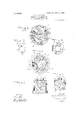
- igure 1 1s a longitudinal sectional eleval tion of the improvement as a plied to the front axle of a power-driven ve icle;
- Fig. 2 is a lan view of the joints-between the main axIfe and its stub and drive shaft and its stub axle;
- Fig. 3 isan enlarged transverse section of the improvement on the" line 3-3y of Fig. l ,z- Fig. 41s asimilar view of the saniejon the line 4-4 of Fig. 1;
- Fi 5 is a sectional' plan View of the same ont e line 5-5 of/Figl; Ilig. ⁇ 6 isratlike viewof the same showing'the partsina different position;
- Fig. 7 isaface view of the ring on the end, of the stub axle,
- Fig.y 8 is an end elevation' of. thestub Y axle.
- the main axle A is providedfwith bearings for the drive 'shaft B connected by'sprocket wheels and chain or other devices with the motor, so as to allow of rotating the shaftB,
- Themainvaxle A is provided with a stub axle C, on which is j ournaled the vehicle wheelD, the said stub axle C being connected at lits pivot with the usual steering gear E, toallow 'of steering the stub axle C in the desired direction for cproperly steering the vehicle.
- Each en of the drive shaft B is connected by a universal joint F with a stub shaft G Specification of Letters Patent. Application led August 51, '197077. Serial No. 390,951.
- each pawl I having its pivot I 'ournaled in suity able bearings arranged in t e sleeve H.
- a shifting arm I adapted yto be engaged by a spring J attached to a shifting ring J, mounted to turn loosely on the inner end of thevsleeve H.
- the shifting ring J is pro# vided with a stop pin J 2 extending into a recess H2 formed on the sleeve H (see Fig. 4), to limit the turning motion of the shiftin ring J.
- the shiftin ring J is also provide with a pin J3 exten ing into an elongated. aperture K formed in the shifting lever K, pivoted at KZ on 'the sleeve H, as plainl indicated in Fi' s.5 and l6.
- the free en( K3 of the shifting ever K is adapted to be engaged by one or more projections L, formed on the ring L provided with recesses L2 (see Fig.
- Sprin s and attached to the sleeve H are a a ted 'to press o posite sides le; of the -ever to prevent by the projection L.
- both wheels f, on the front or rear axle are ositively driven w ini'either forward or bac ⁇ wa-rd direction from the motor, but each wheel on the front orrear axle is free to turn independent oic the other, 'thus allowing one wheel to turn faster than the other when steering the vehicle around a corner, so that tliei'sliaft B and wheel tiresare relieved oi' all undue strain.
- the vehiclewheel provided with a ub having internally arranged teeth
- a power transmission for vehicles com vprising the vehicle wheel provided with a hub having internally 'arranged teeth, an axle on which vtl ie wheel is wartorialed, a driving shaft in the axle and having its free end polygonal Yin cross section, a sleeve 'litting on the end of' the driving shaft, pawls jonrnaled in the sleeve and engaging the teeth of the hub, a'
- shifting arm in connection witlieaeh pawl, a shifting ring encircling the sleeve and provided with springs for engaging the shifting arm at different points whereby to reverse the engagement of the pawl, and means in connection with the axle for operating the shifting ring to reverse the pawls when the motion of'the ⁇ drivinglslialt reversed.
- a power transmission for vehicles comprising a vehicle wheel, -a drive shaft, a iixed axle for the drive shalt and wheel to turn on independent one of the other, a ratchetmechn anism connectingtlie said drive shaft with the said vehicle wheel and havinga double Ipawl .for engagement with teeth on lthe hub of the vehicle wheel a tripping aiin on the pivot of the said pawl, a ring mounted to turn and 3 lia-ving means for engaging the said tripping arm to swing the.
Description
TENTED JULY 14, 1908.
2 SEEBTS-SHBET 1,
WLLAMS.
TRANSMISSON.
POWER APPLIGMION FILED AUG. 31, 1907.
JOHN LEONIDAS` WILLIAMS, OF ELLZEY, FLORIDA.
POWER. TRANSMISSION.
wheels of the front or rear axle to turn independent one of the other when' steering the machine around "corners, thusrelieving the y drlvmg shaft of all undue strain.
l is represented in the accompanyingv The invention consists of novel features which will be more fully described hereinafter and then ointed out in the claims.
A practica embodiment of the invention drawings forming a part of this specification, in which similar characters of reference indicate corres onding parts in all the views.
and Fig.y 8 is an end elevation' of. thestub Y axle.
l .f The main axle A is providedfwith bearings for the drive 'shaft B connected by'sprocket wheels and chain or other devices with the motor, so as to allow of rotating the shaftB,
in either a forward or backward direction',
Themainvaxle A is provided with a stub axle C, on which is j ournaled the vehicle wheelD, the said stub axle C being connected at lits pivot with the usual steering gear E, toallow 'of steering the stub axle C in the desired direction for cproperly steering the vehicle.
Each en of the drive shaft B is connected by a universal joint F with a stub shaft G Specification of Letters Patent. Application led August 51, '197077. Serial No. 390,951.
of the free end the latter from being swung outof position Patented July 14, 190s.
sleeve H dittin in the outer end of the hub D of the vehic e Wheel D. On the inside of the hub D are formed teeth D2 adapted to be engaged by one or more double awls I extendin in the recesses H forme in the periphera face of the sleeve H (see Fig..3) each pawl I having its pivot I 'ournaled in suity able bearings arranged in t e sleeve H. On the pivot I of each pawl I is secured a shifting arm I, adapted yto be engaged by a spring J attached to a shifting ring J, mounted to turn loosely on the inner end of thevsleeve H. The shifting ring J is pro# vided with a stop pin J 2 extending into a recess H2 formed on the sleeve H (see Fig. 4), to limit the turning motion of the shiftin ring J. The shiftin ring J is also provide with a pin J3 exten ing into an elongated. aperture K formed in the shifting lever K, pivoted at KZ on 'the sleeve H, as plainl indicated in Fi' s.5 and l6. The free en( K3 of the shifting ever K is adapted to be engaged by one or more projections L, formed on the ring L provided with recesses L2 (see Fig. 7), into which extend lugs C formed on the outer end of the stub axle C (see Figs. 1 and 8), to hold the 'rin L yin lace on the stub axle C. Sprin s and attached to the sleeve H are a a ted 'to press o posite sides le; of the -ever to prevent by the projection L.
The operation is as follows: When the several parts are in the osition illustrated in Figs. 1, 3, 4 and 5, an the shaft B is rotated in a forward direction, then the stub shaft G and the sleeve H turn with the shaft I corresponding pawl I, whereby the pref' viously engaged end of-pawl I is moved out .of engagement with the teeth D2, While the other end ofthe awl I moves into engagement with the sald teeth, and consequently the hub D and '-\the vehicle wheel D are turned in a reverse direction; It is understood that as the projections L are stationary on the stationaryistub axle C it is evident that whenever the sleeve H is turned in K yields to allow the 'free end KJ of the lever K to pass the lug L when the shaft B is turned in either a forward or a backward direction. i l
By the arrangement described both wheels f, on the front or rear axle are ositively driven w ini'either forward or bac {wa-rd direction from the motor, but each wheel on the front orrear axle is free to turn independent oic the other, 'thus allowing one wheel to turn faster than the other when steering the vehicle around a corner, so that tliei'sliaft B and wheel tiresare relieved oi' all undue strain.
It will'also be noticed that the driving shaft vB is relieved of the weight of the machine and-hence the shalt' rB can be readily driven with comparatively little power.
,i the hejoints, stu vomitted.n
Altlioughthe Apower transmission is shown for use on the front axle, it is evident that it can bev readily applied on arear-axle in which shaft vand stub axle are Having .thus described my -inventiom I vclaim as new and desire to secure by Letters 1.` A power *transmission for Vehicles, comv rising the vehicle wheel provided With a hub raving internally arrangedteeth, an axle, a :stub axley pivoted to the endof the axle and on which the Ywheel is journaled, a` driving -shaft inthe axle, a stub shaft connected by universal joint withthe end oflthedriving shaft,y the free end of said stub shaft being polygonal in cross section, a sleeve fitting on i the end of the stub shalt, pawls provided with pivot pins ournaled in the sleeve, a shifting arm in connection with the pivot of each pawl, a shifting ring encircling the sleeve, and provided with springs lor engaging the shiftling arm at diil'ereiit points whereby to reverse the vengagement of the pawlrwitli the teethof the hub, a stoppin for limiting the inotiol'rol the ring, a shifting lever providcil:
witha slot, a pin 'on the ring for .engaging the v slot, .a ring provided with projections con 'nected with the .stub axle, and springs for' Ilimiting the motion of thesaid shifting lever.
the vehiclewheel provided with a ub having internally arranged teeth, an
axle on which thewheel is journaled, a driv' in shaft in the axle and having its free' 'end po ygonal in cross section, a'sleeve fitting on -tlieend et' the-driving shaft, paw'ls provided with pivot pins journaled in the-sleeve, a shifting armin connection with the pivot of 2. A power transmission for vehiclesfcom-v each pawl, a shifting ring encircling the sleeve,
in cross section, a sleeve fitting on the end et the driving shaft, `pawls provided with pivot pins jouinaled in the sleeve, a shifting arm in connection with the pivot of each pawl, a shifting ring encircling the sleeve, and provided with springs for engaging the shifting arm at different points whereby toreverse the engagement of the pawl with the teethof the hub, and means connected with the axle lfor shifting the ring when the movement of the driving shaft is reversed. 4
'4. A power transmission for vehicles, com vprising the vehicle wheel provided with a hub having internally 'arranged teeth, an axle on which vtl ie wheel is joiiriialed, a driving shaft in the axle and having its free end polygonal Yin cross section, a sleeve 'litting on the end of' the driving shaft, pawls jonrnaled in the sleeve and engaging the teeth of the hub, a'
shifting arm in connection witlieaeh pawl, a shifting ring encircling the sleeve and provided with springs for engaging the shifting arm at different points whereby to reverse the engagement of the pawl, and means in connection with the axle for operating the shifting ring to reverse the pawls when the motion of'the` drivinglslialt reversed.
i 5. A power transmission for vehicles, comprising a vehicle wheel, -a drive shaft, a iixed axle for the drive shalt and wheel to turn on independent one of the other, a ratchetmechn anism connectingtlie said drive shaft with the said vehicle wheel and havinga double Ipawl .for engagement with teeth on lthe hub of the vehicle wheel a tripping aiin on the pivot of the said pawl, a ring mounted to turn and 3 lia-ving means for engaging the said tripping arm to swing the. pawl in either direction, a spring-pressed shitting ariii engaging the said ring for shifting the latter, and a projec- ".`tioii on the said aide-for engagiiiglthe said ,"sliifting arm.
' --iIntestimony whereof I have signed my nam'eft'o'fthis specification in the presence of two V scribing witnesses."
f Jol-IN LE'IDAS WILLIAMS. Witnesses:
f BERRY' CANNON,
CHAR-Las L; TINDAL;
Priority Applications (1)
| Application Number | Priority Date | Filing Date | Title |
|---|---|---|---|
| US39095107A US893409A (en) | 1907-08-31 | 1907-08-31 | Power transmission. |
Applications Claiming Priority (1)
| Application Number | Priority Date | Filing Date | Title |
|---|---|---|---|
| US39095107A US893409A (en) | 1907-08-31 | 1907-08-31 | Power transmission. |
Publications (1)
| Publication Number | Publication Date |
|---|---|
| US893409A true US893409A (en) | 1908-07-14 |
Family
ID=2961838
Family Applications (1)
| Application Number | Title | Priority Date | Filing Date |
|---|---|---|---|
| US39095107A Expired - Lifetime US893409A (en) | 1907-08-31 | 1907-08-31 | Power transmission. |
Country Status (1)
| Country | Link |
|---|---|
| US (1) | US893409A (en) |
-
1907
- 1907-08-31 US US39095107A patent/US893409A/en not_active Expired - Lifetime
Similar Documents
| Publication | Publication Date | Title |
|---|---|---|
| US2531819A (en) | Reversible ratchet drive mechanism for power vehicles | |
| US893409A (en) | Power transmission. | |
| US994359A (en) | Driving and brake mechanism for velocipedes. | |
| US1262562A (en) | Four-wheel drive mechanism. | |
| US2006261A (en) | Ratchet device for preventing the rearward motion of power driven vehicles | |
| US728420A (en) | Differential gear for motor-vehicles. | |
| US675360A (en) | Vehicle. | |
| US1294317A (en) | Travel-controlling mechanism for tractors. | |
| US1017407A (en) | Transmission mechanism for automobiles. | |
| US2343469A (en) | Automotive drive | |
| US1420706A (en) | Differential mechanism | |
| US1294985A (en) | Rear-axle drive mechanism for automobiles. | |
| US1590129A (en) | Differential | |
| US943744A (en) | Automobile driving mechanism. | |
| US609955A (en) | brightmore | |
| US809338A (en) | Power-transmitting mechanism for motor-vehicles. | |
| US1107710A (en) | Clutch. | |
| US1297503A (en) | Spring-motor automobile. | |
| US1037466A (en) | Starter for explosion-engines and self-propelled vehicles. | |
| US788014A (en) | Traction-wheel. | |
| US225050A (en) | Traction-engine | |
| US855774A (en) | Power-transmitting mechanism. | |
| US520688A (en) | George w | |
| US645926A (en) | Brake for vehicles. | |
| US1099901A (en) | Coaster-brake. |