US8932092B1 - Waterjet propulsor with shaft fairing device - Google Patents
Waterjet propulsor with shaft fairing device Download PDFInfo
- Publication number
- US8932092B1 US8932092B1 US13/920,214 US201313920214A US8932092B1 US 8932092 B1 US8932092 B1 US 8932092B1 US 201313920214 A US201313920214 A US 201313920214A US 8932092 B1 US8932092 B1 US 8932092B1
- Authority
- US
- United States
- Prior art keywords
- impeller
- elongated sleeve
- flow
- frame
- shaft
- Prior art date
- Legal status (The legal status is an assumption and is not a legal conclusion. Google has not performed a legal analysis and makes no representation as to the accuracy of the status listed.)
- Active
Links
Images


Classifications
-
- B—PERFORMING OPERATIONS; TRANSPORTING
- B63—SHIPS OR OTHER WATERBORNE VESSELS; RELATED EQUIPMENT
- B63H—MARINE PROPULSION OR STEERING
- B63H11/00—Marine propulsion by water jets
- B63H11/02—Marine propulsion by water jets the propulsive medium being ambient water
- B63H11/04—Marine propulsion by water jets the propulsive medium being ambient water by means of pumps
- B63H11/08—Marine propulsion by water jets the propulsive medium being ambient water by means of pumps of rotary type
- B63H2011/081—Marine propulsion by water jets the propulsive medium being ambient water by means of pumps of rotary type with axial flow, i.e. the axis of rotation being parallel to the flow direction
Definitions
- the following description relates generally to a waterjet propulsor, more particularly, an elongated sleeve or housing covering the impeller shaft, the elongated sleeve or housing being free-floating or fixed, and having an airfoil section for optimizing the flow over the shaft, thereby increasing propulsive efficiency.
- FIG. 8A is a prior art illustration of a typical waterjet propulsor 10 .
- the propulsor 10 includes an impeller shaft 20 with impeller blades 30 and impeller hub 80 .
- the shaft 20 has a substantially circular cross section, and is mounted at the forward end via a forward bearing arrangement 40 to the propulsor frame structure 50 .
- the shaft is mounted at the aft end via an aft bearing arrangement 41 to the stator/nozzle assembly 70 .
- FIG. 8A also shows the intake 60 , through which the propulsor inlet flow is developed.
- the shaft 20 is situated entirely within the flow field, indicated by arrows F, created upstream of the impeller.
- the shaft 20 presents an obstruction to flow creating turbulence and a large wake region within the housing of the propulsor, downstream of the shaft. This introduces turbulence and extreme variations in the velocities and pressures of the flow field entering the plane of the impeller blades 30 .
- the turbulence introduced is due to the location of the shaft, the shape of the shaft, and the rotational movement of the shaft.
- the impeller shaft 20 is positioned directly in the path of the intake fluids, thereby obstructing the flow into the impeller blades 30 .
- the cross sectional shape of the impeller shaft 20 Being a right circular cylinder, the cross sectional shape of the impeller shaft 20 possesses one of the highest drag coefficients for a non-blunt object.
- FIG. 8B shows the character of the drag coefficient as a function of Reynolds number for fluid flow over objects of different cross-sectional shapes, including that of a circle and an ellipse. It should be noted that in actuality, because of the angle ⁇ (shown in FIG. 8A ) at which the flow approaches the shaft 20 , the shaft cross section over which flow occurs may be more akin to an ellipse, which is more efficient than a circle, but less efficient than an airfoil.
- the surface of shaft 20 is not stationary, but rotating. Consequently, additional detrimental boundary layer effects associated with the tangential velocity of the shaft surface are introduced due to the shaft rotation (Magnus effect).
- the prior art does not provide a propulsor structure that minimizes the deleterious effects of the shaft to optimize the operation of the propulsor.
- the invention is a waterjet propulsor having a frame with a forward end, an aft end, an upper end, and a lower end.
- the waterjet propulsor also has a nozzle assembly located at the aft end of the frame.
- the waterjet propulsor also includes an impeller assembly.
- the impeller assembly has a forward impeller bearing arrangement at the forward end of the frame, an aft impeller bearing arrangement at the aft end of the frame, and an impeller shaft extending from the forward end of the frame to the aft end of the frame in a longitudinal direction X and mounted within each of the forward impeller bearing arrangement and the aft impeller bearing arrangement.
- the impeller assembly also includes an impeller blade assembly having a central hub and a plurality of blades attached to the central hub, wherein the central hub is supported on the impeller shaft.
- the waterjet propulsor has a water intake extending from the lower end of the frame towards the impeller, the water intake having intake walls forming a conduit, wherein the conduit is angled to create an intake flow F I having flow vectors in perpendicular X, Y, and Z axes, and wherein intake flow F I-xy in the X-Y plane impinges on the impeller shaft at an angle ⁇ with respect to the longitudinal direction X of the shaft.
- the invention also includes an elongated structure positioned over the impeller shaft, wherein the elongated structure has an airfoil cross section in the Y-Z plane.
- the elongated structure also has an offset streamlined airfoil cross section aligned with the intake flow angle ⁇ , so that the intake flow F I-xy flows over the elongated structure in a path defined by the offset streamlined airfoil cross section, thereby minimizing the deleterious flow effects caused by the shaft, and increasing the efficiency of the propulsor.
- the invention is a method of optimizing the flow within a waterjet propulsor.
- the method includes the step of providing a waterjet propulsor having a frame having a forward end, an aft end, an upper end, and a lower end.
- the waterjet propulsor is also provided with a nozzle assembly located at the aft end of the frame, and an impeller assembly.
- the impeller assembly includes a forward impeller bearing arrangement at the forward end of the frame, an aft impeller bearing arrangement at the aft end of the frame, an impeller shaft extending from the forward end of the frame to the aft end of the frame in a longitudinal direction X and mounted within each of the forward impeller bearing arrangement and the aft impeller bearing arrangement.
- the impeller assembly includes an impeller blade assembly having a central hub and a plurality of blades attached to the central hub, wherein the central hub is supported on the impeller shaft.
- the propulsor also includes a water intake extending from the lower end of the frame towards the impeller, the water intake having intake walls forming a conduit, wherein the conduit is angled to create an intake flow F I having flow vectors in perpendicular X, Y, and Z axes.
- the method further includes the step of providing an elongated structure positioned over the impeller shaft, wherein the elongated structure has an airfoil cross section in the Y-Z plane.
- the method also includes the directing of the intake flow F I having intake flow vector F I-xy in the X-Y plane into the waterjet propulsor, the intake flow F I-xy impinging on the impeller shaft at an angle ⁇ with respect to the longitudinal direction X of the shaft.
- the elongated structure further comprises an offset streamlined airfoil cross section aligned with the intake flow angle ⁇ , so that the intake flow F I-xy flows over the elongated structure in a path defined by offset streamlined airfoil cross section, thereby minimizing the deleterious flow effects caused by the shaft, and increasing the efficiency of the propulsor.
- the invention is an elongated sleeve for optimizing flow in a waterjet propulsor having a frame with a forward end, an aft end, an upper end, and a lower end, a nozzle assembly located at the aft end of the frame, and an impeller assembly.
- the impeller assembly has a forward impeller bearing arrangement at the forward end of the frame, an aft impeller bearing arrangement at the aft end of the frame, an impeller shaft extending from the forward end of the frame to the aft end of the frame in a longitudinal direction X and mounted within each of the forward impeller bearing arrangement and the aft impeller bearing arrangement.
- the impeller assembly also includes an impeller blade assembly having a central hub and a plurality of blades attached to the central hub, wherein the central hub is supported on the impeller shaft.
- the waterjet propulsor also has a water intake extending from the lower end of the frame towards the impeller, the water intake having intake walls forming a conduit, wherein the conduit is angled to create an intake flow F I having flow vectors in perpendicular X, Y, and Z axes, and wherein intake flow F I-xy in the X-Y plane impinges on the impeller shaft at an angle ⁇ with respect to the longitudinal direction X of the shaft, the elongated sleeve positioned over the impeller shaft and having an airfoil cross section in the Y-Z plane, the elongated sleeve further having an NACA 0030 offset streamlined airfoil cross section aligned with the intake flow angle ⁇ , so that the intake flow F I-xy flows over elongated slee
- FIG. 1 is an exemplary illustration of an optimized waterjet propulsor, according to an embodiment of the invention.
- FIGS. 2A-2C are exemplary illustrations of an elongated sleeve and an impeller assembly, according to an embodiment of the invention.
- FIG. 2D is an exemplary sectional illustration of an elongated sleeve positioned over an impeller shaft, according to an embodiment of the invention
- FIG. 3A is an exemplary illustration of an elongated sleeve, showing the angular relation between the elongated sleeve and the intake flow path, according to an embodiment of the invention.
- FIG. 3B is an exemplary sectional taken through line B-B′ of FIG. 3A , according to an embodiment of the invention.
- FIG. 3C is an exemplary sectional taken through line C-C′ of FIG. 3A , according to an embodiment of the invention.
- FIG. 3D is an exemplary explanatory illustration of the intake flow approaching the elongated sleeve, according to an embodiment of the invention.
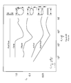
- FIGS. 4A-4B are explanatory illustrations demonstrating the angular alignment of the elongated sleeve, according to an embodiment of the invention.
- FIG. 5 is an exemplary sectional illustration of the flow over the elongated sleeve, according to an embodiment of the invention.
- FIG. 6 is an exemplary illustration of an optimized waterjet propulsor 600 , according to an embodiment of the invention.
- FIG. 7A is an exemplary illustration of an elongated structure, according to an embodiment of the invention.
- FIG. 7B is an exemplary sectional illustration through B-B′ of FIG. 7A , according to an embodiment of the invention.
- FIG. 7C is an exemplary sectional illustration through C-C′ of FIG. 7A , according to an embodiment of the invention.
- FIG. 8A is a prior art illustration of a waterjet propulsor.
- FIG. 8B shows the typical fluid flow over streamlined objects of different cross sectional shapes, including that of a circle and an ellipse.
- FIG. 1 is an exemplary illustration of an optimized waterjet propulsor 100 , according to an embodiment of the invention.
- the propulsor 100 includes having a frame structure 50 and stator/nozzle assembly 70 .
- the frame structure 50 has an aft end 120 , a forward end 122 , an upper end 124 , and a lower end 126 .
- the waterjet propulsor 100 includes an impeller assembly, having an impeller shaft 20 , with a central impeller hub 80 and impeller blades 30 mounted on the hub 80 .
- the impeller shaft 20 which has a circular cross section, extends longitudinally in an X-direction from the forward end 122 to the aft end 120 of the frame 50 .
- the shaft 20 is supported within the chassis via a forward impeller bearing arrangement 40 at the forward end 122 .
- the shaft 20 is also supported within the stator/nozzle assembly 70 at the aft end 120 by an aft impeller bearing assembly 41 .
- the propulsor 100 includes an intake 170 located at the lower end 126 of the frame.
- FIG. 1 shows intake walls 172 forming an angled intake conduit 175 .
- FIG. 1 also shows a stator/nozzle assembly 70 located at the aft end 120 of the propulsor 100 .
- Arrow F 1 shows the intake flow of water entering the waterjet propulsor, as water enters through the intake 170 .
- the intake flow F I includes flow vectors in the three perpendicular directions X, Y, and Z.
- the intake flow F I-xy shown represents the flow vectors in the X-Y plane.
- the flow vectors in a Z direction are not illustrated in FIG. 1 .
- the intake flow F I-xy approaches the elongated sleeve 300 (which covers the impeller shaft 20 ) at an angle in the X-Y plane, as opposed to directly in the Y-direction.
- Arrows F O represent the outflow of water that passes through the stator/nozzle assembly 70 .
- the outflow F O shown is the output flow and also includes flow vectors in the three perpendicular X, Y, and Z axes.
- the F O-xy arrow shows the outflow in the X-Y plane. As stated above, the flow vectors in a Z direction are not illustrated in FIG. 1 .
- FIG. 1 shows an elongated sleeve 300 , positioned over the shaft 20 .
- the sleeve 300 is mounted to rotate freely with respect to the shaft 20 , and as shown in FIG. 3B , the elongated sleeve 300 has a geometry having an airfoil cross section in the Y-Z plane.
- the elongated sleeve 300 also includes an offset streamlined airfoil cross section aligned with the intake flow F I-xy path, so that the intake flow F I-xy flows over the elongated structure in a path defined by the offset streamlined airfoil cross section, thereby minimizing the deleterious flow effects caused by the shaft, and increasing the efficiency of the propulsor. Also outlined below is the rotational adjustability of the elongated sleeve 300 in the Y-Z plane, thereby aligning the elongated sleeve with intake flow.
- FIGS. 2A-2C are exemplary illustrations of an elongated sleeve 300 and an impeller assembly, according to an embodiment of the invention.
- FIGS. 2A-2C all show the impeller shaft 20 mounted on forward and aft impeller bearing arrangements ( 40 , 41 ).
- FIGS. 2A-2C also show the impeller blade assembly having a central hub 80 and a plurality of blades 30 attached to the central hub 80 .
- longitudinal axis 315 in the X-direction which extends through the impeller shaft 20 .
- the impeller shaft 20 is substantially parallel to the longitudinal axis 315 , and by means of the bearings ( 40 , 41 ), rotates about the axis 315 .
- FIG. 2A is an exemplary perspective sectional, showing the elongated sleeve positioned over the shaft 20 .
- FIG. 2B is an exemplary side view, showing the elongated sleeve 300 positioned over the shaft 20 .
- FIGS. 2A and 2B are different views of the same arrangement.
- FIG. 2C shows the shaft 20 with the sleeve 300 removed.
- FIG. 2D is an exemplary sectional illustration, showing a section through D-D′ of in the illustration of FIG. 2A .
- turbulence may be introduced into the propulsor 100 because the shaft 20 extends into the intake flow path F I .
- the circular sectional shape of the shaft 20 and the rotational movement of the shaft contribute to inefficiencies.
- the elongated sleeve 300 reduces deleterious flow effects by streamlining the flow F I over the impeller shaft 20 .
- FIG. 2D shows a running clearance 301 between the sleeve 300 and the shaft 20 on account of the difference between the shaft diameter D SH and the sleeve diameter D SL .
- the elongated sleeve 300 has an inner diameter D SL that is slightly larger than the outer diameter D SH of the impeller shaft.
- the running clearance 301 (shown exaggerated for clarity) facilitates a free-floating arrangement between the elongated sleeve 300 and the impeller shaft 20 , allowing for the self-alignment of the sleeve 300 with the intake flow F I .
- this free-floating adjustability is in the Y-Z plane.
- the sleeve 300 may be manufactured via CNC milling of a monolithic block of homogeneous and easily machinable material.
- the sleeve material may be an ultra-high molecular weight polyethylene (UHMWPE), or the like. The inherent properties of this material meet or exceed the above-outlined characteristics.
- water fills the running clearance 301 and acts as a lubricant, further facilitating the free-floating of the elongated sleeve 300 on the shaft 20 .
- the shaft 20 is also freely rotatable within the sleeve 300 . Axial movement of the elongated sleeve 300 along the shaft 20 is prevented by abutment portions 51 (shown in FIG. 1 ) of the frame structure 50 at the forward end of the sleeve 300 , and by the impeller hub 80 at the aft end of the sleeve 300 .
- abutment portions 51 shown in FIG. 1
- FIG. 3A is an exemplary illustration of an elongated sleeve 300 , showing the angular relation between the elongated sleeve 300 and the intake flow path F I-xy , according to an embodiment of the invention.
- FIG. 3A represents the flow vectors in the X-Y plane.
- FIG. 3A also shows a longitudinal axis 315 extending longitudinally (in the X-direction) through the center of an opening 305 (shown in FIG. 3B ).
- FIG. 3B shows a sectional view through B-B′ of the elongated sleeve 300 , taken normal to axis 315 , representing a view in the Y-Z plane.
- the illustrated section 300 B shows the elongated sleeve 300 having an airfoil profile with a circular opening 305 for receiving the shaft 20 therethrough.
- FIG. 3C shows a sectional view through C-C′ of sleeve 300 , taken at the angle ⁇ at which the intake flow F I-xy approaches the sleeve 300 .
- the illustrated section 300 C is an offset streamlined section defined by the path taken by the intake flow F I-xy as it travels over the elongated sleeve 300 .
- the section 300 C is an offset airfoil section that coincides with the intake flow direction.
- the section 300 c may have a NACA 0030 profile.
- the intake flow F I-xy and angle ⁇ is representative of a plurality of flow components (f i-xy1 , f i-xy2 , f i-xy3 . . . f i-xyN ) and corresponding angles ( ⁇ 1 , ⁇ 2 , ⁇ 3 . . . ⁇ N ), where ‘N’ is an integer.
- FIG. 3D shows these flow components and angles, and is an explanatory illustration of the intake flow FI -xy approaching the elongated sleeve 300 , according to an embodiment of the invention.
- each flow component (f i-xy1 , f i-xy2 , f i-xy3 . . . f i-xyN ) approaches at respective ( ⁇ 1 , ⁇ 1 , ⁇ 1 . . . ⁇ N ) angles.
- the ( ⁇ 1 , ⁇ 2 , ⁇ 3 . . . ⁇ N ) angles may vary along the length of the elongated sleeve 300 , however the path of each component is generally as illustrated in FIG. 3C .
- each flow component follows an offset streamlined airfoil path as shown in FIG. 3C , as opposed to the more squat and less streamlined cross section shown in FIG. 3B .
- This offset streamlined airfoil path minimizes the deleterious flow effects caused by the shaft, and improves the efficiency of the propulsor.
- the intake flow F i-xy shown represents the flow vectors in the X-Y plane.
- the elongated sleeve 300 has a short and squat airfoil section in the Y-Z plane, but because of the intake flow angle ⁇ , the intake flow F I-xy follows the offset streamlined airfoil path 300 C as shown in FIG. 3C .
- This offset streamlined airfoil path minimizes the deleterious flow effects caused by the shaft, and improves the efficiency of the propulsor.
- additional alignment is required to accommodate for Z-direction flow vectors. This additional alignment is necessary to optimize the flow over the elongated sleeve 300 , and in particular, to optimize the flow in the offset streamlined airfoil path.
- FIGS. 4A-4B are explanatory illustrations demonstrating the angular alignment of the elongated sleeve 300 , according to an embodiment of the invention. More specifically, FIGS. 4A-4B show the elongated sleeve 300 over the shaft 20 . FIGS. 4A-4B also show the running clearance 301 between the shaft 20 and the sleeve 300 , which allows for rotational adjustments.
- the FIG. 4A-4B illustrations are in the Y-Z plane and thus, the views show the section 300 B of the elongated sleeve 300 , and the rotational adjustment necessary to correct for variations of the intake flow F I-yz in the Y-Z plane. Rotational adjustments are performed by the self-alignment of the elongated sleeve 300 due to the friction drag forces created by the intake flow F I .
- FIG. 4A shows the sleeve 300 in an initial position 401 with respect to the Y and Z axes, as might be the case when the waterjet is not operational and there is no intake flow F I present.
- the resulting incident intake flow F I-yz impinges on the elongated sleeve 300 as shown in FIG. 4B .
- the elongated sleeve is not aligned with the intake flow F I-yz , and thus, the flow over the airfoil section is not optimized to reduce turbulence.
- the incident intake flow F I-yz approaches the sleeve 300 at an angle of attack corresponding to the angle ⁇ between the F I-yz direction and a chord line 400 .
- the chord line 400 extends from the apex of the section, through the midpoint of the circular opening 305 to the base of the section.
- the angle ⁇ between the incident intake flow F I-yz and the chord line 400 should be zero.
- the sleeve 300 must rotate ⁇ degrees to the adjusted position 402 , shown in dotted lines in FIG. 4B .
- FIG. 4B shows the angular adjustment ⁇ from position 401 to position 402 as a counter-clockwise adjustment, adjustments may be made in any direction to adjust for misalignment of elongated sleeve 300 with the intake flow F I-yz .
- ⁇ may be zero.
- the elongated sleeve 300 is in a free-floating arrangement with respect to the shaft 20 .
- the elongated sleeve 300 self-aligns to make the angular adjustment ⁇ from position 401 to position 402 .
- the operating fluid in the running clearance 301 acts as a lubricant during the aligning movements of the free-floating elongated sleeve 300 .
- the self-aligning function is achieved due to the friction drag forces created by the intake flow F I . Consequently, during operation, the free-floating arrangement allows for continuous adjustments due to any variation in the intake flow F I .
- FIG. 5 is an exemplary sectional illustration of the flow over the elongated sleeve, according to an embodiment of the invention. More specifically, FIG. 5 shows the flow of water over the airfoil section 300 C at offset angle ⁇ , and at adjusted angle ⁇ . Because of the geometry of the elongated sleeve 300 , and also because of the ability to adjust rotationally as shown in FIG. 4 , the flow over the airfoil section is as illustrated in FIG. 5 .
- the resulting streamlined flow over the airfoil section results in the reduction of drag.
- the reduction in drag has the benefit of reducing upstream flow influence.
- An additional benefit is the increase in mass flow through the nozzle 70 , increasing the efficiency of the propulsor. This results in increased thrust, increased craft speed, and an increased cavitation inception margin.
- FIG. 6 is an exemplary illustration of an optimized waterjet propulsor 600 , according to an embodiment of the invention.
- the arrangement of the waterjet propulsor 600 is similar to that of illustration in FIG. 1 . Consequently, like elements in FIG. 6 are numbered to correspond to like elements shown in FIG. 1 .
- element 20 is also a propulsor shaft
- element 40 is also a forward bearing arrangement
- element 41 is also an aft bearing arrangement, the bearings ( 40 , 41 ) for supporting and rotating the shaft 20 .
- the waterjet propulsor 600 includes a rigid elongated structure 650 attached to the frame 50 and extending from the forward end of the frame towards impeller blade assembly.
- the elongated structure 650 may be attached to the frame 50 or may be integrally formed with the frame 50 . Because the elongated structure 650 is rigidly attached to the frame 50 , the elongated structure 650 is not rotatable.
- FIG. 7A is an exemplary illustration of an elongated structure 650 , showing the angular relation between the elongated structure 650 and the intake flow path F i-xy , according to an embodiment of the invention.
- the illustration of FIG. 7A is similar to that of FIG. 3A , and thus the FIG. 7A features for optimizing the flow are similar to those outlined previously with respect to FIG. 3A .
- the intake flow F i-xy shown in FIG. 7A represents the flow vectors in the X-Y plane.
- FIG. 7B shows a sectional view through B-B′ of the rigid elongated structure 650 , taken normal to axis 615 (shown in FIG.
- the illustrated section 650 B shows the elongated structure 650 having an airfoil profile with a circular opening 605 for receiving the shaft 20 therethrough.
- FIG. 7C shows a sectional view through C-C′ of elongated structure 650 , taken at the angle ⁇ at which the intake flow F-x, approaches the elongated structure 650 .
- the illustrated section 650 C is an offset streamlined section defined by the path taken by the intake flow F i-xy as it travels over the elongated structure 650 .
- the section 650 C is an offset airfoil section that coincides with the intake flow direction.
- the offset streamlined section may have a NACA 0030 profile.
- the intake flow F i-xy and angle ⁇ is representative of a plurality of flow components (f i-xy1 , f i-xy2 , f i-xy3 . . . f i-xyN ) and corresponding angles ( ⁇ 1 , ⁇ 2 , ⁇ 3 . . . ⁇ N ), where ‘N’ is an integer, as outlined above with respect to FIG. 3D .
- N is an integer
Landscapes
- Chemical & Material Sciences (AREA)
- Engineering & Computer Science (AREA)
- Combustion & Propulsion (AREA)
- Mechanical Engineering (AREA)
- Ocean & Marine Engineering (AREA)
- Structures Of Non-Positive Displacement Pumps (AREA)
Abstract
Description
Claims (16)
Priority Applications (1)
| Application Number | Priority Date | Filing Date | Title |
|---|---|---|---|
| US13/920,214 US8932092B1 (en) | 2013-06-18 | 2013-06-18 | Waterjet propulsor with shaft fairing device |
Applications Claiming Priority (1)
| Application Number | Priority Date | Filing Date | Title |
|---|---|---|---|
| US13/920,214 US8932092B1 (en) | 2013-06-18 | 2013-06-18 | Waterjet propulsor with shaft fairing device |
Publications (1)
| Publication Number | Publication Date |
|---|---|
| US8932092B1 true US8932092B1 (en) | 2015-01-13 |
Family
ID=52247700
Family Applications (1)
| Application Number | Title | Priority Date | Filing Date |
|---|---|---|---|
| US13/920,214 Active US8932092B1 (en) | 2013-06-18 | 2013-06-18 | Waterjet propulsor with shaft fairing device |
Country Status (1)
| Country | Link |
|---|---|
| US (1) | US8932092B1 (en) |
Cited By (3)
| Publication number | Priority date | Publication date | Assignee | Title |
|---|---|---|---|---|
| US10118696B1 (en) | 2016-03-31 | 2018-11-06 | Steven M. Hoffberg | Steerable rotating projectile |
| CN115649432A (en) * | 2022-10-27 | 2023-01-31 | 南京航空航天大学 | Hydrodynamic helicopter for advancing close to water surface |
| US11712637B1 (en) | 2018-03-23 | 2023-08-01 | Steven M. Hoffberg | Steerable disk or ball |
Citations (14)
| Publication number | Priority date | Publication date | Assignee | Title |
|---|---|---|---|---|
| US1104254A (en) * | 1912-06-28 | 1914-07-21 | Gustav R Eddelbuttel-Reimers | Strut-cover of stream-line surface. |
| US4470364A (en) * | 1981-11-04 | 1984-09-11 | Kawasaki Jukogyo Kabushiki Kaisha | Side thruster of a boat |
| US4854903A (en) * | 1987-12-17 | 1989-08-08 | Copeland-Sirois Enterprises, Inc. | Parallel thrust propulsion system |
| US5232386A (en) * | 1992-12-10 | 1993-08-03 | Gifford William J | Counter rotating strut drive |
| US5722340A (en) * | 1996-12-11 | 1998-03-03 | Mobil Oil Corporation | Fairing for marine risers |
| US5839927A (en) | 1996-10-31 | 1998-11-24 | United Defense, Lp | Water jet system |
| US6244204B1 (en) | 1998-11-03 | 2001-06-12 | Odim Holding Asa | Fairing for a towed cable |
| US20030027467A1 (en) * | 2001-08-03 | 2003-02-06 | Suits Gary Todd | Shaft guard |
| US6913496B2 (en) | 2002-09-12 | 2005-07-05 | Honda Giken Kogyo Kabushiki Kaisha | Personal watercraft |
| US7837524B2 (en) * | 2007-08-22 | 2010-11-23 | Tesvich John A | Underwater propulsion apparatus performance enhancement device and associated methods |
| US7988421B2 (en) | 2009-03-31 | 2011-08-02 | General Electric Company | Retrofit sleeve for wind turbine blade |
| US20120083172A1 (en) * | 2010-10-05 | 2012-04-05 | Al Babtain Ahmed Abdulrahman A | Auxiliary marine vessel propulsion system |
| US8162705B2 (en) * | 2008-09-26 | 2012-04-24 | Yamaha Hatsudoki Kabushiki Kaisha | Water jet propulsion watercraft |
| US20140087608A1 (en) * | 2012-09-26 | 2014-03-27 | Honda Motor Co., Ltd. | Prop shaft holder for outboard motor |
-
2013
- 2013-06-18 US US13/920,214 patent/US8932092B1/en active Active
Patent Citations (14)
| Publication number | Priority date | Publication date | Assignee | Title |
|---|---|---|---|---|
| US1104254A (en) * | 1912-06-28 | 1914-07-21 | Gustav R Eddelbuttel-Reimers | Strut-cover of stream-line surface. |
| US4470364A (en) * | 1981-11-04 | 1984-09-11 | Kawasaki Jukogyo Kabushiki Kaisha | Side thruster of a boat |
| US4854903A (en) * | 1987-12-17 | 1989-08-08 | Copeland-Sirois Enterprises, Inc. | Parallel thrust propulsion system |
| US5232386A (en) * | 1992-12-10 | 1993-08-03 | Gifford William J | Counter rotating strut drive |
| US5839927A (en) | 1996-10-31 | 1998-11-24 | United Defense, Lp | Water jet system |
| US5722340A (en) * | 1996-12-11 | 1998-03-03 | Mobil Oil Corporation | Fairing for marine risers |
| US6244204B1 (en) | 1998-11-03 | 2001-06-12 | Odim Holding Asa | Fairing for a towed cable |
| US20030027467A1 (en) * | 2001-08-03 | 2003-02-06 | Suits Gary Todd | Shaft guard |
| US6913496B2 (en) | 2002-09-12 | 2005-07-05 | Honda Giken Kogyo Kabushiki Kaisha | Personal watercraft |
| US7837524B2 (en) * | 2007-08-22 | 2010-11-23 | Tesvich John A | Underwater propulsion apparatus performance enhancement device and associated methods |
| US8162705B2 (en) * | 2008-09-26 | 2012-04-24 | Yamaha Hatsudoki Kabushiki Kaisha | Water jet propulsion watercraft |
| US7988421B2 (en) | 2009-03-31 | 2011-08-02 | General Electric Company | Retrofit sleeve for wind turbine blade |
| US20120083172A1 (en) * | 2010-10-05 | 2012-04-05 | Al Babtain Ahmed Abdulrahman A | Auxiliary marine vessel propulsion system |
| US20140087608A1 (en) * | 2012-09-26 | 2014-03-27 | Honda Motor Co., Ltd. | Prop shaft holder for outboard motor |
Cited By (5)
| Publication number | Priority date | Publication date | Assignee | Title |
|---|---|---|---|---|
| US10118696B1 (en) | 2016-03-31 | 2018-11-06 | Steven M. Hoffberg | Steerable rotating projectile |
| US11230375B1 (en) | 2016-03-31 | 2022-01-25 | Steven M. Hoffberg | Steerable rotating projectile |
| US11712637B1 (en) | 2018-03-23 | 2023-08-01 | Steven M. Hoffberg | Steerable disk or ball |
| US12528027B1 (en) | 2018-03-23 | 2026-01-20 | Steven M. Hoffberg | Steerable rotating projectile |
| CN115649432A (en) * | 2022-10-27 | 2023-01-31 | 南京航空航天大学 | Hydrodynamic helicopter for advancing close to water surface |
Similar Documents
| Publication | Publication Date | Title |
|---|---|---|
| KR101574105B1 (en) | Propeller arrangement, in particular for watercraft | |
| US4684316A (en) | Improvements in wind turbine having a wing-profiled diffusor | |
| US7874788B2 (en) | Flow enhancement for underwater turbine | |
| US6508621B1 (en) | Enhanced performance air moving assembly | |
| US8047884B2 (en) | Propulsion system | |
| KR101554522B1 (en) | Ship propulsion device and ship with same | |
| US11143159B2 (en) | Magnus rotor | |
| US8932092B1 (en) | Waterjet propulsor with shaft fairing device | |
| JP2023053982A (en) | Marine ducted propeller jet propulsion system | |
| CN102762452A (en) | A structure used to reduce the resistance of an object to flow in a fluid | |
| US12421858B1 (en) | Flow control device for axial flow turbomachines in series | |
| CN104995087B (en) | Ships with small ducts and judging method for application of small ducts to ships | |
| US9376186B2 (en) | Marine tunnel thruster | |
| US5658176A (en) | Marine jet propulsion system | |
| EP1558861A1 (en) | Stator blade mounted in a torque converter | |
| US11480151B2 (en) | Wind turbine with a blade carrying structure having aerodynamic properties | |
| EP3706881B1 (en) | Accelerated and/or redirected flow-inducing and/or low pressure field/area-inducing arrangement their use with turbine-like devices and method for using same | |
| CN103448897B (en) | It is equipped with the steamer of screw pump angle of rake axle system with at least one | |
| US12152562B2 (en) | Wind turbine with aerodynamic fairings | |
| KR101422225B1 (en) | Vessel having auxiliary propulsion apparatus | |
| EP1890932B1 (en) | Improved jet pumping device | |
| RU2485006C1 (en) | Marine propulsor | |
| WO2013115658A1 (en) | Propeller |
Legal Events
| Date | Code | Title | Description |
|---|---|---|---|
| AS | Assignment |
Owner name: THE UNITED STATES OF AMERICA AS REPRESENTED BY THE Free format text: ASSIGNMENT OF ASSIGNORS INTEREST;ASSIGNOR:SADOWSKI, THADDEUS J.;REEL/FRAME:031296/0087 Effective date: 20130614 |
|
| STCF | Information on status: patent grant |
Free format text: PATENTED CASE |
|
| MAFP | Maintenance fee payment |
Free format text: PAYMENT OF MAINTENANCE FEE, 4TH YEAR, LARGE ENTITY (ORIGINAL EVENT CODE: M1551) Year of fee payment: 4 |
|
| FEPP | Fee payment procedure |
Free format text: MAINTENANCE FEE REMINDER MAILED (ORIGINAL EVENT CODE: REM.); ENTITY STATUS OF PATENT OWNER: LARGE ENTITY |
|
| FEPP | Fee payment procedure |
Free format text: 7.5 YR SURCHARGE - LATE PMT W/IN 6 MO, LARGE ENTITY (ORIGINAL EVENT CODE: M1555); ENTITY STATUS OF PATENT OWNER: LARGE ENTITY |
|
| MAFP | Maintenance fee payment |
Free format text: PAYMENT OF MAINTENANCE FEE, 8TH YEAR, LARGE ENTITY (ORIGINAL EVENT CODE: M1552); ENTITY STATUS OF PATENT OWNER: LARGE ENTITY Year of fee payment: 8 |
|
| MAFP | Maintenance fee payment |
Free format text: PAYMENT OF MAINTENANCE FEE, 12TH YEAR, LARGE ENTITY (ORIGINAL EVENT CODE: M1553); ENTITY STATUS OF PATENT OWNER: LARGE ENTITY Year of fee payment: 12 |