US8931794B2 - Bicycle frame with adjustable geometry - Google Patents
Bicycle frame with adjustable geometry Download PDFInfo
- Publication number
- US8931794B2 US8931794B2 US13/756,769 US201313756769A US8931794B2 US 8931794 B2 US8931794 B2 US 8931794B2 US 201313756769 A US201313756769 A US 201313756769A US 8931794 B2 US8931794 B2 US 8931794B2
- Authority
- US
- United States
- Prior art keywords
- eccentric cam
- perimeter
- pivot
- relative
- main frame
- Prior art date
- Legal status (The legal status is an assumption and is not a legal conclusion. Google has not performed a legal analysis and makes no representation as to the accuracy of the status listed.)
- Active, expires
Links
Images



Classifications
-
- B—PERFORMING OPERATIONS; TRANSPORTING
- B62—LAND VEHICLES FOR TRAVELLING OTHERWISE THAN ON RAILS
- B62K—CYCLES; CYCLE FRAMES; CYCLE STEERING DEVICES; RIDER-OPERATED TERMINAL CONTROLS SPECIALLY ADAPTED FOR CYCLES; CYCLE AXLE SUSPENSIONS; CYCLE SIDECARS, FORECARS, OR THE LIKE
- B62K19/00—Cycle frames
-
- B—PERFORMING OPERATIONS; TRANSPORTING
- B62—LAND VEHICLES FOR TRAVELLING OTHERWISE THAN ON RAILS
- B62K—CYCLES; CYCLE FRAMES; CYCLE STEERING DEVICES; RIDER-OPERATED TERMINAL CONTROLS SPECIALLY ADAPTED FOR CYCLES; CYCLE AXLE SUSPENSIONS; CYCLE SIDECARS, FORECARS, OR THE LIKE
- B62K25/00—Axle suspensions
- B62K25/04—Axle suspensions for mounting axles resiliently on cycle frame or fork
- B62K25/28—Axle suspensions for mounting axles resiliently on cycle frame or fork with pivoted chain-stay
- B62K25/286—Axle suspensions for mounting axles resiliently on cycle frame or fork with pivoted chain-stay the shock absorber being connected to the chain-stay via a linkage mechanism
Definitions
- the present relates generally to bicycles, and more particularly to a bicycle frame having adjustable frame geometry.
- Such suspension systems allow the rear wheel of the bike to better track the terrain resulting in improved traction while pedaling, turning, and braking. Additionally, the absorption of bump forces by the suspension system increases rider comfort. These systems range from the simple to the complex. Regardless of the type, rear wheel suspensions on pedal powered bicycles generally provide a rider with the benefits of a more comfortable ride and better control over the bicycle. Such bicycle suspension systems improve ride quality by absorbing the shocks incurred from encountering ground obstacles, rather than transmitting them through the frame to the rider.
- Bicycle suspensions can be designed to react principally to ground forces, and such that drive-train and braking forces which act thereon are limited, by careful selection of suspension type and geometry.
- the designer of a bicycle frame set (ex: including a main frame and a rear wheel suspension system) is able to weigh the various desired riding characteristics of the bicycle being designed, based on intended use of the bicycle for example, and then design a suitable suspension geometry accordingly.
- the end user of the bicycle is not able to significantly change the geometry and therefore the characteristics of the bicycle frame set.
- the ability to modify the geometry of a bicycle remains desirable and confers the ability to potentially adapt the fabricated bicycle to many riders or for different terrains.
- the length of the tubes and the angles at which they are attached define the frame geometry. In rear wheel suspensions, the relative location of the pivot points will also have an impact on the frame geometry and overall characteristcs of the bicycle.
- a bicycle frame set comprising: a main frame including at least a seat tube, a top tube, a head tube and a down tube having a bottom bracket affixed thereto; a rear wheel suspension pivotally attached to said main frame by at least upper and lower frame pivots disposed at spaced apart locations on the main frame, said rear wheel suspension comprising: a first link member having an upper end pivotally connected to said top tube of the main frame by said upper frame pivot and having a lower end pivotably connected to a rearward end of a shock absorber at a first shock pivot; the shock absorber having a forward end pivotally connected to a shock mount on said main frame by a second shock pivot; a swing-arm having a forward end pivotally connected with said main frame at said lower frame pivot disposed proximate to the bottom bracket and a rearward end pivotally connected with a seat stay member; the seat stay member having a lower end pivotally connected to the swing-arm and an upper end pivotally connected
- a bicycle frame set comprising: a main frame including at least a seat tube, a top tube, a head tube and a down tube having a bottom bracket affixed thereto; a rear wheel suspension pivotally attached to said main frame by at least two pivots disposed at spaced apart locations on the main frame; a double eccentric cam assembly disposed within one or more pivot joint between the main frame and the rear wheel suspension, the double eccentric cam assembly including an inner eccentric cam and an outer eccentric cam removably fastened together and retained in place within the pivot joint by a transversely extending and removable fastener passing through an aperture in said inner eccentric cam and defining a pivot axis, the aperture in the inner eccentric cam being eccentric relative to a perimeter of the inner eccentric cam, the inner eccentric cam being received within a correspondingly shaped opening in said outer eccentric cam, said opening being itself eccentric relative to a perimeter of the outer eccentric cam; wherein a rotational position of each of said inner and outer eccentric cams is adjustable relative
- a pivot joint for providing relative rotation between frame components of a bicycle, the pivot joint comprising a double eccentric cam assembly having an outer eccentric cam interlocked with an inner eccentric cam, the inner and outer eccentric cams being fastened together and retained in place within the pivot joint by a transversely extending and removable fastener passing through an aperture in said inner eccentric cam, the fastener defining a pivot axis of the pivot joint therethrough, the aperture within the inner eccentric cam is eccentrically disposed relative to a perimeter of the inner eccentric cam, and said inner eccentric cam is received within a correspondingly shaped opening in the outer eccentric cam, said opening being eccentrically disposed relative to a perimeter of the outer eccentric cam, wherein a relative orientation of said inner and outer eccentric cams is rotationally adjustable so as to change a relative location of the pivot axis of the pivot joint.
- FIG. 1 is a side elevation view of a bicycle frame set having a variable suspension geometry in accordance with one embodiment of the present disclosure
- FIG. 2 is a partial perspective view of the bicycle frame set of FIG. 1 , showing a double eccentric cam assembly at a pivot joint between the main frame and a shock absorber of the rear wheel suspension;
- FIG. 3 is a perspective view of the double eccentric cam assembly of FIG. 2 shown in isolation;
- FIG. 4 is a partial cross-sectional view of the double eccentric cam assembly of FIG. 2 , taken through line 4 - 4 in FIG. 2 ;
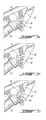
- FIGS. 5 a - 5 i are partial side views of the double eccentric cam assembly of FIG. 2 , shown in each of nine different adjustment positions thereof;
- FIG. 6 is a side elevation view of a bicycle with the frame set of FIG. 1 .
- the bicycle frame set of the present disclosure includes a rear wheel suspension system and a main frame, which provides improved adjustability and/or variability of the frame geometry as may be desired in order to best suit or match a rider, type of riding (ex: downhill, cross-country, etc.) and/or the riding conditions.
- a bicycle having such a frame set will also include all other commonly included components, such as wheels, seat, handle bars, gearing, deraille, etc.
- the bicycle frame set 9 comprises a forward main frame section 10 having generally a seat tube 12 , a top tube 13 , a head or steering tube 14 , a down tube 15 , and a bottom bracket 16 disposed at a lower end of the down tube 15 .
- the bicycle frame set 9 is intended to be used as a mountain bicycle, and includes a rear wheel suspension 20 which is pivotally mounted to the main frame 10 as will be seen below.
- the rear wheel suspension system 20 is pivotally attached to the main frame 10 by at least two spaced-apart pivot points, which as seen in the embodiment depicted in FIG. 1 include lower pivot 30 and upper pivot 32 .
- the rear wheel suspension system 20 generally comprises at least the following pivotally interconnected links: a swing arm (or chain stay) member 22 ; a seat stay member 28 ; and a first upper link member 24 .
- a second or intermediate upper link member 35 may also be provided and pivotally interconnected between the seat stay member 28 and the first upper link member 24 .
- the rear wheel suspension system 20 of the depicted embodiment is a single or fixed pivot suspension system, in that the rear wheel moves about a fixed radius arc relative to the lower pivot 30 of the main frame 10 .
- the swing arm 22 is pivotally connected directly to the main frame 10 at a single location, namely lower pivot 30 disposed preferably just above the bottom bracket 16 .
- the first upper link member 24 has an upper end 25 pivotally connected to the top tube 13 of the main frame 10 by top pivot 32 and a lower end 27 which is pivotally connected to a rearward end of a shock absorber 50 .
- the lower end 27 of the first upper link member 24 is also pivotally connected to the seat stay member 28 at its upper end, either directly or via the intermediate link 35 .
- the first link member 24 is pivotable about the top pivot 32 in a generally counter-clockwise direction when viewing the bike as depicted in FIG. 1 , which is opposite the direction of rotation of the swing arm member 22 . Accordingly, as the suspension 20 compresses, thereby compressing and thus shortening the shock absorber 50 , the first upper link member 24 rotates counter-clockwise (when viewed from the right-hand side of the frame, as shown in FIG. 1 ) about the top pivot 32 such that the lower end 27 moves in a forward direction relative to the main frame 10 .
- the swing arm 22 has a lower forward end 23 which is pivotally connected with the main frame 10 by lower pivot 30 .
- the seat stay member 28 is pivotally connected to the swing arm 22 at its rear end 29 and includes a rear wheel dropout 26 for receiving and engaging a rear wheel axle.
- the opposed, upper, end of the seat stay member 28 is pivotally connected to the first link member 24 , either directly or via the intermediate link 35 as noted above.
- the forward end of the shock absorber 50 is mounted to at least one of the tubes of the main frame 10 , such as but not limited to the top tube 13 for example, by a shock mounting bracket 36 fixed in place on the said tube of the main frame.
- the forward end of the shock absorber 50 is pivotally connected to the shock mounting bracket 36 of the main frame 10 by a double eccentric cam assembly 40 of the present disclosure, as will now be described in further detail.
- the double eccentric cam assembly 40 is provided between the shock absorber 50 and the main frame, it is to be understood that the double eccentric cam assembly 40 described herein may be disposed at any pivot point between the rear suspension 20 and the main frame 10 , such as at the lower pivot 30 for example, and/or alternately at any pivot joint between the links of the rear suspension 20 itself.
- the double eccentric cam assembly 40 comprises generally an inner eccentric cam 42 and an outer eccentric cam 44 , which mate together to form an adjustable pivot joint assembly which interconnects at least one component of the rear suspension system 20 (in this case the forward end of the shock absorber 50 ) and the main frame portion 10 of the bicycle frame set 9 .
- These cams 42 , 44 , or “chips”, are removably mounted and engaged together such as to permit their selective replacement and/or rotational position relative to each other, in order to be able to vary characteristics of the bicycle such as its overall geometry, suspension travel, suspension rate, maximum force at bottom-out of the suspension, etc.
- a fastener 46 passes through an eccentrically disposed aperture or hole 51 (see FIG.
- the shock absorber 50 is pivotally connected to the fastener 46 of the assembly 40 , which thereby forms an axle defining an axis of rotation 41 (see FIG. 4 ) about which the shock absorber 50 pivots at its upper end.
- the inner eccentric cam 42 is received within a corresponding shaped cavity or opening 45 formed in the outwardly facing surface 47 of the outer eccentric cam 44 , and is retained in place therewithin by the fastener 46 .
- the perimeter of the inner eccentric cam 42 and the perimeter of the opening 45 of the outer eccentric cam 44 within which it is received have a corresponding and complementary shape, so that the inner eccentric cam 42 can be nested in the cavity or opening 45 of the eccentric cam 44 as seen in FIG. 3 .
- the inner eccentric cam 42 is not able to rotate (ex: about the transverse axis defined through the fastener 46 ).
- the outer eccentric cam 44 is received within a correspondingly sized and shaped opening 49 (see FIG. 4 ) in the shock mounting bracket 36 . As such, much as per the nested inner and outer eccentric cams, when the outer eccentric cam 44 is located in position within the corresponding opening 49 in the shock mounting bracket 36 , the outer eccentric cam 44 cannot rotate therewithin.
- the opening 45 in the outer eccentric cam 44 is eccentrically disposed within the body of the outer cam 44 relative to its outer perimeter (i.e. the opening 45 is not centered relative to the outer perimeter).
- the outer perimeter of the outer cam 44 is square in shape.
- the outer perimeter of the inner cam 42 is also square in shape.
- the aperture or hole 51 in the inner eccentric cam 42 which receives the fastener 46 therethrough and which defines the axis of rotation 41 (see FIG. 4 ) of the double eccentric cam assembly 40 and therefore of the shock mounting pivot with the main frame, is also eccentrically disposed within the inner cam 42 relative to the outer perimeter of the inner cam 42 (i.e. the hole 51 is not centered relative to the outer perimeter of the inner cam 42 , which itself is not centered relative to the outer perimeter of the outer cam 44 ).
- the precise location of the fastener 46 which defines an axle through which extends the transverse axis of rotation 41 about which the shock absorber 50 pivots, relative to the surrounding mounting flange of the shock mounting bracket 36 (and therefore relative to the tube of the main frame 10 to which it is fixed) is variable. More particularly, by rotating one or both of the inner and outer eccentric cams 42 , 44 , the location of the axis of rotation 41 of the forward shock pivot, defined through the center of the fastener 46 , can be adjusted away from a central or “neutral” position (as shown in FIG.
- the double eccentric cam assembly 40 disclosed herein could also be positioned, at other pivoting joints of the frame set and its rear wheel suspension system, in addition to or in lieu of being disposed between the shock absorber 50 and the main frame 10 .
- a double eccentric cam assembly 40 could also be provided at the lower pivot point 30 between the main frame 10 and the rear suspension system 20 , or alternately within the suspension system 20 itself such as at the rearward pivot between the swing arm 22 and the seat stay 28 , between the seat stay 28 and the first upper link member 24 (or the intermediate link member 35 ), and/or between the first upper link member 24 and the bottom of the shock absorber 50 .
- AD of the above may also be possible.
- the inner and outer eccentric cams 42 and 44 are four-sided and have a square/diamond shape, and therefore in this embodiment each of the square cams or chips 42 , 44 has four different positions each (i.e. one for each edge of the perimeter of the respective cams), and moving each from one position to the next involves rotating it by 90 degrees.
- the two square eccentric cams 42 , 44 together permit up to nine possible total combinations and therefore provide the double eccentric cam assembly 40 with nine total different relative pivot axis positions, which according provide nine different corresponding suspension positions.
- FIGS. 5 a - 5 i As can be readily seen in FIGS.
- the relative position of the pivot axis 41 of the assembly 40 is disposed in a slightly different location depending on the selected configuration (i.e. rotational position or orientation) of the inner and outer eccentric cams. 42 , 44 .
- Table 2 shows the details of each of the nine double eccentric cam assembly positions shown in FIGS. 5 a - 5 i , and reveals how each of these nine pivot axis positions varies the relative geometry of the frame set 9 .
- the rear wheel suspension 20 may thus be adjusted and adapted as necessary to suit certain race courses, or to suit varying riders and skill levels.
- the eccentric cams 42 , 44 may have any one of a diamond shape, a hexagonal shape, a triangular shape, pentagonal shape, etc.
- a circularly shaped eccentric cam may also be used, care would have to be taken to ensure that anti-rotational means (such as gear teeth, projecting tangs, etc.) are provided such as to prevent any unwanted rotation thereof relative to the other cam with which it is nested and/or relative to the mounting bracket of the frame.
- anti-rotational means such as gear teeth, projecting tangs, etc.
- the advantage of such a circular cam is that it may provide many more possible adjustment positions.
Landscapes
- Engineering & Computer Science (AREA)
- Mechanical Engineering (AREA)
- Axle Suspensions And Sidecars For Cycles (AREA)
Abstract
Description
| TABLE 1 |
| Geometry table following 3 mm eccentric cam adjustment at shock |
| Head angle | BBH | Seat angle | Rear travel | Bottom out | |
| Position | (degrees) | (mm) | (degrees) | (Y) (mm) | force (lbs) |
| 1 (default) | 68 | 343.3 | 74.07 | 132.97 | 712 |
| 2 | 68.44 | 347.7 | 74.44 | 136.08 | 688 |
| 3 | 68.8 | 351.8 | 74.8 | 135.7 | 670 |
| 4 | 68.4 | 347.5 | 74.4 | 133.07 | 693 |
| TABLE 2 | ||||||
| Seat | Bottom | Head | ||||
| Fig- | tube | Bracket | tube | Ride | ||
| ure | Setting | angle | Drop | angle | Optimiza- | Rider |
| No. | No. | (degrees) | (mm) | (degrees) | | Weight |
| 5a |
| 1 | 74.5 | 0 | 67.5 | Neutral | Neutral | |
| (default | (mid- | |||||
| midpoint) | point) | |||||
| 5b | 2 | 75.34 | −9.8 | 68.34 | | Neutral |
| 5c | ||||||
| 3 | 74.92 | −4.9 | 67.92 | | | |
| Climbing | ||||||
| 5d | ||||||
| 4 | 74.45 | −0.43 | 67.46 | Neutral | Lighter | |
| 5e | 5 | 74.04 | 5.36 | 67.04 | Light | Lighter |
| Descending | ||||||
| 5f | 6 | 73.62 | 10.27 | 66.62 | Aggressive | |
| Descending | ||||||
| 5g | ||||||
| 7 | 74.08 | 4.93 | 67.08 | Less | Heavier | |
| Aggressive | ||||||
| Descending | ||||||
| 5h | 8 | 74.51 | 0.1 | 67.51 | Neutral | Heavi- |
| est | ||||||
| 5i | 9 | 74.92 | −4.97 | 67.92 | Light | Heavier |
| Climbing | ||||||
Claims (18)
Priority Applications (1)
| Application Number | Priority Date | Filing Date | Title |
|---|---|---|---|
| US13/756,769 US8931794B2 (en) | 2012-02-03 | 2013-02-01 | Bicycle frame with adjustable geometry |
Applications Claiming Priority (2)
| Application Number | Priority Date | Filing Date | Title |
|---|---|---|---|
| US201261594794P | 2012-02-03 | 2012-02-03 | |
| US13/756,769 US8931794B2 (en) | 2012-02-03 | 2013-02-01 | Bicycle frame with adjustable geometry |
Publications (2)
| Publication Number | Publication Date |
|---|---|
| US20130214507A1 US20130214507A1 (en) | 2013-08-22 |
| US8931794B2 true US8931794B2 (en) | 2015-01-13 |
Family
ID=48981702
Family Applications (1)
| Application Number | Title | Priority Date | Filing Date |
|---|---|---|---|
| US13/756,769 Active 2033-07-14 US8931794B2 (en) | 2012-02-03 | 2013-02-01 | Bicycle frame with adjustable geometry |
Country Status (1)
| Country | Link |
|---|---|
| US (1) | US8931794B2 (en) |
Cited By (5)
| Publication number | Priority date | Publication date | Assignee | Title |
|---|---|---|---|---|
| DE102015106905A1 (en) | 2015-05-04 | 2016-11-10 | Rose Bikes Gmbh | Bicycle with rear suspension |
| US10850799B2 (en) | 2018-04-05 | 2020-12-01 | Specialized Bicycle Components, Inc. | Adjustable bicycle suspension |
| US20220153381A1 (en) * | 2020-11-18 | 2022-05-19 | Yeti Cycling, Llc | Integrated motor mount and suspension pivot |
| US11780528B2 (en) | 2020-05-21 | 2023-10-10 | Specialized Bicycle Components, Inc. | Adjustable head angle bicycles |
| US20240059369A1 (en) * | 2022-08-19 | 2024-02-22 | Ltp Sports Group Inc. | Two-wheeled vehicle having rear suspension with adjustable leverage curve progression |
Families Citing this family (11)
| Publication number | Priority date | Publication date | Assignee | Title |
|---|---|---|---|---|
| US9216791B2 (en) * | 2011-03-14 | 2015-12-22 | Christopher Hudec | Bicycle suspension system |
| WO2012122634A1 (en) * | 2011-03-14 | 2012-09-20 | Cmh Plus Holdings Ltd. | Bicycle suspension system |
| USD719488S1 (en) * | 2013-07-03 | 2014-12-16 | Specialized Bicycle Components, Inc. | Bicycle frame |
| US9156521B2 (en) | 2013-12-23 | 2015-10-13 | Wayne Lumpkin | Bicycle frame rear suspension with flexing frame segment |
| USD774970S1 (en) | 2015-02-27 | 2016-12-27 | Specialized Bicycle Components, Inc. | Bicycle frame |
| PL234547B1 (en) * | 2015-05-25 | 2020-03-31 | Engineo Spolka Z Ograniczona Odpowiedzialnoscia | Shock-absorbed bicycle frame |
| KR101738044B1 (en) * | 2015-11-02 | 2017-05-29 | 현대자동차주식회사 | Structure of pedal having integral hinge bracket |
| CN105460144A (en) * | 2015-12-28 | 2016-04-06 | 天津博利自行车有限公司 | Foldable frame |
| CN109018118A (en) * | 2018-09-13 | 2018-12-18 | 黄承志 | A kind of mountain bike |
| CA209519S (en) * | 2021-07-22 | 2023-07-06 | Decathlon Sa | Bicycle\motorcycle frame |
| EP4438453B1 (en) * | 2023-03-30 | 2026-05-13 | Orbea, S. Coop. | System and method for modifying the geometry of a bicycle |
Citations (23)
| Publication number | Priority date | Publication date | Assignee | Title |
|---|---|---|---|---|
| US676629A (en) * | 1900-08-24 | 1901-06-18 | Jehu C Moore | Crank mechanism for velocipedes. |
| US697944A (en) * | 1900-01-24 | 1902-04-15 | Frederic I Johnson | Crank-shaft bearing of bicycles. |
| US4684143A (en) * | 1985-04-05 | 1987-08-04 | Yasunori Sato | Two-wheeled vehicle with hydraulic transmission |
| US4697469A (en) * | 1985-04-01 | 1987-10-06 | Bridgestone Cycle Co., Ltd. | Stepless speed change device |
| US4712450A (en) * | 1985-02-09 | 1987-12-15 | Bridgestone Cycle Co., Ltd. | Stepless speed change device |
| US4732054A (en) * | 1985-06-27 | 1988-03-22 | Bridgestone Cycle Co., Ltd. | Stepless speed change device |
| US4793208A (en) * | 1985-03-13 | 1988-12-27 | Societe Look | Crank-gear for bicycle or similar locomotion vehicle |
| US4916974A (en) * | 1987-02-21 | 1990-04-17 | Bridgestone Cycle Co., Ltd. | Stepless speed change device |
| US5161430A (en) * | 1990-05-18 | 1992-11-10 | Febey Richard W | Pedal stroke range adjusting device |
| US5387000A (en) * | 1992-07-22 | 1995-02-07 | Sato; Yasunori | Hydraulic drive system for bicycles and the like |
| US5516132A (en) * | 1994-07-22 | 1996-05-14 | Simkins; Barry A. | Variable-speed transmission |
| US5879017A (en) * | 1998-05-14 | 1999-03-09 | Debruin; Jeffery N. | Pedaling efficiency |
| US6073950A (en) * | 1997-10-28 | 2000-06-13 | Busby; James S. | Bicycle with crank assembly suspension system |
| US6099010A (en) * | 1997-10-28 | 2000-08-08 | Gt Bicycles, Inc. | Bicycle with crank assembly suspension system |
| US6474193B1 (en) * | 1999-03-25 | 2002-11-05 | Sinties Scientific, Inc. | Pedal crank |
| US6895834B1 (en) * | 2002-10-04 | 2005-05-24 | Racer-Mate, Inc. | Adjustable crank for bicycles |
| US20080296966A1 (en) * | 2005-10-10 | 2008-12-04 | In Sup Choi | Bicycle of Shaking Equipment |
| US7854440B2 (en) * | 2007-06-21 | 2010-12-21 | Dagg | Bicycle adapted to different forms of cycling |
| US7891688B2 (en) * | 2009-03-09 | 2011-02-22 | Specialized Bicycle Components, Inc. | Bicycle frame with articulating linkage mounting arrangement |
| US7918474B2 (en) * | 2009-02-20 | 2011-04-05 | Trek Bicycle Corporation | Bicycle dropout assembly |
| US8430415B2 (en) * | 2010-03-16 | 2013-04-30 | Sotto Group LLC | Bicycle rear suspension system |
| US8561498B2 (en) * | 2008-02-12 | 2013-10-22 | Niner, Inc. | Bicycle eccentric bottom bracket |
| US20140049020A1 (en) * | 2012-08-15 | 2014-02-20 | Cycling Sports Group, Inc. | Insert for adjustment of operational characteristic of a bicycle and bicycle portion with insert |
-
2013
- 2013-02-01 US US13/756,769 patent/US8931794B2/en active Active
Patent Citations (24)
| Publication number | Priority date | Publication date | Assignee | Title |
|---|---|---|---|---|
| US697944A (en) * | 1900-01-24 | 1902-04-15 | Frederic I Johnson | Crank-shaft bearing of bicycles. |
| US676629A (en) * | 1900-08-24 | 1901-06-18 | Jehu C Moore | Crank mechanism for velocipedes. |
| US4712450A (en) * | 1985-02-09 | 1987-12-15 | Bridgestone Cycle Co., Ltd. | Stepless speed change device |
| US4793208A (en) * | 1985-03-13 | 1988-12-27 | Societe Look | Crank-gear for bicycle or similar locomotion vehicle |
| US4697469A (en) * | 1985-04-01 | 1987-10-06 | Bridgestone Cycle Co., Ltd. | Stepless speed change device |
| US4684143A (en) * | 1985-04-05 | 1987-08-04 | Yasunori Sato | Two-wheeled vehicle with hydraulic transmission |
| US4732054A (en) * | 1985-06-27 | 1988-03-22 | Bridgestone Cycle Co., Ltd. | Stepless speed change device |
| US4916974A (en) * | 1987-02-21 | 1990-04-17 | Bridgestone Cycle Co., Ltd. | Stepless speed change device |
| US5161430A (en) * | 1990-05-18 | 1992-11-10 | Febey Richard W | Pedal stroke range adjusting device |
| US5387000A (en) * | 1992-07-22 | 1995-02-07 | Sato; Yasunori | Hydraulic drive system for bicycles and the like |
| US5516132A (en) * | 1994-07-22 | 1996-05-14 | Simkins; Barry A. | Variable-speed transmission |
| US6073950A (en) * | 1997-10-28 | 2000-06-13 | Busby; James S. | Bicycle with crank assembly suspension system |
| US6099010A (en) * | 1997-10-28 | 2000-08-08 | Gt Bicycles, Inc. | Bicycle with crank assembly suspension system |
| US5879017A (en) * | 1998-05-14 | 1999-03-09 | Debruin; Jeffery N. | Pedaling efficiency |
| US6474193B1 (en) * | 1999-03-25 | 2002-11-05 | Sinties Scientific, Inc. | Pedal crank |
| US6820517B1 (en) * | 1999-03-25 | 2004-11-23 | Scifit Systems, Inc. | Pedal crank |
| US6895834B1 (en) * | 2002-10-04 | 2005-05-24 | Racer-Mate, Inc. | Adjustable crank for bicycles |
| US20080296966A1 (en) * | 2005-10-10 | 2008-12-04 | In Sup Choi | Bicycle of Shaking Equipment |
| US7854440B2 (en) * | 2007-06-21 | 2010-12-21 | Dagg | Bicycle adapted to different forms of cycling |
| US8561498B2 (en) * | 2008-02-12 | 2013-10-22 | Niner, Inc. | Bicycle eccentric bottom bracket |
| US7918474B2 (en) * | 2009-02-20 | 2011-04-05 | Trek Bicycle Corporation | Bicycle dropout assembly |
| US7891688B2 (en) * | 2009-03-09 | 2011-02-22 | Specialized Bicycle Components, Inc. | Bicycle frame with articulating linkage mounting arrangement |
| US8430415B2 (en) * | 2010-03-16 | 2013-04-30 | Sotto Group LLC | Bicycle rear suspension system |
| US20140049020A1 (en) * | 2012-08-15 | 2014-02-20 | Cycling Sports Group, Inc. | Insert for adjustment of operational characteristic of a bicycle and bicycle portion with insert |
Cited By (9)
| Publication number | Priority date | Publication date | Assignee | Title |
|---|---|---|---|---|
| DE102015106905A1 (en) | 2015-05-04 | 2016-11-10 | Rose Bikes Gmbh | Bicycle with rear suspension |
| DE102015106905B4 (en) * | 2015-05-04 | 2017-06-29 | Rose Bikes Gmbh | Bicycle with rear suspension |
| US10850799B2 (en) | 2018-04-05 | 2020-12-01 | Specialized Bicycle Components, Inc. | Adjustable bicycle suspension |
| US11420707B2 (en) | 2018-04-05 | 2022-08-23 | Specialized Bicycle Components, Inc. | Adjustable bicycle suspension |
| US11780528B2 (en) | 2020-05-21 | 2023-10-10 | Specialized Bicycle Components, Inc. | Adjustable head angle bicycles |
| US12065213B2 (en) | 2020-05-21 | 2024-08-20 | Specialized Bicycle Components, Inc. | Adjustable head angle bicycles |
| US20220153381A1 (en) * | 2020-11-18 | 2022-05-19 | Yeti Cycling, Llc | Integrated motor mount and suspension pivot |
| US12384484B2 (en) * | 2020-11-18 | 2025-08-12 | Yeti Cycling, Llc | Integrated motor mount and suspension pivot |
| US20240059369A1 (en) * | 2022-08-19 | 2024-02-22 | Ltp Sports Group Inc. | Two-wheeled vehicle having rear suspension with adjustable leverage curve progression |
Also Published As
| Publication number | Publication date |
|---|---|
| US20130214507A1 (en) | 2013-08-22 |
Similar Documents
| Publication | Publication Date | Title |
|---|---|---|
| US20130214507A1 (en) | Bicycle frame with adjustable geometry | |
| US9242693B2 (en) | Bicycle rear suspension | |
| CA2538467C (en) | Bicycle with rear suspension | |
| US8851498B2 (en) | Adjustable geometry bicycle rear wheel suspension system | |
| US10106221B2 (en) | Bicycle rear wheel suspension system | |
| EP4163197B1 (en) | Bicycle rear suspension system | |
| US8459680B2 (en) | Bicycle frame | |
| US6164676A (en) | Variable reduction cross-linkage for rear suspension bicycle | |
| US20240367750A1 (en) | Bicycle Rear Suspension | |
| AU2012228895A1 (en) | Bicycle suspension system | |
| ES2586706T3 (en) | Bicycle rear wheel suspension |
Legal Events
| Date | Code | Title | Description |
|---|---|---|---|
| AS | Assignment |
Owner name: INDUSTRIES RAD INC., CANADA Free format text: ASSIGNMENT OF ASSIGNORS INTEREST;ASSIGNOR:O'CONNOR, D'ARCY;REEL/FRAME:030815/0382 Effective date: 20130501 |
|
| STCF | Information on status: patent grant |
Free format text: PATENTED CASE |
|
| MAFP | Maintenance fee payment |
Free format text: PAYMENT OF MAINTENANCE FEE, 4TH YEAR, LARGE ENTITY (ORIGINAL EVENT CODE: M1551) Year of fee payment: 4 |
|
| MAFP | Maintenance fee payment |
Free format text: PAYMENT OF MAINTENANCE FEE, 8TH YEAR, LARGE ENTITY (ORIGINAL EVENT CODE: M1552); ENTITY STATUS OF PATENT OWNER: LARGE ENTITY Year of fee payment: 8 |
|
| AS | Assignment |
Owner name: WELLS FARGO CAPITAL FINANCE CORPORATION CANADA, CANADA Free format text: SECURITY INTEREST;ASSIGNOR:INDUSTRIES RAD INC.;REEL/FRAME:062196/0567 Effective date: 20221209 |
|
| AS | Assignment |
Owner name: 9539-5927 QUEBEC INC., CANADA Free format text: ASSIGNMENT OF ASSIGNORS INTEREST;ASSIGNOR:INDUSTRIES RAD INC.;REEL/FRAME:071076/0104 Effective date: 20250509 |
|
| AS | Assignment |
Owner name: 9539-5927 QUEBEC INC., CANADA Free format text: CORRECTIVE ASSIGNMENT TO CORRECT THE RECEIVING PARTY ADDRESS PREVIOUSLY RECORDED AT REEL: 71076 FRAME: 104. ASSIGNOR(S) HEREBY CONFIRMS THE ASSIGNMENT;ASSIGNOR:INDUSTRIES RAD INC.;REEL/FRAME:071545/0871 Effective date: 20250509 |
|
| AS | Assignment |
Owner name: SPORTS CHAOS INC., CANADA Free format text: CHANGE OF NAME;ASSIGNOR:9539-5927 QUEBEC INC.;REEL/FRAME:074439/0927 Effective date: 20250509 |
|
| AS | Assignment |
Owner name: CAISSE DESJARDINS DE LA PRARIE, CANADA Free format text: SECURITY INTEREST;ASSIGNOR:SPORTS CHAOS INC.;REEL/FRAME:074497/0849 Effective date: 20260409 |