US8930795B1 - Methods for slicing dynamically modulated symbols - Google Patents
Methods for slicing dynamically modulated symbols Download PDFInfo
- Publication number
- US8930795B1 US8930795B1 US12/910,807 US91080710A US8930795B1 US 8930795 B1 US8930795 B1 US 8930795B1 US 91080710 A US91080710 A US 91080710A US 8930795 B1 US8930795 B1 US 8930795B1
- Authority
- US
- United States
- Prior art keywords
- slicer
- slicing
- symbols
- dbf
- modulation
- Prior art date
- Legal status (The legal status is an assumption and is not a legal conclusion. Google has not performed a legal analysis and makes no representation as to the accuracy of the status listed.)
- Active, expires
Links
- 238000000034 method Methods 0.000 title claims abstract description 73
- 230000001186 cumulative effect Effects 0.000 claims description 5
- 238000010586 diagram Methods 0.000 description 21
- 101000831175 Homo sapiens Mitochondrial import inner membrane translocase subunit TIM16 Proteins 0.000 description 12
- 102100024285 Mitochondrial import inner membrane translocase subunit TIM16 Human genes 0.000 description 12
- 230000003044 adaptive effect Effects 0.000 description 5
- 239000000284 extract Substances 0.000 description 5
- 230000007246 mechanism Effects 0.000 description 2
- 238000012986 modification Methods 0.000 description 2
- 230000004048 modification Effects 0.000 description 2
- 238000013139 quantization Methods 0.000 description 2
- 230000006978 adaptation Effects 0.000 description 1
- 230000005540 biological transmission Effects 0.000 description 1
- 230000010354 integration Effects 0.000 description 1
- 239000000463 material Substances 0.000 description 1
Images


Classifications
-
- H—ELECTRICITY
- H04—ELECTRIC COMMUNICATION TECHNIQUE
- H04L—TRANSMISSION OF DIGITAL INFORMATION, e.g. TELEGRAPHIC COMMUNICATION
- H04L27/00—Modulated-carrier systems
- H04L27/0008—Modulated-carrier systems arrangements for allowing a transmitter or receiver to use more than one type of modulation
-
- H—ELECTRICITY
- H04—ELECTRIC COMMUNICATION TECHNIQUE
- H04L—TRANSMISSION OF DIGITAL INFORMATION, e.g. TELEGRAPHIC COMMUNICATION
- H04L1/00—Arrangements for detecting or preventing errors in the information received
-
- H—ELECTRICITY
- H04—ELECTRIC COMMUNICATION TECHNIQUE
- H04L—TRANSMISSION OF DIGITAL INFORMATION, e.g. TELEGRAPHIC COMMUNICATION
- H04L1/00—Arrangements for detecting or preventing errors in the information received
- H04L1/0001—Systems modifying transmission characteristics according to link quality, e.g. power backoff
- H04L1/0002—Systems modifying transmission characteristics according to link quality, e.g. power backoff by adapting the transmission rate
- H04L1/0003—Systems modifying transmission characteristics according to link quality, e.g. power backoff by adapting the transmission rate by switching between different modulation schemes
-
- H—ELECTRICITY
- H04—ELECTRIC COMMUNICATION TECHNIQUE
- H04L—TRANSMISSION OF DIGITAL INFORMATION, e.g. TELEGRAPHIC COMMUNICATION
- H04L1/00—Arrangements for detecting or preventing errors in the information received
- H04L1/0001—Systems modifying transmission characteristics according to link quality, e.g. power backoff
- H04L1/0036—Systems modifying transmission characteristics according to link quality, e.g. power backoff arrangements specific to the receiver
-
- H—ELECTRICITY
- H04—ELECTRIC COMMUNICATION TECHNIQUE
- H04L—TRANSMISSION OF DIGITAL INFORMATION, e.g. TELEGRAPHIC COMMUNICATION
- H04L25/00—Baseband systems
- H04L25/02—Details ; arrangements for supplying electrical power along data transmission lines
- H04L25/03—Shaping networks in transmitter or receiver, e.g. adaptive shaping networks
- H04L25/03006—Arrangements for removing intersymbol interference
- H04L25/03012—Arrangements for removing intersymbol interference operating in the time domain
- H04L25/03019—Arrangements for removing intersymbol interference operating in the time domain adaptive, i.e. capable of adjustment during data reception
- H04L25/03057—Arrangements for removing intersymbol interference operating in the time domain adaptive, i.e. capable of adjustment during data reception with a recursive structure
-
- H—ELECTRICITY
- H04—ELECTRIC COMMUNICATION TECHNIQUE
- H04L—TRANSMISSION OF DIGITAL INFORMATION, e.g. TELEGRAPHIC COMMUNICATION
- H04L25/00—Baseband systems
- H04L25/02—Details ; arrangements for supplying electrical power along data transmission lines
- H04L25/03—Shaping networks in transmitter or receiver, e.g. adaptive shaping networks
- H04L25/03006—Arrangements for removing intersymbol interference
- H04L25/03012—Arrangements for removing intersymbol interference operating in the time domain
- H04L25/03114—Arrangements for removing intersymbol interference operating in the time domain non-adaptive, i.e. not adjustable, manually adjustable, or adjustable only during the reception of special signals
- H04L25/03146—Arrangements for removing intersymbol interference operating in the time domain non-adaptive, i.e. not adjustable, manually adjustable, or adjustable only during the reception of special signals with a recursive structure
-
- H—ELECTRICITY
- H04—ELECTRIC COMMUNICATION TECHNIQUE
- H04L—TRANSMISSION OF DIGITAL INFORMATION, e.g. TELEGRAPHIC COMMUNICATION
- H04L25/00—Baseband systems
- H04L25/02—Details ; arrangements for supplying electrical power along data transmission lines
- H04L25/06—DC level restoring means; Bias distortion correction ; Decision circuits providing symbol by symbol detection
- H04L25/061—DC level restoring means; Bias distortion correction ; Decision circuits providing symbol by symbol detection providing hard decisions only; arrangements for tracking or suppressing unwanted low frequency components, e.g. removal of DC offset
- H04L25/062—Setting decision thresholds using feedforward techniques only
-
- H—ELECTRICITY
- H04—ELECTRIC COMMUNICATION TECHNIQUE
- H04L—TRANSMISSION OF DIGITAL INFORMATION, e.g. TELEGRAPHIC COMMUNICATION
- H04L27/00—Modulated-carrier systems
- H04L27/0012—Modulated-carrier systems arrangements for identifying the type of modulation
-
- H—ELECTRICITY
- H03—ELECTRONIC CIRCUITRY
- H03M—CODING; DECODING; CODE CONVERSION IN GENERAL
- H03M13/00—Coding, decoding or code conversion, for error detection or error correction; Coding theory basic assumptions; Coding bounds; Error probability evaluation methods; Channel models; Simulation or testing of codes
- H03M13/03—Error detection or forward error correction by redundancy in data representation, i.e. code words containing more digits than the source words
- H03M13/05—Error detection or forward error correction by redundancy in data representation, i.e. code words containing more digits than the source words using block codes, i.e. a predetermined number of check bits joined to a predetermined number of information bits
- H03M13/09—Error detection only, e.g. using cyclic redundancy check [CRC] codes or single parity bit
-
- H—ELECTRICITY
- H04—ELECTRIC COMMUNICATION TECHNIQUE
- H04L—TRANSMISSION OF DIGITAL INFORMATION, e.g. TELEGRAPHIC COMMUNICATION
- H04L25/00—Baseband systems
- H04L25/02—Details ; arrangements for supplying electrical power along data transmission lines
- H04L25/03—Shaping networks in transmitter or receiver, e.g. adaptive shaping networks
- H04L25/03006—Arrangements for removing intersymbol interference
- H04L2025/0335—Arrangements for removing intersymbol interference characterised by the type of transmission
- H04L2025/03356—Baseband transmission
- H04L2025/03363—Multilevel
-
- H—ELECTRICITY
- H04—ELECTRIC COMMUNICATION TECHNIQUE
- H04L—TRANSMISSION OF DIGITAL INFORMATION, e.g. TELEGRAPHIC COMMUNICATION
- H04L5/00—Arrangements affording multiple use of the transmission path
- H04L5/0001—Arrangements for dividing the transmission path
- H04L5/0003—Two-dimensional division
- H04L5/0005—Time-frequency
- H04L5/0007—Time-frequency the frequencies being orthogonal, e.g. OFDM(A) or DMT
-
- H—ELECTRICITY
- H04—ELECTRIC COMMUNICATION TECHNIQUE
- H04L—TRANSMISSION OF DIGITAL INFORMATION, e.g. TELEGRAPHIC COMMUNICATION
- H04L5/00—Arrangements affording multiple use of the transmission path
- H04L5/003—Arrangements for allocating sub-channels of the transmission path
- H04L5/0044—Allocation of payload; Allocation of data channels, e.g. PDSCH or PUSCH
Definitions
- a transmitter transmits a packet comprising symbols over a channel to a receiver.
- the symbols are modulated according to the data they carry, such that symbols carrying different data types may be modulated with different modulations.
- the different modulations used for successive symbols within the same packet are selected from a subset of the same symbol set, or at least from partially overlapping subsets of the same symbol set.
- a single packet may include X symbols modulated using PAM4, then Y symbols modulated using PAM8, then Z symbols modulated using PAM16, and then again X symbols modulated using PAM4.
- the receiver should determine the proper modulation for decoding each symbol or set of symbols.
- the receiver should demodulate the first X symbols using a PAM4 slicer, then demodulate the next Y symbols using a PAM8 slicer, then demodulate the next Z symbols using a PAM16 slicer, and then demodulate the last X symbols using the PAM4 slicer.
- the receiver in order for the receiver to properly decode symbols of different modulations within the same packet, the receiver should know the symbol's modulation and select the proper slicer.
- the symbols' modulations are unknown to the receiver before slicing the symbols, and thus one or more of the methods discussed below are utilized to improve the receiver's performance.
- a system transmits data frames from a transmitter to a receiver over a channel.
- the system uses signal modulation to increase data transfer rates. For example, Pulse Amplitude Modulation (PAM), which divides an analog signal into a finite number of levels, each associated with a digital value, such as four level PAM modulation (PAM4).
- PAM Pulse Amplitude Modulation
- a Decision Based Filter may be used on the analog signal to reduce the probability of error.
- the DBF may require information regarding the type of modulation and values of the symbols entering the receiver, for example slicing results based on PAM4 or PAM8 modulations.
- the DBF performances may be further improved using slicing error associated with the slicing results.
- the receiver includes an Analog Front End (AFE), a DBF, a slicer, and a Physical Coding Sublayer (PCS).
- AFE Analog Front End
- the slicer coverts the analog signal, received from the AFE into slicing results, which are digital representations of the symbols, using an appropriate slicing function.
- the slicing results are fed to a PCS, which parses the data frames and extracts information such as frame headers, frame tail, frame payload and frame modulation information.
- the PCS may determine the modulation used and indicate the slicer of which slicing function to use.
- the slicer may then provide the slicing results from the indicated slicer to the DBF.
- the slicer may additionally provide slicing errors associated with the slicing results, for example a one-bit symbol indicating whether the analog level of the symbol is below or above the slicing level. Then the DBF generates the appropriate output and adds it to the incoming analog signal from the AFE.
- FIG. 1A illustrates one embodiment of a system for sending and receiving frames
- FIG. 2A illustrates one embodiment of a system for sending and receiving frames
- FIG. 3A illustrates one embodiment of a system for sending and receiving frames
- FIG. 4A illustrates one embodiment of a system for sending and receiving frames
- FIG. 5A is a flow diagram illustrating a method for reducing error propagation
- FIG. 5B is a flow diagram illustrating a method for processing frames
- FIG. 5C is a flow diagram illustrating a method for processing frames and reducing error propagation
- FIG. 5D is a flow diagram illustrating a method for processing frames
- FIG. 6A is a flow diagram illustrating a method for reducing error propagation during processing of a received frame comprising variable symbol-modulation
- FIG. 6B is a flow diagram illustrating a method for reducing error propagation during reception and processing of a received frame.
- references to “one embodiment” or “an embodiment” mean that the feature being referred to may be included in at least one embodiment of the invention. Moreover, separate references to “one embodiment” in this description do not necessarily refer to the same embodiment. Illustrated embodiments are not mutually exclusive, unless so stated and except as will be readily apparent to those of ordinary skill in the art. Thus, the invention may include any variety of combinations and/or integrations of the embodiments described herein.
- flow diagrams illustrate non-limiting embodiment examples of the methods
- block diagrams illustrate non-limiting embodiment examples of the devices. Some operations in the flow diagrams may be described with reference to the embodiments illustrated by the block diagrams. However, the methods of the flow diagrams could be performed by embodiments of the invention other than those discussed with reference to the block diagrams, and embodiments discussed with reference to the block diagrams could perform operations different from those discussed with reference to the flow diagrams. Moreover, although the flow diagrams may depict serial operations, certain embodiments could perform certain operations in parallel and/or in different orders from those depicted.
- slice function is defined as one or more dimensional quantizer that outputs the quantization result and optionally the error between the received signal and the quantization result.
- DBF decision based filter
- the DBF is a non-adaptive Decision Feedback Equalizer (DFE), or a non-adaptive FEXT canceller, fed by the slicing results.
- the DBF is an adaptive DFE, or an adaptive FEXT canceller, fed by the slicing results and the slicing errors.
- the DBF is an adaptive Feed-Forward Equalizer (FFE) fed by the slicing errors for adaptation purpose.
- FFE Feed-Forward Equalizer
- a receiver for packets comprising symbols of at least two different modulations in the same packet includes a fine slicer and a dynamic slicer.
- the fine slicer slices the symbols using all of the symbol-set levels and provides the slicing error, which may include only the direction of the error (i.e. one-bit error).
- the dynamic slicer slices the symbols based on the symbols' estimated modulations.
- the dynamic slicer which belongs to the physical layer and therefore is unaware of the proper required modulation, receives feedback from the coding layer, which is able to determine the proper required modulation.
- the dynamic slicer provides accurate results with the shortest delay.
- the dynamic slicer provides false results.
- the packet includes the following fields: header, packet type defining the payload modulations, payload length, payload data, and CRC.
- the Physical Coding Sublayer features a processing delay that prevents it from adjusting the slicer to the proper packet type before the payload is received. Because the processing delay of the PCS is known, and to be able to use such a PCS with a dynamic slicer, the first few symbols and/or bytes of the payload are modulated with a predetermined modulation scheme that is used until the commands from the PCS are received by the slicer.
- FIG. 1 illustrates one example of a frame 107 A containing payload having a few initial bytes modulated with a predetermined modulation (PAM4), then the following bytes are modulated according to the data (PAM8 and PAM16), and then the tail is modulated again with the predetermined modulation (PAM4).
- PAM4 predetermined modulation
- This initial a priori modulation pattern enables a PCS having a delay longer than the time between the packet type and the payload to control a dynamic slicer.
- the slicer may slice the symbols according to all possible modulations in parallel, it is desirable to forward to a DBF the most accurate results, meaning that the right modulation has to be known as fast as possible.
- a receiver comprises a slicer, a Physical Coding Sublayer (PCS), and a Decision Based Filter (DBF).
- the receiver receives frames including symbols of at least two different modulation orders that use subsets of a symbol superset that essentially equals the highest modulation order.
- the slicer operates slicing functions suitable for the different modulations, and feeds the PCS with slicing results of the slicer suitable for the highest modulation order.
- the PCS identifies frame boundaries and modulation information, which are modulated according to a predetermined modulation order.
- the PCS further uses the identified modulation information to determine the modulation of a nonempty set of dynamically modulated symbols in each frame, and provides the slicer with an indication of which slicer function output to use to feed the DBF.
- FIG. 1 illustrates one embodiment of a system for sending and receiving frames 107 A.
- a frame may include audio, video, messaging, and general data.
- the system includes a transmitter 101 A, a channel 102 , and a receiver.
- the receiver includes an Analog Front End (AFE) 103 , a slicer 104 A, a PCS 105 A, and a DBF 106 A.
- the frames 107 A include symbols of at least two different modulation orders that use subsets of a symbol superset that essentially equals the highest modulation order.
- sentences such as “wherein the different modulations use subsets of the same symbol superset that essentially equal the highest modulation order” mean that the superset may essentially consist of the levels of the highest symbol set, or the superset may comprise the levels of the highest symbol set in addition to few more levels used by one or more of the other modulations, where the few more level are less than a quarter of the total levels.
- the slicer 104 A has slicing functions suitable for the different modulations and feeds the PCS 105 A with slicing results of the slicer 104 A suitable for the highest modulation order.
- slicer 104 A may have PAM4, PAM8, and PAM16 slicing functions and may feed the PCS 105 A with PAM16 slicing results.
- the PCS 105 A identifies the frame boundaries and modulation information based on their predetermined modulation order.
- the PCS 105 A further uses the identified modulation information to determine the modulation of a nonempty set of dynamically modulated symbols in each frame, and provides the slicer 104 A with an indication of which slicer function output to use to feed the DBF 106 A.
- the modulation may be PAM4, PAM8, or PAM16.
- the PCS 105 A identifies the modulation information, reads the modulation information, and indicates to the slicer 104 A, to use PAM8 modulation.
- the DBF 106 A outputs an analog signal, which is summed with the signal output of the AFE 103 , before entering the slicer 104 A.
- the slicer function output includes the slicing results of the indicated slicer function.
- the slicer function output includes slicing errors of the indicated slicer function, and the DBF 106 A uses the slicing error to adapt filter coefficients that feed the slicer 104 A.
- the slicing error consists of direction of the slicing error.
- the slicing error may be a one-bit signal indicating the value “0” when the slicing result is below the slicing function level and the value “1” when the slicing result is above the slicing function level.
- the PCS 105 A further uses the slicing error to correct the slicing result.
- the DBF 106 A improves signal-to-noise-ratio at the slicer 104 A input based on the feeding from the slicer to the DBF 106 A.
- the nonempty set of dynamically modulated symbols includes at least a quarter of the received symbols associated with the received frames.
- a frame may include a header followed by 256 dynamically modulated symbols.
- the PCS 105 A features a delay longer than the time between receiving the modulation information and receiving the first dynamically modulated symbol, and the slicer 104 A feeds a DBF 106 A with the predetermined modulation order results until the slicer 104 A receives the indication of which slicer function output to use to feed the DBF 106 A.
- the receiver communicates with a transmitter 101 A that dynamically modulates at least some of the symbols associated with the frame payload based on the type of data conveyed by each symbol.
- the transmitter 101 A modulates the first three payload symbols of each frame using PAM4 modulation and then modulates the rest of the payload symbols according to their data types.
- the transmitter 101 A is further configured to modulate the dynamically modulated symbols based on properties of the channel 102 to the receiver. For example, the transmitter modulates the dynamically modulated symbols using PAM16 when the distance between the transmitter 101 A and the receiver is short, and PAM8 when the distance between the transmitter 101 A and the receiver is long.
- the transmitter 101 A achieves source coding by selecting different modulations for different symbols based on the symbols' data types.
- the transmitter 101 A modulates video data using PAM16, and control data using PAM4.
- the receiver communicates with a transmitter 101 A that modulates idle time and the frame boundaries according to the predetermined modulation, and modulates the dynamically modulated symbols based on type of data conveyed by each symbol.
- the transmitter 101 A modulates idle time and the frame boundaries using PAM4, and dynamically modulates symbols containing control data using PAM8.
- the frame boundaries include a frame tail, and the slicer 104 A feeds the PCS 105 A with the slicing of the frame tail according to the predetermined modulation.
- the slicer 104 A feeds the PCS with PAM4 tail symbols.
- the slicer 104 A After receiving the indication of which slicer function output to use to feed the DBF, the slicer 104 A provides the PCS with the slicer function according to the indication received from the PCS 105 A.
- most of the time is to be interpreted as more than 50% of the time. In some cases, most of the time is to be interpreted as more than 90% of the time.
- the frame boundaries include a frame header and frame tail
- the modulation information is a field located at one of the frame boundaries.
- the modulation information field describes the modulations of the dynamically modulated symbols as function of the symbol locations in the frame.
- a substantial amount of the modulation information is located at the frame header and the modulation information describes the symbol modulations as function of the symbol locations at the current frame and symbol locations in at least one following frame.
- the frame header stores modulation information describing the symbol modulations as function of the symbol locations at the current frame
- the frame tail stores information modulation describing the symbol modulations as function of the symbol locations in at least one following frame.
- a receiver includes an AFE coupled to a slicer that receives symbols of at least two different modulations.
- the different modulations use subsets of the same symbol superset that essentially equals the highest modulation order. At least some of the symbols are associated with a frame payload and are dynamically modulated.
- the slicer fine slices the symbols using the superset levels, and feeds the fine slicing results and corresponding slicing errors to a PCS.
- the PCS uses the fine slicing results and errors to identify the frame, extracts data describing the symbol modulations as function of the symbol locations in the frame, and feeds the slicer with the extracted symbol modulations. Then, the slicer slices the remaining symbols in the frame payload according to the extracted symbol modulations and feeds a DBF and the PCS with the result.
- FIG. 2 illustrates one embodiment of a system for sending and receiving frames 107 B.
- the system includes a transmitter 101 B, a channel 102 , and a receiver.
- the receiver includes an AFE 103 , a slicer 104 B, a PCS 105 B, and a DBF 106 B.
- the receiver receives symbols of at least two different modulations, where the different modulations are subsets of the same symbol superset that essentially equals the highest modulation order. At least some of the symbols are associated with a frame payload and are dynamically modulated.
- the slicer 104 B fine slices the symbols using the superset levels, and feeds the fine slicing results and corresponding slicing errors to a PCS 105 B.
- slicer 104 B may use a PAM16 slicing function for each slicing result, may feed the PCS 105 B with a 4 bit value slicing result, and a 1 bit value indicating the corresponding slicing error.
- the PCS 105 B uses the fine slicing results and errors to identify the frame, extract data describing the symbol modulations as function of the symbol locations in the frame, and feed the slicer 104 B with the extracted symbol modulations.
- PCS 105 B may use PAM16 slicing results and slicing errors to extract data indicating that the frame payload size is 256 symbols, and symbols starting with a predefined symbol after the header may be dynamically modulated.
- the slicer 104 B slices the remaining symbols in the frame payload according to the extracted symbol modulations, and feeds a DBF 106 B and the PCS 105 B with the result.
- the slicer 104 B may fine slice the first three symbols of the payload using PAM4 slicing function, then continuing with the fourth symbol using PAM8 slicing function.
- the slicer 104 B may feed the PCS 105 B with PAM8 slicing results and slicing errors, and feeds DBF 106 B with PAM8 slicing results.
- the PCS 105 B provides improved slicing results based on the fine slicing results and corresponding slicing errors.
- the slicer 104 B provides the PCS 105 B with the slicer function according to the extracted symbol modulations received from the PCS. For example, a slicer 104 B begins fine slicing symbols in a frame using PAM16.
- the PCS 105 B extracts data indicating that the first three symbols after the header are modulated using PAM4 and sends the modulation to the slicer 104 B.
- the slicer 104 B then provides the PCS 105 B with PAM4 slicing results until the fourth symbol is reached.
- the slicer 104 B feeds the PCS 105 B with the fine slicing results, and the PCS 105 B checks the modulation also after extracting the data describing the symbol modulations as function of the symbol locations in the frame 107 B in order to correct a possible cumulative error.
- the PCS 105 B checks the modulation also after extracting the data describing the symbol modulations as function of the symbol locations in the frame 107 B in order to correct a possible cumulative error.
- FIG. 3 illustrates one embodiment of a system for sending and receiving frames 107 C.
- the system includes a transmitter 101 C, a channel 102 , and a receiver.
- the receiver includes an AFE 103 , a slicer 104 C, a PCS 105 C, and a DBF 106 C.
- the receiver receives symbols of at least two different modulations.
- the different modulations use subsets of the same symbol superset that essentially equals the highest modulation order. At least some of the symbols are associated with a frame payload and are dynamically modulated.
- the slicer 104 C fine slices the symbols using the superset levels, and feeds the fine slicing results and corresponding slicing errors to a PCS 105 C.
- the PCS 105 C uses the fine slicing results and errors to identify the frame, extracts data describing at least some of the symbol modulations as function of the symbol locations in the frame, provides improved slicing results based on the extracted symbol modulations, and feeds the slicer 104 C with the extracted symbol modulations.
- the slicer 104 C further slices at least a quarter of the received symbols, which are associated with the frame, according to the extracted symbol modulations, and feeds a DBF with the result.
- the receiver communicates with a transmitter 101 C that dynamically modulates the at least some of the symbols associated with the frame payload based on type of data conveyed by each symbol.
- the receiver communicates with a transmitter that achieves source coding by selecting different modulations for different symbols based on the symbols' data types.
- the slicing errors consist of the direction of the slicing error.
- the header of the frame 107 C stores the data describing the symbol modulations as a function of the symbol locations in the frame 107 C.
- the header of the frame 107 C stores the data describing the symbol modulations as a function of the symbol locations in the current frame and symbol locations in at least one following frame.
- the header of the frame 107 C stores the data describing the symbol modulations as a function of the symbol locations in the frame 107 C
- the frame's tail stores the data describing the symbol modulations as function of the symbol locations in at least one following frame 107 C.
- FIG. 4 illustrates one embodiment of a system for sending and receiving frames 107 D.
- the system includes a transmitter 101 D, a channel 102 , and a receiver.
- the receiver includes an AFE 103 , a slicer 104 D, a PCS 105 D, and a DBF 106 D.
- Each of most of the received frames includes modulation information modulated according to a predetermined modulation order, and symbols of at least two different modulation orders that are dynamically modulated in accordance with the modulation information.
- the slicer 104 D feeds the PCS 105 D with essentially the minimal combination of slicing results that essentially covers all the modulation orders.
- the PCS 105 D identifies the modulation information, uses the identified modulation information to determine the modulation of the dynamically modulated symbols, and provides the slicer 104 D with an indication of which slicer function output to use to feed the DBF 106 D.
- the slicer includes combined slicing function that produces essentially the minimal combination of slicing results that essentially covers all the modulation orders. In one case, essentially is greater than 80%. In another embodiment, all modulations are subsets of the highest modulation order of the symbols, and therefore the minimal combination of slicing results equals the highest modulation order of the symbols.
- the dynamically modulated symbols include at least a quarter of the received symbols associated with frames 107 D.
- the slicer 104 D after receiving the indication of which slicer function output to use, the slicer 104 D provides the PCS 105 D with the slicing results according to the indication of which slicing function to use, received from the PCS 105 D.
- more than 50% of the time the slicer 104 D feeds the PCS 105 D with the slicing results of the slicing function suitable for the highest modulation order.
- more than 90% of the time the slicer 104 D feeds the PCS 105 D with the slicing results of the slicing function suitable for the highest modulation order.
- the slicer further feeds the DBF with slicing error of the indicated slicer function, and the DBF further uses the slicing error to adapt filter coefficients that feed the slicer.
- the PCS further uses the slicing error to correct the slicing result.
- the DBF improves signal-to-noise-ratio at the slicer input based on the feeding from the slicer to the DBF.
- the dynamically modulated symbols include at least a quarter of the received symbols associated with the received frames.
- FIG. 5A is a flow diagram illustrating a method for reducing error propagation, including the following steps:
- step 501 receiving a frame comprising symbols of at least two different modulation orders that use subsets of a symbol superset that essentially equals the highest modulation order.
- step 502 slicing the received symbols according to the highest modulation order by a slicer having slicing functions suitable for the different modulations.
- step 503 identifying by a PCS frame boundaries, which are modulated according to a predetermined modulation order, and identifying the modulation information.
- step 504 using the identified modulation information for determining the modulation of a nonempty set of dynamically modulated symbols in the received frame.
- step 505 providing the slicer with an indication of which slicer function output to use for feeding a DBF.
- the method further comprising the following optional steps.
- the slicing error consists direction of the slicing error, and further providing by the PCS an improved slicing result based on the slicing error.
- further improving signal-to-noise-ratio at the slicer input based on the feeding from the slicer to the DBF.
- the PCS features a delay longer than the time between receiving the modulation information and receiving the first dynamically modulated symbol, and further feeding the DBF with the predetermined modulation order results until the slicer receives the indication of which slicer function output to use to feed the DBF.
- a transmitter dynamically modulates at least some of the symbols associated with the frame payload based on the type of data conveyed by each symbol.
- modulating the dynamically modulated symbols based on channel properties.
- achieving source coding by selecting different modulations for different symbols based on the symbols' data types.
- a transmitter modulates idle time and the frame boundaries according to the predetermined modulation, and modulates the dynamically modulated symbols based on type of data conveyed by each symbol.
- the frame boundaries include a frame tail
- the slicer feeds the PCS with the slicing results of the frame tail according to the predetermined modulation.
- the PCS after receiving the indication of which slicer function output to use to feed the DBF, further providing the PCS with the slicer function according to the indication received from the PCS.
- the PCS checks the modulation in order to correct a possible cumulative error.
- FIG. 5B is a flow diagram illustrating a method for processing frames, including the following steps:
- step 511 receiving symbols of at least two different modulations by a slicer.
- the different modulations use subsets of the same symbol superset that essentially equals the highest modulation order, and at least some of the symbols are associated with a frame payload and are dynamically modulated.
- step 512 fine slicing the received symbols using the superset levels.
- step 514 using the fine slicing results and errors for identifying the frame, and for extracting data describing the symbol modulations as function of the symbol locations in the frame.
- step 515 feeding the slicer with the extracted symbol modulations.
- step 516 slicing the remaining symbols in the frame payload according to the extracted symbol modulations.
- step 517 feeding a DBF and the PCS with the result.
- FIG. 5C is a flow diagram illustrating a method for processing frames and reducing error propagation, including the following steps:
- step 521 receiving frames, wherein each of most of the frames includes modulation information modulated according to a predetermined modulation order, and symbols of at least two different modulation orders that are dynamically modulated in accordance with the modulation information.
- step 522 slicing the frames with essentially minimal combination slicing function that essentially covers all the modulation orders.
- feeding a PCS with the results from the minimal combination slicing function.
- identifying the modulation information by the PCS In step 525 , using the identified modulation information for determining the modulation of the dynamically modulated symbols.
- step 526 providing the slicer with an indication of which slicer function output to use to feed a DBF.
- the transmitter modulates idle time according to the predetermined modulation, and modulates the dynamically modulated symbols based on the type of data conveyed by each symbol.
- FIG. 5D is a flow diagram illustrating a method for processing frames, including the following steps:
- step 531 receiving frames, each of most of the frames includes modulation information modulated according to a predetermined modulation order, and symbols of at least two different modulation orders that are dynamically modulated in accordance with the modulation information.
- step 532 slicing the received symbols according to the predetermined modulation order by a slicer having slicing functions suitable for the different modulations.
- identifying by a PCS the modulation information of the dynamically modulated symbols In step 534 , using the identified modulation information for determining the modulation of a nonempty set of dynamically modulated symbols in the received frame.
- step 535 providing the slicer with an indication of which slicer function output to use to feed a DBF.
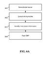
- FIG. 6A is a flow diagram illustrating a method for reducing error propagation during processing of a received frame comprising variable symbol-modulation, the method including the following steps: In step 601 , demodulating the header of the received frame using a first predetermined slicing mode. In step 602 , extracting from the received header the proper slicing modes for slicing the frame's payload. In step 603 , based on the proper slicing modes, slicing at least some of the payload symbols using a second slicing mode. And in step 604 , feeding a DBF with the at least some of the payload symbols. Optionally, based on the proper slicing modes, slicing at least some of the remaining payload symbols using a third slicing mode. And optionally, having a feedback loop by feeding the slicer with the DBF output.
- FIG. 6B is a flow diagram illustrating a method for reducing error propagation during reception and processing of a received frame, the method including the following steps: In step 611 , receiving by a receiver a frame comprising symbols. In step 612 , slicing by a slicer a first portion of the symbols using a first predetermined slicing mode. In step 613 , extracting from the first portion of the symbols the proper slicing mode for a second portion of the frame payload comprising dynamically modulated symbols. In step 614 , processing the second portion symbols using the proper slicing mode. And in step 615 , feeding a DBF with the at least some of the payload symbols.
Landscapes
- Engineering & Computer Science (AREA)
- Signal Processing (AREA)
- Computer Networks & Wireless Communication (AREA)
- Power Engineering (AREA)
- Quality & Reliability (AREA)
- Detection And Prevention Of Errors In Transmission (AREA)
Abstract
Description
Claims (45)
Priority Applications (3)
| Application Number | Priority Date | Filing Date | Title |
|---|---|---|---|
| US12/910,807 US8930795B1 (en) | 2010-10-24 | 2010-10-24 | Methods for slicing dynamically modulated symbols |
| US14/536,654 US9210018B2 (en) | 2010-10-24 | 2014-11-09 | Slicer for dynamically modulated symbols |
| US14/536,656 US9294319B2 (en) | 2010-10-24 | 2014-11-09 | Receivers for dynamically modulated symbols |
Applications Claiming Priority (1)
| Application Number | Priority Date | Filing Date | Title |
|---|---|---|---|
| US12/910,807 US8930795B1 (en) | 2010-10-24 | 2010-10-24 | Methods for slicing dynamically modulated symbols |
Related Child Applications (2)
| Application Number | Title | Priority Date | Filing Date |
|---|---|---|---|
| US14/536,656 Continuation US9294319B2 (en) | 2010-10-24 | 2014-11-09 | Receivers for dynamically modulated symbols |
| US14/536,654 Continuation US9210018B2 (en) | 2010-10-24 | 2014-11-09 | Slicer for dynamically modulated symbols |
Publications (1)
| Publication Number | Publication Date |
|---|---|
| US8930795B1 true US8930795B1 (en) | 2015-01-06 |
Family
ID=52117445
Family Applications (3)
| Application Number | Title | Priority Date | Filing Date |
|---|---|---|---|
| US12/910,807 Active 2032-10-09 US8930795B1 (en) | 2010-10-24 | 2010-10-24 | Methods for slicing dynamically modulated symbols |
| US14/536,654 Active US9210018B2 (en) | 2010-10-24 | 2014-11-09 | Slicer for dynamically modulated symbols |
| US14/536,656 Active US9294319B2 (en) | 2010-10-24 | 2014-11-09 | Receivers for dynamically modulated symbols |
Family Applications After (2)
| Application Number | Title | Priority Date | Filing Date |
|---|---|---|---|
| US14/536,654 Active US9210018B2 (en) | 2010-10-24 | 2014-11-09 | Slicer for dynamically modulated symbols |
| US14/536,656 Active US9294319B2 (en) | 2010-10-24 | 2014-11-09 | Receivers for dynamically modulated symbols |
Country Status (1)
| Country | Link |
|---|---|
| US (3) | US8930795B1 (en) |
Cited By (5)
| Publication number | Priority date | Publication date | Assignee | Title |
|---|---|---|---|---|
| US9559880B1 (en) * | 2016-03-04 | 2017-01-31 | Inphi Corporation | Eye modulation for pulse-amplitude modulation communication systems |
| EP3293931A1 (en) | 2015-01-25 | 2018-03-14 | Valens Semiconductor Ltd. | Transceiver and method for fast recovery from quality degradation |
| US10171182B2 (en) | 2015-01-25 | 2019-01-01 | Valens Semiconductor Ltd. | Sending known data to support fast convergence |
| EP3429113A1 (en) | 2016-01-25 | 2019-01-16 | Valens Semiconductor Ltd. | Fast recovery from differential interference using limited retransmission |
| US10256920B2 (en) | 2015-01-25 | 2019-04-09 | Valens Semiconductor Ltd. | Mode-conversion digital canceller for high bandwidth differential signaling |
Citations (14)
| Publication number | Priority date | Publication date | Assignee | Title |
|---|---|---|---|---|
| US5541964A (en) * | 1993-08-30 | 1996-07-30 | At&T Corp. | Distortion compensation technique |
| US5608755A (en) | 1994-10-14 | 1997-03-04 | Rakib; Selim | Method and apparatus for implementing carrierless amplitude/phase encoding in a network |
| US6269116B1 (en) | 1997-09-19 | 2001-07-31 | Telefonaktiebolaget Lm Ericsson (Publ) | Method and arrangement for demodulating data symbols |
| US20020057713A1 (en) | 2000-04-07 | 2002-05-16 | Bagchi Amit G. | Method for selecting frame encoding parameters to improve transmission performance in a frame-based communications network |
| US6463103B1 (en) * | 1998-01-16 | 2002-10-08 | Ess Technology, Inc. | Frame-based sign inversion method and system for spectral shaping for pulse-coded-modulation modems |
| US6570919B1 (en) | 1999-07-30 | 2003-05-27 | Agere Systems Inc. | Iterative decoding of data packets employing decision feedback equalization |
| US6697424B1 (en) | 2003-05-06 | 2004-02-24 | Industrial Technology Research Institute | Fast convergent pipelined adaptive decision feedback equalizer using post-cursor processing filter |
| US20050129107A1 (en) | 2002-04-17 | 2005-06-16 | Jeongsoon Park | Equalizer/foward error correction automatic mode selector |
| US6912208B2 (en) | 2002-11-07 | 2005-06-28 | Solarflare Communications, Inc. | Method and apparatus for equalization and crosstalk mitigation |
| US20050249275A1 (en) | 2004-05-04 | 2005-11-10 | Rdc Semiconductor Co., Ltd. | Timing recovery method and device for combining pre-filtering and feed-forward equalizing functions |
| US20070230554A1 (en) * | 2006-03-31 | 2007-10-04 | Ahmed Said | Effective adaptive filtering techniques |
| US20090110047A1 (en) | 2007-10-31 | 2009-04-30 | Agere Systems Inc. | Demodulator with configurable adaptive equalizer |
| US8023530B1 (en) * | 2009-01-07 | 2011-09-20 | L-3 Communications Corp. | Physical layer quality of service for wireless communications |
| US8027409B2 (en) * | 2007-12-21 | 2011-09-27 | Agere Systems Inc. | Noise prediction-based signal detection and cross-talk mitigation |
-
2010
- 2010-10-24 US US12/910,807 patent/US8930795B1/en active Active
-
2014
- 2014-11-09 US US14/536,654 patent/US9210018B2/en active Active
- 2014-11-09 US US14/536,656 patent/US9294319B2/en active Active
Patent Citations (14)
| Publication number | Priority date | Publication date | Assignee | Title |
|---|---|---|---|---|
| US5541964A (en) * | 1993-08-30 | 1996-07-30 | At&T Corp. | Distortion compensation technique |
| US5608755A (en) | 1994-10-14 | 1997-03-04 | Rakib; Selim | Method and apparatus for implementing carrierless amplitude/phase encoding in a network |
| US6269116B1 (en) | 1997-09-19 | 2001-07-31 | Telefonaktiebolaget Lm Ericsson (Publ) | Method and arrangement for demodulating data symbols |
| US6463103B1 (en) * | 1998-01-16 | 2002-10-08 | Ess Technology, Inc. | Frame-based sign inversion method and system for spectral shaping for pulse-coded-modulation modems |
| US6570919B1 (en) | 1999-07-30 | 2003-05-27 | Agere Systems Inc. | Iterative decoding of data packets employing decision feedback equalization |
| US20020057713A1 (en) | 2000-04-07 | 2002-05-16 | Bagchi Amit G. | Method for selecting frame encoding parameters to improve transmission performance in a frame-based communications network |
| US20050129107A1 (en) | 2002-04-17 | 2005-06-16 | Jeongsoon Park | Equalizer/foward error correction automatic mode selector |
| US6912208B2 (en) | 2002-11-07 | 2005-06-28 | Solarflare Communications, Inc. | Method and apparatus for equalization and crosstalk mitigation |
| US6697424B1 (en) | 2003-05-06 | 2004-02-24 | Industrial Technology Research Institute | Fast convergent pipelined adaptive decision feedback equalizer using post-cursor processing filter |
| US20050249275A1 (en) | 2004-05-04 | 2005-11-10 | Rdc Semiconductor Co., Ltd. | Timing recovery method and device for combining pre-filtering and feed-forward equalizing functions |
| US20070230554A1 (en) * | 2006-03-31 | 2007-10-04 | Ahmed Said | Effective adaptive filtering techniques |
| US20090110047A1 (en) | 2007-10-31 | 2009-04-30 | Agere Systems Inc. | Demodulator with configurable adaptive equalizer |
| US8027409B2 (en) * | 2007-12-21 | 2011-09-27 | Agere Systems Inc. | Noise prediction-based signal detection and cross-talk mitigation |
| US8023530B1 (en) * | 2009-01-07 | 2011-09-20 | L-3 Communications Corp. | Physical layer quality of service for wireless communications |
Cited By (11)
| Publication number | Priority date | Publication date | Assignee | Title |
|---|---|---|---|---|
| EP3293931A1 (en) | 2015-01-25 | 2018-03-14 | Valens Semiconductor Ltd. | Transceiver and method for fast recovery from quality degradation |
| EP3243307A4 (en) * | 2015-01-25 | 2018-03-21 | Valens Semiconductor Ltd. | Fast adaptive mode-conversion digital canceller |
| US10171182B2 (en) | 2015-01-25 | 2019-01-01 | Valens Semiconductor Ltd. | Sending known data to support fast convergence |
| US10225113B2 (en) | 2015-01-25 | 2019-03-05 | Valens Semiconductor Ltd. | Fast adaptive digital canceller |
| US10256920B2 (en) | 2015-01-25 | 2019-04-09 | Valens Semiconductor Ltd. | Mode-conversion digital canceller for high bandwidth differential signaling |
| US10270542B2 (en) | 2015-01-25 | 2019-04-23 | Valens Semiconductor Ltd. | Sending known data to support fast convergence |
| US10277336B2 (en) | 2015-01-25 | 2019-04-30 | Valens Semiconductor Ltd. | Fast recovery from interferences using limited retransmissions |
| US10523339B2 (en) | 2015-01-25 | 2019-12-31 | Valens Semiconductor Ltd. | Reducing transmission rate to support fast convergence |
| EP3429113A1 (en) | 2016-01-25 | 2019-01-16 | Valens Semiconductor Ltd. | Fast recovery from differential interference using limited retransmission |
| US9559880B1 (en) * | 2016-03-04 | 2017-01-31 | Inphi Corporation | Eye modulation for pulse-amplitude modulation communication systems |
| US9755870B1 (en) * | 2016-03-04 | 2017-09-05 | Inphi Corporation | Eye modulation for pulse-amplitude modulation communication systems |
Also Published As
| Publication number | Publication date |
|---|---|
| US20150063475A1 (en) | 2015-03-05 |
| US20150063474A1 (en) | 2015-03-05 |
| US9294319B2 (en) | 2016-03-22 |
| US9210018B2 (en) | 2015-12-08 |
Similar Documents
| Publication | Publication Date | Title |
|---|---|---|
| US9210018B2 (en) | Slicer for dynamically modulated symbols | |
| US8014442B2 (en) | Communicating data using wideband communications | |
| WO2014138636A1 (en) | Rate adaptation using raw bit error rate | |
| EP3293931B1 (en) | Transceiver and method for fast recovery from quality degradation | |
| CN101262431B (en) | Communication device and communication method | |
| US20160277127A1 (en) | Mode-conversion digital canceller for high bandwidth differential signaling | |
| EP3429113B1 (en) | Fast recovery from differential interference using limited retransmission | |
| US20040258168A1 (en) | Communicating data using wideband communications | |
| KR102262540B1 (en) | The encoder scheduling system for DVB-S2 multi-channel transmission | |
| US20160277067A1 (en) | Reducing transmission rate to support fast convergence | |
| US10270542B2 (en) | Sending known data to support fast convergence | |
| KR102211519B1 (en) | Apparatus for transmitting broadcast signals, apparatus for receiving broadcast signals, and method therefor | |
| US20080013648A1 (en) | Decoding system and method for deciding a compensated signal | |
| AU2002329917A1 (en) | Communicating data using wideband communications |
Legal Events
| Date | Code | Title | Description |
|---|---|---|---|
| AS | Assignment |
Owner name: VALENS SEMICONDUCTOR LTD., ISRAEL Free format text: ASSIGNMENT OF ASSIGNORS INTEREST;ASSIGNORS:LIDA, EYRAN;COHEN, GABY GUR;SALAMON, AVIV;REEL/FRAME:025184/0865 Effective date: 20101024 |
|
| AS | Assignment |
Owner name: BANK LEUMI LE-ISRAEL B.M., ISRAEL Free format text: SECOND AMENDMENT TO U.S. INTELLECTUAL PROPERTY SECUITY AGREEMENT;ASSIGNOR:VALENS SEMICONDUCTOR LTD.;REEL/FRAME:025927/0678 Effective date: 20110216 Owner name: KREOS CAPITAL II LIMITED, CHANNEL ISLANDS Free format text: SECOND AMENDMENT TO U.S. INTELLECTUAL PROPERTY SECUITY AGREEMENT;ASSIGNOR:VALENS SEMICONDUCTOR LTD.;REEL/FRAME:025927/0678 Effective date: 20110216 |
|
| AS | Assignment |
Owner name: VALENS SEMICONDUCTOR LTD, ISRAEL Free format text: RELEASE OF SECURITY AGREEMENT;ASSIGNOR:KREOS CAPITAL II LIMITED;REEL/FRAME:027167/0521 Effective date: 20110901 |
|
| STCF | Information on status: patent grant |
Free format text: PATENTED CASE |
|
| MAFP | Maintenance fee payment |
Free format text: PAYMENT OF MAINTENANCE FEE, 4TH YR, SMALL ENTITY (ORIGINAL EVENT CODE: M2551) Year of fee payment: 4 |
|
| MAFP | Maintenance fee payment |
Free format text: PAYMENT OF MAINTENANCE FEE, 8TH YR, SMALL ENTITY (ORIGINAL EVENT CODE: M2552); ENTITY STATUS OF PATENT OWNER: SMALL ENTITY Year of fee payment: 8 |