US8919378B2 - Compact electrically controlled four-way valve with port mixing - Google Patents
Compact electrically controlled four-way valve with port mixing Download PDFInfo
- Publication number
- US8919378B2 US8919378B2 US13/439,193 US201213439193A US8919378B2 US 8919378 B2 US8919378 B2 US 8919378B2 US 201213439193 A US201213439193 A US 201213439193A US 8919378 B2 US8919378 B2 US 8919378B2
- Authority
- US
- United States
- Prior art keywords
- core
- outlet port
- sidewall
- manifold
- valve
- Prior art date
- Legal status (The legal status is an assumption and is not a legal conclusion. Google has not performed a legal analysis and makes no representation as to the accuracy of the status listed.)
- Expired - Fee Related, expires
Links
Images


Classifications
-
- F—MECHANICAL ENGINEERING; LIGHTING; HEATING; WEAPONS; BLASTING
- F16—ENGINEERING ELEMENTS AND UNITS; GENERAL MEASURES FOR PRODUCING AND MAINTAINING EFFECTIVE FUNCTIONING OF MACHINES OR INSTALLATIONS; THERMAL INSULATION IN GENERAL
- F16K—VALVES; TAPS; COCKS; ACTUATING-FLOATS; DEVICES FOR VENTING OR AERATING
- F16K11/00—Multiple-way valves, e.g. mixing valves; Pipe fittings incorporating such valves
- F16K11/02—Multiple-way valves, e.g. mixing valves; Pipe fittings incorporating such valves with all movable sealing faces moving as one unit
- F16K11/08—Multiple-way valves, e.g. mixing valves; Pipe fittings incorporating such valves with all movable sealing faces moving as one unit comprising only taps or cocks
- F16K11/085—Multiple-way valves, e.g. mixing valves; Pipe fittings incorporating such valves with all movable sealing faces moving as one unit comprising only taps or cocks with cylindrical plug
- F16K11/0856—Multiple-way valves, e.g. mixing valves; Pipe fittings incorporating such valves with all movable sealing faces moving as one unit comprising only taps or cocks with cylindrical plug having all the connecting conduits situated in more than one plane perpendicular to the axis of the plug
-
- Y—GENERAL TAGGING OF NEW TECHNOLOGICAL DEVELOPMENTS; GENERAL TAGGING OF CROSS-SECTIONAL TECHNOLOGIES SPANNING OVER SEVERAL SECTIONS OF THE IPC; TECHNICAL SUBJECTS COVERED BY FORMER USPC CROSS-REFERENCE ART COLLECTIONS [XRACs] AND DIGESTS
- Y10—TECHNICAL SUBJECTS COVERED BY FORMER USPC
- Y10T—TECHNICAL SUBJECTS COVERED BY FORMER US CLASSIFICATION
- Y10T137/00—Fluid handling
- Y10T137/8593—Systems
- Y10T137/86493—Multi-way valve unit
- Y10T137/86863—Rotary valve unit
- Y10T137/86871—Plug
Definitions
- the present invention relates to fluid flow control valves and more particularly to a compact four-way fluid flow control valve, wherein the inlet and outlet ports are all disposed on a sidewall of the valve.
- Fluid flow control valve mechanisms utilize one or more fluid valve ports for the purpose of controlling flow of a fluid.
- a fluid flow control valve includes a first valve body having at least one port fluidically communicating with one or more fluid transfer lines for providing delivery and/or removal of fluid with respect to a fluid flow system, and further includes a second valve body, movable in relation to the first valve body, having one or more ports which are alignable with the one of more ports of the first valve body.
- fluid flow through the fluid flow control valve is regulated.
- the degree of alignment may be controlled by a motive device (i.e., a motor) which is electronically controlled.
- the present invention is a compact four-way fluid flow control valve wherein the inlet and outlet ports are all disposed on a manifold sidewall of the valve, and wherein provided are: prevention of cross-port leakage, a range of fluid port opening sizes, fluid flow mixing between selected ports, allowance for of manufacturing variation, and robustness with respect to debris present in the fluid.
- the compact four-way fluid flow control valve includes a hollow valve core defined by a cylindrically shaped core sidewall which is rotatively disposed within a hollow manifold defined by a cylindrically shaped manifold sidewall.
- a first valve plane and a second valve plane are both transversely disposed with respect to a longitudinal valve axis, wherein the first valve plane is offset with respect to the second valve plane along the longitudinal valve axis.
- the valve core has a drive stem at one longitudinal end thereof which passes out of the cylindrical manifold so as to be rotatively driven by an electrical drive system.
- the core sidewall has a first core opening formed therein which is preferably bisected by the first valve plane, and further has a second core opening formed therein which is preferably bisected by the second valve plane.
- Each of the first and second core openings has a respective predetermined circumferential location on the core sidewall, as well as a respective predetermined angular range of the circumference of the core sidewall, wherein the first core opening has an angular range much larger than that of the second core opening.
- the manifold has four ports formed in the manifold sidewall, namely: a first outlet port, a second outlet port, a third outlet port, and an inlet port.
- the inlet port and the first outlet port are preferably bisected by the first valve plane, and the second and third outlet ports are preferably bisected by the second valve plane.
- Each of the inlet port and the first outlet port have a first predetermined mutual angular separation of the circumference of the manifold sidewall, and each of the second and third outlet ports have a second predetermined mutual angular separation of the circumference of the manifold sidewall, wherein the first predetermined angular separation is much larger than the second predetermined angular separation.
- the valve core has first, second and third annular seals disposed at blind portions of the core wall which are interstitial with respect to the first and second core openings (that is, none of the annular seals is disposed in circumscribing relation to either of the core openings).
- the annular seals may be O-rings seated in the core wall or may be convex loops integrally formed of an overmold of the valve core.
- a fluid flow system is connected to each of the inlet port and the first, second and third outlet ports, wherein the fluid flow system may be for example a motor vehicle coolant system.
- An electric motor of an electrical drive system selectively rotates the valve core with respect to the manifold via electronic control responsive to sensed conditions of the fluid flow system.
- the first second and third annular seals are mutually disposed relative to the first and second core openings, and the first and second core openings and the first, second and third annular seals are disposed relative to the inlet port and the first, second and third outlet ports such that when the valve core is rotated with respect to the manifold, the inlet port can fluidically communicate exclusively with any one of the first, second and third outlet ports, and can mix fluid between the first and second outlet ports and between the second and third outlet ports.
- FIG. 1 is an exploded, isometric, front facing view of the compact four-way fluid flow control valve according to the present invention.
- FIG. 2 is an exploded, isometric, rear facing view of the compact four-way fluid flow control valve according to the present invention (the manifold cap being omitted).
- FIG. 3 is an isometric, front facing view of the compact four-way fluid flow control valve according to the present invention, showing additionally a portion of an electrical drive system therefor.
- FIG. 4 is a schematic representation of the compact four-way fluid flow control valve operatively interfaced with a fluid flow control system.
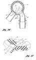
- FIG. 5 is an isometric view of the valve core of the compact four-way fluid flow control valve according to the present invention, showing annular seals in the from of O-rings disposed in grooves.
- FIG. 6 is a sectional view of the valve core of the compact four-way fluid flow control valve according to the present invention, seen along line 6 - 6 of FIG. 5 .
- FIG. 7 is a sectional view of the valve core of the compact four-way fluid flow control valve according to the present invention, seen along line 7 - 7 of FIG. 5 .
- FIG. 8 is an isometric view of the valve core of the compact four-way fluid flow control valve according to the present invention, showing annular seals which are integral of an overmold of the valve core.
- FIG. 9 is a sectional view of the valve core of the compact four-way fluid flow control valve according to the present invention, seen along line 9 - 9 of FIG. 8 .
- FIG. 10 is a sectional view of the valve core of the compact four-way fluid flow control valve according to the present invention, seen along line 10 - 10 of FIG. 8 .
- FIG. 11 is an isometric, front facing view of the manifold of the compact four-way fluid flow control valve according to the present invention.
- FIG. 12 is a sectional view of the manifold of the compact four-way fluid flow control valve according to the present invention, seen along line 12 - 12 of FIG. 11 .
- FIG. 13 is a sectional view of the manifold of the compact four-way fluid flow control valve according to the present invention, seen along line 13 - 13 of FIG. 11 .
- FIG. 14 is an isometric front facing view of the compact four-way fluid flow control valve according to the present invention.
- FIG. 15 is a sectional view of the compact four-way fluid flow control valve according to the present invention, seen along line 15 - 15 of FIG. 14 , wherein 100% of fluid flow to the first outlet port is provided.
- FIG. 16 is a sectional view of the compact four-way fluid flow control valve according to the present invention, seen along line 16 - 16 of FIG. 14 , wherein 100% of fluid flow to the first outlet port is provided.
- FIG. 17 is an isometric, front facing view of the compact four-way fluid flow control valve according to the present invention.
- FIG. 18 is a sectional view of the compact four-way fluid flow control valve according to the present invention, seen along line 18 - 18 of FIG. 17 , wherein 100% of fluid flow to the second outlet port is provided.
- FIG. 19 is a sectional view of the compact four-way fluid flow control valve according to the present invention, seen along line 19 - 19 of FIG. 17 , wherein 100% of fluid flow to the second outlet port is provided.
- FIG. 20 is an isometric, front facing view of the compact four-way fluid flow control valve according to the present invention.
- FIG. 21 is a sectional view of the compact four-way fluid flow control valve according to the present invention, seen along line 21 - 21 of FIG. 20 , wherein 100% of fluid flow to the third outlet port is provided.
- FIG. 22 is a sectional view of the compact four-way fluid flow control valve according to the present invention, seen along line 22 - 22 of FIG. 20 , wherein 100% of fluid flow to the third outlet port is provided.
- FIG. 23 is an isometric, front facing view of the compact four-way fluid flow control valve according to the present invention.
- FIG. 24 is a sectional view of the compact four-way fluid flow control valve according to the present invention, seen along line 24 - 24 of FIG. 23 , wherein 50% of fluid flow to each of the second and third outlet ports is provided.
- FIG. 25 is a sectional view of the compact four-way fluid flow control valve according to the present invention, seen along line 25 - 25 of FIG. 23 , wherein 50% of fluid flow to each of the second and third outlet ports is provided.
- FIG. 26 is a sectional view of the compact four-way fluid flow control valve according to the present invention, showing a gap controlled fluid flow to the second outlet port.
- FIG. 27 is a detail sectional view of the compact four-way fluid flow control valve according to the present invention, seen at circle 27 of FIG. 26 .
- FIGS. 1 through 27 depict various aspects of a compact four-way fluid flow control valve according to the present invention.
- FIGS. 1 through 4 depicted is the compact four-way fluid flow control valve 100 in accordance with the present invention, which includes a valve core 102 rotatively disposed within a manifold 104 .
- a first valve plane 106 and a second valve plane 108 are both transversely disposed with respect to a longitudinal valve axis 110 , wherein the first valve plane is separated with respect to the second valve plane by a planes separation 112 parallel to the longitudinal valve axis, the planes separation being less than the longitudinal height 114 of the manifold.
- the valve core 102 has a hollow interior space 116 defined by a cylindrically shaped core sidewall 118 .
- the manifold has a hollow interior space 120 , whereat is rotatively disposed the valve core 102 , defined by a cylindrically shaped manifold sidewall 122 .
- the valve core 102 has a drive stem 124 at a longitudinal end 126 which passes out of the manifold 104 so as to be rotatively driven by an electric motor 130 of an electrical drive system 132 , by way of example as that schematically shown at FIG. 4 .
- the electric motor 130 has a housing 136 which is sealingly interfaced with the lower longitudinal end 138 of the manifold 104 , and the upper longitudinal end 128 of the manifold via a manifold cap 134 , which by way of example (as shown) may be threadingly engaged with the manifold sidewall 122 .
- the electric motor 130 rotates the valve core 102 clockwise or counterclockwise with respect to the manifold 104 by command of an electronic controller 140 responsive to its programming and the sensed condition of a fluid flow system 142 via data from various sensors 144 .
- the fluid flow system 142 may be a coolant system of a motor vehicle.
- the core sidewall 118 has a first core opening 150 formed therein which is preferably bisected by the first valve plane 106 , and further has a second core opening 152 formed therein which is preferably bisected by the second valve plane 108 .
- Each of the first and second core openings 150 , 152 has a respective predetermined circumferential location of the core sidewall, comparatively indicated with respect to FIGS. 6 and 7 , in which a center arc point 154 of the first core opening is circumferentially displaced from the center arc point 156 of the second core opening, by of example one hundred twenty degrees.
- each of the first and second core openings 150 , 152 has a respective predetermined angular range of the circumference of the core sidewall 118 , wherein the first core opening has an angular range much larger than that of the second core opening.
- the first core opening 150 may have an angular range 146 of about 204 degrees of arc
- the second core opening 152 may have an angular range 148 of about seventy degrees of arc.
- the manifold 104 has four ports formed in the manifold sidewall 122 , namely: an inlet port 160 , a first outlet port 162 , a second outlet port 164 , and a third outlet port 166 .
- the inlet port 160 and the first outlet port 162 are preferably bisected by the first valve plane 106
- the second and third outlet ports 154 , 156 are preferably bisected by the second valve plane 108 .
- the inlet port 160 may have an angular range 250 of about thirty three degrees of arc
- the first outlet port 162 may have an angular range 252 of about thirty three degrees of arc
- the second outlet port 164 may have an angular range 254 of about thirty three degrees of arc
- the third outlet port 166 may have an angular range 256 of about thirty three degrees of arc.
- Each of the inlet port and the first, second and third outlet ports are preferably circular, but other shapes are possible.
- Each of the inlet port 160 and the first outlet port 162 have a first predetermined mutual minimal circumferential displacement at the manifold sidewall 122
- each of the second and third outlet ports 164 , 166 have a second predetermined mutual minimal circumferential displacement at the manifold sidewall, wherein the first predetermined mutual minimal circumferential displacement is much larger than the second predetermined mutual minimal circumferential displacement.
- the inlet port 160 may have a first predetermined mutual minimal circumferential displacement 220 with respect to the first outlet port 162 of about one hundred sixteen degrees of arc, and may have a first predetermined mutual maximal circumferential displacement 222 with respect to the first outlet port of about one hundred seventy six degrees of arc; and the second outlet port may have a second predetermined mutual minimal circumferential displacement 224 with respect to the third outlet port 164 of about thirty two degrees of arc, and may have a second predetermined mutual maximal circumferential displacement 226 with respect to the third outlet port of about two hundred sixty degrees of arc.
- the valve core 102 has a first annular seal 170 which is preferably bisected by the first plane 106 , and further has second and third annular seals 172 , 174 which are preferably bisected by the second plane 108 .
- Each of the first, second and third annular seals 170 , 172 , 174 are disposed on the core sidewall 118 in abutting relation to the manifold sidewall 122 (see for example FIGS.
- first annular seal 170 may have an angular range 240 of about one hundred thirty four degrees of arc
- the second annular seal 172 may have an angular range 242 of about one hundred thirty degrees of arc
- the third annular seal 174 may have an angular range 244 of about sixty six degrees of arc.
- the first, second and third annular seals 170 , 172 , 174 may be in the form of O-rings 180 seated in slots 182 of the core sidewall, wherein the techniques for retaining the O-rings as described in U.S. patent application Ser. No. 13/118,751, filed on May 31, 2011 to applicants B. Bartnick, P. Valencia, Jr., C. Johnson and B. Tompkins and assigned to the assignee hereof, entitled “Fluid Valve Port Optimized for Robustness with Standard O-Ring Seal”, the disclosure of which is hereby incorporated herein by reference.
- the first, second and third annular seals 170 , 172 , 174 may be convex loops 182 integrally formed of an overmold 184 of the core sidewall 1181 of the valve core 1021 , wherein, by way of example the valve core may be composed of aluminum and the overmold of EPDM (ethylene propylene diene monomer M class rubber).
- EPDM ethylene propylene diene monomer M class rubber
- the first second and third annular seals are mutually disposed relative to the first and second core openings, and the first and second core openings and the first, second and third annular seals are disposed relative to the inlet port and the first, second and third outlet ports such that when the valve core is rotated with respect to the manifold, the inlet port can fluidically communicate exclusively with any one of the first, second and third outlet ports, and can mix fluid between the first and second outlet ports and between the second and third outlet ports.
- the longitudinal diameter 210 of the first core opening 150 exceeds the diameter 218 of the inlet port 160 , and similarly as well, that of the diameters of the first, second and third outlet ports 162 , 164 , 166 ;
- the first, second and third annular seals 170 , 172 , 174 have a longitudinal diameter 212 at least as large as that of the first and second core openings (see for example the port cross-sections at FIGS. 15 and 16 );
- the first and second core openings are longitudinally spaced apart by a length 214 that is at least as large as the length 216 of longitudinal spacing between the first annular seal with respect to the second and third annular seals.
- the first annular seal 170 may have an angular range 240 of about one hundred thirty four degrees of arc; the second annular seal 172 may have an angular range 242 of about one hundred thirty degrees of arc; and the third annular seal 174 may have an angular range 244 of about sixty six degrees of arc.
- each of the inlet port 160 , and the first, second and third outlet ports 162 , 164 , 166 are shown provided with a respective external port fitting 190 , 192 , 194 , 196 for providing connection interface with a fluid flow system, as for example fluid flow system 142 of FIG. 4 , via fluid lines 200 , 202 , 204 , 206 , and wherein, as described with respect to FIGS. 3 and 4 , an electric motor 130 of the electrical drive system 132 selectively rotates the valve core with respect to the manifold via electronic control responsive to sensed conditions of the fluid flow system.
- the fluid flow is precisely controlled from the inlet port to any of the first, second and third outlet ports.
- FIGS. 14 through 16 depicted is a scenario in which 100% of fluid flow passes through the first outlet port 162 .
- the valve core 102 has been rotated with respect to the manifold 104 to the position 1 indicated at FIG. 15 , wherein the inlet port 160 and the first outlet port 162 are fully open to the first core opening 150 .
- the valve core sidewall 118 with the aid of the second annular seal 172 has effectively closed the second and third outlet ports 164 , 166 to fluid flow.
- FIGS. 17 through 19 depicted is a scenario in which 100% of fluid flow passes through the second outlet port 164 .
- the valve core 102 has been rotated with respect to the manifold 104 counterclockwise from the angular position 1 indicated at FIG. 15 to the angular position 2 indicated at FIG. 18 , wherein the inlet port 160 is fully open to the first core opening 150 , while the first outlet port 162 is closed to fluid flow via the core sidewall 118 aided by the first annular seal 170 having effectively closed all fluid flow at the first outlet port 160 .
- valve core sidewall with the aid of the second annular seal 172 has effectively closed all fluid flow at the third outlet port 166 , while the second outlet port 164 is fully open to second core opening 152 , whereby fluid flows from the inlet port into the first core opening, out the second core opening and into the second outlet port.
- FIGS. 20 through 22 depicted is a scenario in which 100% of fluid flow passes through the third outlet port 166 .
- the valve core 102 has been rotated with respect to the manifold 104 counterclockwise from the angular position 2 indicated at FIG. 18 to the angular position 3 indicated at FIG. 21 , wherein the inlet port 160 is fully open to the first core opening 150 , while the first outlet port 162 is closed to fluid flow via the core sidewall 118 aided by the first annular seal 170 having effectively closed all fluid flow at the first outlet port 160 .
- valve core sidewall with the aid of the third annular seal 174 has effectively closed all fluid flow at the second outlet port 164 , while the third outlet port 166 is fully open to second core opening 152 , whereby fluid flows from the inlet port into the first core opening, out the second core opening and into the third outlet port.
- FIGS. 23 through 25 depicted is a scenario in which 50% of fluid flow passes through each of the second and third outlet ports 164 , 166 .
- the valve core 102 has been rotated with respect to the manifold 104 to the angular position as indicated in FIGS. 24 and 25 , intermediate between that of FIGS. 18 and 21 , wherein the inlet port 160 is fully open to the first core opening 150 , while the first outlet port 162 is closed to fluid flow via the core sidewall 118 aided by the first annular seal 170 .
- valve core sidewall 118 with the aid of the third annular seal 174 occludes 50% of the second outlet port 164 while the other 50% thereof is open to fluid flow via the second core opening 152
- valve core sidewall with the aid of the second annular seal 172 occludes 50% of the third outlet port 166 while the other 50% thereof is open to fluid flow via the second core opening 152 , whereby fluid flows from the inlet port into the first core opening, out the second core opening and equally into each of the second and third outlet ports.
- the first annular seal 170 has a first annular set back 220 from either side of the first core opening 150
- the second annular seal 172 has a second annular set back 222 from one side of the second core opening 152
- the third annular seal 174 has a third annular set back 224 from the other side of the second core opening.
- the first, second and third angular set backs 220 , 222 , 224 may have a respective angular range, additionally inclusive of one-half the diameter of the respective annular seals, 226 , 228 , 230 of about 10 degrees of arc.
- an interstitial opening 232 at any of the first second and third outlet ports.
- An interstitial opening 232 occurs when the valve core is angularly positioned with respect to the manifold such that the core sidewall is in occluding relation thereto and one of the first, second and third annular seals has a portion thereof which is fully exposed in the respective one of the first, second and third outlet ports.
- the interstitial opening 232 provides trickle fluid flow into the selected one of the first, second and third outlet ports.
- the third angular set back 224 of the third the annular seal 174 allows fluid to trickle through the interstitial opening 232 into the second outlet port 164 , while the third fluid port 166 is fully open.
- the above described preferred embodiment may be subject to change or modification.
- the fluid flow control valve may be configured such that the manifold has the inlet port and the first outlet port, the valve core has the first core opening, and the first annular seal is disposed on the first blind portion of the core sidewall.
Landscapes
- Engineering & Computer Science (AREA)
- General Engineering & Computer Science (AREA)
- Mechanical Engineering (AREA)
- Multiple-Way Valves (AREA)
- Sliding Valves (AREA)
Abstract
Description
| TABLE I | |||||
| Inlet | 1st |
2nd |
3rd Outlet | ||
| Ang. Pos. | Flow | Flow | Flow | Flow | |
| 1 | 100% | 100% | none | none | |
| bet. 1 and 2 | 100% | prop. mixing | prop. mixing | |
|
| 2 | 100 | none | 100% | none | |
| bet. 2 and 3 | 100% | none | prop. mixing | prop. mixing | |
| 3 | 100 | none | none | 100% | |
Claims (18)
Priority Applications (3)
| Application Number | Priority Date | Filing Date | Title |
|---|---|---|---|
| US13/439,193 US8919378B2 (en) | 2012-04-04 | 2012-04-04 | Compact electrically controlled four-way valve with port mixing |
| DE201310205430 DE102013205430A1 (en) | 2012-04-04 | 2013-03-27 | Compact electronically controlled four-way valve with connection mix |
| CN201310114707.0A CN103363155B (en) | 2012-04-04 | 2013-04-03 | The compact electronic with port hybrid controls cross valve |
Applications Claiming Priority (1)
| Application Number | Priority Date | Filing Date | Title |
|---|---|---|---|
| US13/439,193 US8919378B2 (en) | 2012-04-04 | 2012-04-04 | Compact electrically controlled four-way valve with port mixing |
Publications (2)
| Publication Number | Publication Date |
|---|---|
| US20130263949A1 US20130263949A1 (en) | 2013-10-10 |
| US8919378B2 true US8919378B2 (en) | 2014-12-30 |
Family
ID=49210078
Family Applications (1)
| Application Number | Title | Priority Date | Filing Date |
|---|---|---|---|
| US13/439,193 Expired - Fee Related US8919378B2 (en) | 2012-04-04 | 2012-04-04 | Compact electrically controlled four-way valve with port mixing |
Country Status (3)
| Country | Link |
|---|---|
| US (1) | US8919378B2 (en) |
| CN (1) | CN103363155B (en) |
| DE (1) | DE102013205430A1 (en) |
Cited By (7)
| Publication number | Priority date | Publication date | Assignee | Title |
|---|---|---|---|---|
| US20170089482A1 (en) * | 2015-09-24 | 2017-03-30 | Mahle International Gmbh | Electrically actuated valve |
| US20170363220A1 (en) * | 2016-06-15 | 2017-12-21 | Woco Industrietechnik Gmbh | Multiway control valve having a sealing carrier |
| US11221077B2 (en) | 2020-03-25 | 2022-01-11 | Hyundai Motor Company | Flow control valve apparatus |
| US11319863B2 (en) * | 2020-01-31 | 2022-05-03 | Hyundai Motor Company | Flow control valve apparatus |
| US20220252163A1 (en) * | 2021-02-05 | 2022-08-11 | Fox Factory, Inc. | Rotary flow control valve that requires no linear motion |
| US20220364653A1 (en) * | 2019-10-14 | 2022-11-17 | Vitesco Technologies GmbH | Fluid Valve |
| EP4051936A4 (en) * | 2019-10-30 | 2024-04-10 | Robertshaw Controls Company | Multi-port valve with partial circumferential seal arrangement |
Families Citing this family (24)
| Publication number | Priority date | Publication date | Assignee | Title |
|---|---|---|---|---|
| KR101500391B1 (en) * | 2013-12-20 | 2015-03-09 | 현대자동차 주식회사 | Engine having multi flow rate control valve |
| US10533485B2 (en) * | 2014-01-13 | 2020-01-14 | Coldfire, Inc. | Control valve |
| KR101575338B1 (en) * | 2014-07-08 | 2015-12-07 | 현대자동차 주식회사 | Coolant control valve of engine |
| CN104791522B (en) * | 2015-04-15 | 2017-05-10 | 华中科技大学 | Oil-way switching device |
| WO2016182536A1 (en) * | 2015-05-08 | 2016-11-17 | Volvo Truck Corporation | Three-way valve |
| ITUB20161092A1 (en) * | 2016-02-26 | 2017-08-26 | Bonomi Ind S R L | Ball valve and manufacturing method |
| US10465803B2 (en) | 2016-10-05 | 2019-11-05 | Johnson Controls Technology Company | Multipurpose valve assembly tool |
| JP6846907B2 (en) * | 2016-10-27 | 2021-03-24 | 株式会社山田製作所 | Control valve |
| CN108119672B (en) * | 2016-11-29 | 2020-05-19 | 杭州三花研究院有限公司 | Flow rate control device |
| WO2018099359A1 (en) | 2016-11-29 | 2018-06-07 | 杭州三花研究院有限公司 | Flow control device |
| JP7114890B2 (en) * | 2017-12-12 | 2022-08-09 | 株式会社デンソー | Cooling water control valve device |
| RU2669885C1 (en) * | 2017-09-01 | 2018-10-16 | Акционерное общество "Корпорация "Московский институт теплотехники" (АО "Корпорация "МИТ") | Gas flow rate controller |
| US11255450B2 (en) | 2018-12-19 | 2022-02-22 | Robertshaw Controls Company | Multi-port multi-plane valve |
| CN109595360B (en) * | 2018-12-21 | 2025-01-07 | 厦门松霖科技股份有限公司 | Water channel switching device and water outlet device |
| JP7400614B2 (en) * | 2020-04-28 | 2023-12-19 | 株式会社デンソー | valve device |
| JP2023528401A (en) * | 2020-05-29 | 2023-07-04 | レガシー ユーエス インコーポレイテッド | Fluid mixing devices such as ventilators |
| US11773990B2 (en) | 2020-06-05 | 2023-10-03 | Robertshaw Controls Company | Multi-port multi-mode valve |
| US11560952B2 (en) * | 2020-09-01 | 2023-01-24 | Hanon Systems | Variable cylinder wall for seals on plug valve |
| CN112212033B (en) * | 2020-09-07 | 2021-07-13 | 东风汽车集团有限公司 | A four-way valve and its control method |
| CN115218004B (en) * | 2021-04-16 | 2026-04-03 | 浙江三花汽车零部件有限公司 | control valve |
| DE102021110942A1 (en) * | 2021-04-28 | 2022-11-03 | HELLA GmbH & Co. KGaA | Fluid system valve and vehicle fluid system |
| DE102021110941A1 (en) * | 2021-04-28 | 2022-11-03 | HELLA GmbH & Co. KGaA | Valve and liquid tank for a liquid system, and liquid system for a vehicle |
| EP4155589B1 (en) * | 2021-09-24 | 2025-06-04 | Abb Schweiz Ag | Hydraulic valve for connecting two transverse pipes |
| US11703135B2 (en) * | 2021-12-03 | 2023-07-18 | Vitesco Technologies USA, LLC | Multi-port coolant flow control valve assembly |
Citations (26)
| Publication number | Priority date | Publication date | Assignee | Title |
|---|---|---|---|---|
| US1122848A (en) | 1913-12-26 | 1914-12-29 | Edgar J Bloom | Mixing-valve. |
| US2051278A (en) | 1930-02-24 | 1936-08-18 | Ernest J Svenson | Valve construction |
| US2547116A (en) | 1946-01-22 | 1951-04-03 | Mueller Co | Valve |
| US2578396A (en) | 1945-10-12 | 1951-12-11 | Dole Valve Co | Valve and sealing structure therefor |
| US3133723A (en) * | 1962-09-27 | 1964-05-19 | Walworth Co | Gas valves |
| US3991975A (en) * | 1975-07-08 | 1976-11-16 | Mueller Co. | Rotary plug valve with notched sealing ring groove |
| US3993099A (en) * | 1974-06-25 | 1976-11-23 | Imperial Chemical Industries Limited | Plug valves |
| USRE30224E (en) * | 1973-11-08 | 1980-03-11 | Purex Corporation | Valve construction |
| US4262880A (en) * | 1979-06-29 | 1981-04-21 | Nupro Company | Plug valve |
| US4540025A (en) | 1983-03-28 | 1985-09-10 | Grove Valve And Regulator Company | Throttling ball valve |
| US4890817A (en) | 1987-05-15 | 1990-01-02 | Plasson Maagan Michael Industries, Ltd. | Quarter-turn valve |
| US4958802A (en) * | 1988-04-07 | 1990-09-25 | United States Brass Corporation | Stop valve |
| US5037067A (en) * | 1990-10-29 | 1991-08-06 | Artek Industries, Inc. | High pressure rotary plug valve |
| US5113909A (en) | 1988-01-04 | 1992-05-19 | Neles Oy | Closing member for a valve |
| US5152321A (en) * | 1991-10-07 | 1992-10-06 | Ecowater Systems, Inc. | Bypass valve |
| US5188144A (en) * | 1991-08-29 | 1993-02-23 | Hoke Incorporated | Plug valve |
| US5234193A (en) * | 1992-02-03 | 1993-08-10 | Parker-Hannifin Corporation | Rotary plug valve with seat seal |
| US5511584A (en) | 1992-09-22 | 1996-04-30 | Leinen; Chris M. | Low noise rotary control valve |
| US5680889A (en) | 1996-09-23 | 1997-10-28 | Dresser Industries, Inc. | Low noise ball valve assembly |
| US5771929A (en) | 1996-10-24 | 1998-06-30 | Dresser Industries, Inc. | Low noise ball valve assembly with airfoil insert |
| US5906297A (en) | 1996-11-21 | 1999-05-25 | Cole; Russell H. | Multi-outlet depositor |
| US5931196A (en) * | 1998-04-29 | 1999-08-03 | United States Filter Corporation | Bypass valve |
| US6575195B2 (en) * | 2000-06-16 | 2003-06-10 | United States Filter Corporation | Bypass valve |
| US6874759B2 (en) | 2002-11-13 | 2005-04-05 | Smc Kabushiki Kaisha | Plug valve |
| US7044436B2 (en) | 2003-04-30 | 2006-05-16 | Pibiviesse S.P.A. | Regulation valve |
| US20060137536A1 (en) | 2003-01-20 | 2006-06-29 | De Jong Engineering Elburg B.V. | Dividing device |
Family Cites Families (4)
| Publication number | Priority date | Publication date | Assignee | Title |
|---|---|---|---|---|
| GB1230719A (en) * | 1969-11-14 | 1971-05-05 | ||
| JP2003021246A (en) * | 2001-07-06 | 2003-01-24 | Sekisui Chem Co Ltd | Mixing valve |
| FR2844571B1 (en) * | 2002-09-18 | 2008-02-29 | Valeo Thermique Moteur Sa | CONTROL VALVE FOR A FLUID CIRCUIT AND CIRCUIT COMPRISING SAID VALVE |
| US6994316B2 (en) * | 2003-01-16 | 2006-02-07 | General Electric Company | Rotor valve and seal |
-
2012
- 2012-04-04 US US13/439,193 patent/US8919378B2/en not_active Expired - Fee Related
-
2013
- 2013-03-27 DE DE201310205430 patent/DE102013205430A1/en not_active Withdrawn
- 2013-04-03 CN CN201310114707.0A patent/CN103363155B/en not_active Expired - Fee Related
Patent Citations (27)
| Publication number | Priority date | Publication date | Assignee | Title |
|---|---|---|---|---|
| US1122848A (en) | 1913-12-26 | 1914-12-29 | Edgar J Bloom | Mixing-valve. |
| US2051278A (en) | 1930-02-24 | 1936-08-18 | Ernest J Svenson | Valve construction |
| US2578396A (en) | 1945-10-12 | 1951-12-11 | Dole Valve Co | Valve and sealing structure therefor |
| US2547116A (en) | 1946-01-22 | 1951-04-03 | Mueller Co | Valve |
| US3133723A (en) * | 1962-09-27 | 1964-05-19 | Walworth Co | Gas valves |
| USRE30224E (en) * | 1973-11-08 | 1980-03-11 | Purex Corporation | Valve construction |
| US3993099A (en) * | 1974-06-25 | 1976-11-23 | Imperial Chemical Industries Limited | Plug valves |
| US3991975A (en) * | 1975-07-08 | 1976-11-16 | Mueller Co. | Rotary plug valve with notched sealing ring groove |
| US4262880A (en) * | 1979-06-29 | 1981-04-21 | Nupro Company | Plug valve |
| US4540025A (en) | 1983-03-28 | 1985-09-10 | Grove Valve And Regulator Company | Throttling ball valve |
| US4890817A (en) | 1987-05-15 | 1990-01-02 | Plasson Maagan Michael Industries, Ltd. | Quarter-turn valve |
| US5113909A (en) | 1988-01-04 | 1992-05-19 | Neles Oy | Closing member for a valve |
| US4958802A (en) * | 1988-04-07 | 1990-09-25 | United States Brass Corporation | Stop valve |
| US5037067A (en) * | 1990-10-29 | 1991-08-06 | Artek Industries, Inc. | High pressure rotary plug valve |
| US5188144A (en) * | 1991-08-29 | 1993-02-23 | Hoke Incorporated | Plug valve |
| US5327929A (en) * | 1991-08-29 | 1994-07-12 | Hoke Incorporated | Plug valve |
| US5152321A (en) * | 1991-10-07 | 1992-10-06 | Ecowater Systems, Inc. | Bypass valve |
| US5234193A (en) * | 1992-02-03 | 1993-08-10 | Parker-Hannifin Corporation | Rotary plug valve with seat seal |
| US5511584A (en) | 1992-09-22 | 1996-04-30 | Leinen; Chris M. | Low noise rotary control valve |
| US5680889A (en) | 1996-09-23 | 1997-10-28 | Dresser Industries, Inc. | Low noise ball valve assembly |
| US5771929A (en) | 1996-10-24 | 1998-06-30 | Dresser Industries, Inc. | Low noise ball valve assembly with airfoil insert |
| US5906297A (en) | 1996-11-21 | 1999-05-25 | Cole; Russell H. | Multi-outlet depositor |
| US5931196A (en) * | 1998-04-29 | 1999-08-03 | United States Filter Corporation | Bypass valve |
| US6575195B2 (en) * | 2000-06-16 | 2003-06-10 | United States Filter Corporation | Bypass valve |
| US6874759B2 (en) | 2002-11-13 | 2005-04-05 | Smc Kabushiki Kaisha | Plug valve |
| US20060137536A1 (en) | 2003-01-20 | 2006-06-29 | De Jong Engineering Elburg B.V. | Dividing device |
| US7044436B2 (en) | 2003-04-30 | 2006-05-16 | Pibiviesse S.P.A. | Regulation valve |
Non-Patent Citations (7)
| Title |
|---|
| Faucet Valve Insert having diagonally disposed O-ring and channel therefor of Moen Incorporated, North Olmstead, OH 44070. Believed on the market at least since 1990. |
| Generic Prior Art O-Rings and Channels Therefor. Known since at least before 2010. |
| Generic variable flow control valve, believed in use at least since 2010. |
| U.S. Appl. No. 13/118,751, filed May 31, 2011; inventors: Brian K. Bartnick, Pablo Valencia, Jr., Corry W. Johnson, and Bill F. Tompkins. |
| U.S. Appl. No. 13/216,631, filed Aug. 24, 2011; inventors: Brian K. Bartnick and Corry W. Johnson. |
| U.S. Appl. No. 13/413,079, filed Mar. 6, 2011; inventors: Pablo Valencia, Jr. and Brian K. Bartnick. |
| U.S. Appl. No. 13/439,193, filed Apr. 4, 2012; inventors: Brian K. Bartnick and Jr., Corry W. Johnson. |
Cited By (10)
| Publication number | Priority date | Publication date | Assignee | Title |
|---|---|---|---|---|
| US20170089482A1 (en) * | 2015-09-24 | 2017-03-30 | Mahle International Gmbh | Electrically actuated valve |
| US10203044B2 (en) * | 2015-09-24 | 2019-02-12 | Mahle International Gmbh | Electrically actuated valve |
| US20170363220A1 (en) * | 2016-06-15 | 2017-12-21 | Woco Industrietechnik Gmbh | Multiway control valve having a sealing carrier |
| US20220364653A1 (en) * | 2019-10-14 | 2022-11-17 | Vitesco Technologies GmbH | Fluid Valve |
| US12222041B2 (en) * | 2019-10-14 | 2025-02-11 | Vitesco Technologies GmbH | Fluid valve |
| EP4051936A4 (en) * | 2019-10-30 | 2024-04-10 | Robertshaw Controls Company | Multi-port valve with partial circumferential seal arrangement |
| US11319863B2 (en) * | 2020-01-31 | 2022-05-03 | Hyundai Motor Company | Flow control valve apparatus |
| US11221077B2 (en) | 2020-03-25 | 2022-01-11 | Hyundai Motor Company | Flow control valve apparatus |
| US20220252163A1 (en) * | 2021-02-05 | 2022-08-11 | Fox Factory, Inc. | Rotary flow control valve that requires no linear motion |
| US12410868B2 (en) * | 2021-02-05 | 2025-09-09 | Fox Factory, Inc. | Rotary flow control valve that requires no linear motion |
Also Published As
| Publication number | Publication date |
|---|---|
| US20130263949A1 (en) | 2013-10-10 |
| CN103363155A (en) | 2013-10-23 |
| DE102013205430A1 (en) | 2013-10-10 |
| CN103363155B (en) | 2016-06-08 |
Similar Documents
| Publication | Publication Date | Title |
|---|---|---|
| US8919378B2 (en) | Compact electrically controlled four-way valve with port mixing | |
| US20070044856A1 (en) | Diverter valve for water systems | |
| US8375977B2 (en) | Ball valve with single access port | |
| EP2075496B1 (en) | Fluid manifold for a heating and/or cooling system | |
| US20120060952A1 (en) | Volume booster with discrete capacity adjustment | |
| CN106461143B (en) | Swivel joint with hydraulic position signal | |
| CN203926909U (en) | Six mouthfuls of four way ball valves | |
| EP2696115B1 (en) | Three-position valve for water supply systems | |
| US9377127B2 (en) | Ball valve with square bore and quarter turn component | |
| CN221097568U (en) | Multi-way valve | |
| US20160091109A1 (en) | Low torque multi-circuit control valve | |
| EP2565502A1 (en) | Tap for water supply pipes | |
| CN203743507U (en) | Four-way filter ball valve | |
| US20160369908A1 (en) | Ball Valve Assembly | |
| US20130228247A1 (en) | Canted, single vane, three-way butterfly valve | |
| KR101321564B1 (en) | Wheel valve | |
| CN205477819U (en) | Filter cover with be used for installing valve of straining in filter cover | |
| EP2157342A1 (en) | A device for opening and closing outlets of a fluid distributor valve | |
| KR101814684B1 (en) | Ventilating systems | |
| JPH01299373A (en) | Four way change-over valve | |
| US20070095410A1 (en) | High pressure metering valve | |
| US20160091098A1 (en) | Integrable Barrel Valve and Irrigation Piping Component Comprising Same | |
| CN208595260U (en) | A kind of two way cock formula valve | |
| CN205806570U (en) | Porous flow divider | |
| KR20140105323A (en) | Banjo-needle valve |
Legal Events
| Date | Code | Title | Description |
|---|---|---|---|
| AS | Assignment |
Owner name: GM GLOBAL TECHNOLOGY OPERATIONS LLC, MICHIGAN Free format text: ASSIGNMENT OF ASSIGNORS INTEREST;ASSIGNORS:BARTNICK, BRIAN K.;JOHNSON, CORRY W.;REEL/FRAME:027987/0872 Effective date: 20120330 |
|
| AS | Assignment |
Owner name: WILMINGTON TRUST COMPANY, DELAWARE Free format text: SECURITY AGREEMENT;ASSIGNOR:GM GLOBAL TECHNOLOGY OPERATIONS LLC;REEL/FRAME:030694/0500 Effective date: 20101027 |
|
| AS | Assignment |
Owner name: GM GLOBAL TECHNOLOGY OPERATIONS LLC, MICHIGAN Free format text: RELEASE BY SECURED PARTY;ASSIGNOR:WILMINGTON TRUST COMPANY;REEL/FRAME:034287/0415 Effective date: 20141017 |
|
| STCF | Information on status: patent grant |
Free format text: PATENTED CASE |
|
| MAFP | Maintenance fee payment |
Free format text: PAYMENT OF MAINTENANCE FEE, 4TH YEAR, LARGE ENTITY (ORIGINAL EVENT CODE: M1551) Year of fee payment: 4 |
|
| FEPP | Fee payment procedure |
Free format text: MAINTENANCE FEE REMINDER MAILED (ORIGINAL EVENT CODE: REM.); ENTITY STATUS OF PATENT OWNER: LARGE ENTITY |
|
| LAPS | Lapse for failure to pay maintenance fees |
Free format text: PATENT EXPIRED FOR FAILURE TO PAY MAINTENANCE FEES (ORIGINAL EVENT CODE: EXP.); ENTITY STATUS OF PATENT OWNER: LARGE ENTITY |
|
| STCH | Information on status: patent discontinuation |
Free format text: PATENT EXPIRED DUE TO NONPAYMENT OF MAINTENANCE FEES UNDER 37 CFR 1.362 |
|
| FP | Lapsed due to failure to pay maintenance fee |
Effective date: 20221230 |