US8911103B2 - Adjustable portable light - Google Patents
Adjustable portable light Download PDFInfo
- Publication number
- US8911103B2 US8911103B2 US13/737,403 US201313737403A US8911103B2 US 8911103 B2 US8911103 B2 US 8911103B2 US 201313737403 A US201313737403 A US 201313737403A US 8911103 B2 US8911103 B2 US 8911103B2
- Authority
- US
- United States
- Prior art keywords
- clamp
- cylindrical housing
- portable light
- longitudinal axis
- engaging features
- Prior art date
- Legal status (The legal status is an assumption and is not a legal conclusion. Google has not performed a legal analysis and makes no representation as to the accuracy of the status listed.)
- Active
Links
- 238000000034 method Methods 0.000 claims description 11
- 238000005286 illumination Methods 0.000 description 6
- 230000008901 benefit Effects 0.000 description 3
- 210000003811 finger Anatomy 0.000 description 3
- 230000009471 action Effects 0.000 description 1
- 230000004913 activation Effects 0.000 description 1
- 238000010168 coupling process Methods 0.000 description 1
- 238000005859 coupling reaction Methods 0.000 description 1
- 230000003247 decreasing effect Effects 0.000 description 1
- 230000007246 mechanism Effects 0.000 description 1
- 230000004048 modification Effects 0.000 description 1
- 238000012986 modification Methods 0.000 description 1
- 238000005096 rolling process Methods 0.000 description 1
- 210000003813 thumb Anatomy 0.000 description 1
Images


Classifications
-
- B—PERFORMING OPERATIONS; TRANSPORTING
- B62—LAND VEHICLES FOR TRAVELLING OTHERWISE THAN ON RAILS
- B62J—CYCLE SADDLES OR SEATS; AUXILIARY DEVICES OR ACCESSORIES SPECIALLY ADAPTED TO CYCLES AND NOT OTHERWISE PROVIDED FOR, e.g. ARTICLE CARRIERS OR CYCLE PROTECTORS
- B62J6/00—Arrangement of optical signalling or lighting devices on cycles; Mounting or supporting thereof; Circuits therefor
- B62J6/02—Headlights
- B62J6/028—Headlights specially adapted for rider-propelled cycles with or without additional source of power
- B62J6/03—Supporting means therefor, e.g. mounting brackets
-
- F—MECHANICAL ENGINEERING; LIGHTING; HEATING; WEAPONS; BLASTING
- F21—LIGHTING
- F21L—LIGHTING DEVICES OR SYSTEMS THEREOF, BEING PORTABLE OR SPECIALLY ADAPTED FOR TRANSPORTATION
- F21L4/00—Electric lighting devices with self-contained electric batteries or cells
- F21L4/04—Electric lighting devices with self-contained electric batteries or cells characterised by the provision of a light source housing portion adjustably fixed to the remainder of the device
-
- A—HUMAN NECESSITIES
- A45—HAND OR TRAVELLING ARTICLES
- A45F—TRAVELLING OR CAMP EQUIPMENT: SACKS OR PACKS CARRIED ON THE BODY
- A45F5/00—Holders or carriers for hand articles; Holders or carriers for use while travelling or camping
- A45F5/02—Fastening articles to the garment
-
- B—PERFORMING OPERATIONS; TRANSPORTING
- B62—LAND VEHICLES FOR TRAVELLING OTHERWISE THAN ON RAILS
- B62J—CYCLE SADDLES OR SEATS; AUXILIARY DEVICES OR ACCESSORIES SPECIALLY ADAPTED TO CYCLES AND NOT OTHERWISE PROVIDED FOR, e.g. ARTICLE CARRIERS OR CYCLE PROTECTORS
- B62J11/00—Supporting arrangements specially adapted for fastening specific devices to cycles, e.g. supports for attaching maps
-
- B—PERFORMING OPERATIONS; TRANSPORTING
- B62—LAND VEHICLES FOR TRAVELLING OTHERWISE THAN ON RAILS
- B62J—CYCLE SADDLES OR SEATS; AUXILIARY DEVICES OR ACCESSORIES SPECIALLY ADAPTED TO CYCLES AND NOT OTHERWISE PROVIDED FOR, e.g. ARTICLE CARRIERS OR CYCLE PROTECTORS
- B62J6/00—Arrangement of optical signalling or lighting devices on cycles; Mounting or supporting thereof; Circuits therefor
- B62J6/02—Headlights
-
- F—MECHANICAL ENGINEERING; LIGHTING; HEATING; WEAPONS; BLASTING
- F21—LIGHTING
- F21L—LIGHTING DEVICES OR SYSTEMS THEREOF, BEING PORTABLE OR SPECIALLY ADAPTED FOR TRANSPORTATION
- F21L4/00—Electric lighting devices with self-contained electric batteries or cells
- F21L4/02—Electric lighting devices with self-contained electric batteries or cells characterised by the provision of two or more light sources
- F21L4/022—Pocket lamps
- F21L4/027—Pocket lamps the light sources being a LED
-
- F—MECHANICAL ENGINEERING; LIGHTING; HEATING; WEAPONS; BLASTING
- F21—LIGHTING
- F21V—FUNCTIONAL FEATURES OR DETAILS OF LIGHTING DEVICES OR SYSTEMS THEREOF; STRUCTURAL COMBINATIONS OF LIGHTING DEVICES WITH OTHER ARTICLES, NOT OTHERWISE PROVIDED FOR
- F21V17/00—Fastening of component parts of lighting devices, e.g. shades, globes, refractors, reflectors, filters, screens, grids or protective cages
- F21V17/02—Fastening of component parts of lighting devices, e.g. shades, globes, refractors, reflectors, filters, screens, grids or protective cages with provision for adjustment
-
- F—MECHANICAL ENGINEERING; LIGHTING; HEATING; WEAPONS; BLASTING
- F21—LIGHTING
- F21V—FUNCTIONAL FEATURES OR DETAILS OF LIGHTING DEVICES OR SYSTEMS THEREOF; STRUCTURAL COMBINATIONS OF LIGHTING DEVICES WITH OTHER ARTICLES, NOT OTHERWISE PROVIDED FOR
- F21V17/00—Fastening of component parts of lighting devices, e.g. shades, globes, refractors, reflectors, filters, screens, grids or protective cages
- F21V17/10—Fastening of component parts of lighting devices, e.g. shades, globes, refractors, reflectors, filters, screens, grids or protective cages characterised by specific fastening means or way of fastening
- F21V17/16—Fastening of component parts of lighting devices, e.g. shades, globes, refractors, reflectors, filters, screens, grids or protective cages characterised by specific fastening means or way of fastening by deformation of parts; Snap action mounting
- F21V17/168—Fastening of component parts of lighting devices, e.g. shades, globes, refractors, reflectors, filters, screens, grids or protective cages characterised by specific fastening means or way of fastening by deformation of parts; Snap action mounting the parts being resilient rings acting substantially isotropically, e.g. split rings
-
- F—MECHANICAL ENGINEERING; LIGHTING; HEATING; WEAPONS; BLASTING
- F21—LIGHTING
- F21V—FUNCTIONAL FEATURES OR DETAILS OF LIGHTING DEVICES OR SYSTEMS THEREOF; STRUCTURAL COMBINATIONS OF LIGHTING DEVICES WITH OTHER ARTICLES, NOT OTHERWISE PROVIDED FOR
- F21V33/00—Structural combinations of lighting devices with other articles, not otherwise provided for
- F21V33/0004—Personal or domestic articles
- F21V33/0008—Clothing or clothing accessories, e.g. scarfs, gloves or belts
-
- A45F2200/0566—
-
- A—HUMAN NECESSITIES
- A45—HAND OR TRAVELLING ARTICLES
- A45F—TRAVELLING OR CAMP EQUIPMENT: SACKS OR PACKS CARRIED ON THE BODY
- A45F5/00—Holders or carriers for hand articles; Holders or carriers for use while travelling or camping
- A45F5/1566—Holders or carriers for tubular, rod-shaped articles, e.g. batons
-
- F21Y2101/02—
-
- F—MECHANICAL ENGINEERING; LIGHTING; HEATING; WEAPONS; BLASTING
- F21—LIGHTING
- F21Y—INDEXING SCHEME ASSOCIATED WITH SUBCLASSES F21K, F21L, F21S and F21V, RELATING TO THE FORM OR THE KIND OF THE LIGHT SOURCES OR OF THE COLOUR OF THE LIGHT EMITTED
- F21Y2115/00—Light-generating elements of semiconductor light sources
- F21Y2115/10—Light-emitting diodes [LED]
Definitions
- This application relates to portable lights such as headlamps and flashlights, and more particularly, to a portable light adapted to be spatially adjustable with regard to a base.
- LEDs light emitting diodes
- LEDs are significantly more efficient that incandescent bulbs and thus offer greater illumination power and battery life.
- LEDs are typically less fragile and are thus more robust than incandescent bulbs.
- LEDs are not the only recent advance in the flashlight arts. For example, given their light weight yet powerful illumination power from relatively small batteries, it is conventional to mount LEDs in headlamps. In such headlamps, the light source is mounted to a headband such that a user can typically adjust the elevation angle of the light beam. Similar light sources can be mounted to vests and offer analogous adjustability. However, the adjustability of the light with respect to its mount makes it difficult or cumbersome to remove the light source should the user desire to use it as a handheld flashlight.
- a portable light in accordance with a first embodiment of the invention, includes: a cylindrical housing having a longitudinal axis and receiving a bezel and a lamp for projecting a light radially away from the longitudinal axis, the housing including a plurality of first engaging features; and a cradle assembly including a clamp for receiving the cylindrical housing, wherein the clamp includes a plurality of second engaging features, the cradle assembly being biased to engage selected ones of the first and second engaging features together to secure the cylindrical housing in a desired rotation about its longitudinal axis with regard to the cylindrical housing.
- a portable light in accordance with a second embodiment of the invention, includes: a cylindrical housing having a longitudinal axis and receiving a bezel and a lamp for projecting a light radially away from the longitudinal axis; a cradle assembly including a clamp for receiving the cylindrical housing, wherein the clamp includes a plurality of first features for engaging selected ones of a plurality of second features on the cylindrical housing to secure the cylindrical housing at a selected rotational position about its longitudinal axis with regard to the cradle assembly; and a pivoting mount for rotatably receiving the cradle assembly with respect to a plane defined by the pivoting mount.
- a method in accordance with a third embodiment of the invention, includes: biasing a pair of tabs together to open a clamp; rotating a cylindrical housing within the opened clamp to a desired orientation, wherein the rotation is about a longitudinal axis of the cylindrical housing, the cylindrical housing including a flashlight bezel projecting radially with regard to the longitudinal axis; and releasing the tabs to secure the cylindrical housing within the clamp at the desired orientation.
- FIG. 1 is a perspective view of a portable light in accordance with a first embodiment.
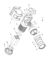
- FIG. 2 is an exploded view of the portable light of FIG. 1 .
- FIG. 3 is a perspective view of the cradle assembly and associated mount for the adjustable light of FIG. 1 .
- FIG. 4 is a perspective view of a portable light including a rotatable cradle and a swiveling mount.
- FIG. 5 is an exploded view of the portable light of FIG. 4 .
- FIG. 6 is a perspective of a portable bicycle light including a rotatable cradle and a swiveling handlebar or frame mount.
- FIG. 7 is an exploded view of the portable bicycle light of FIG. 6 .
- FIG. 1 shows an example portable light 100 adjustably held in a cradle assembly 105 that in turn is secured to a mount 110 .
- Cradle assembly 105 holds a cylindrical housing 115 , which may be better seen in the corresponding exploded view of FIG. 2 .
- Housing 115 provides a longitudinally-extending casing for batteries such as four AA batteries 200 .
- a flashlight bezel 120 projects radially from housing 115 .
- Bezel 120 receives a plurality of LEDs 205 mounted on an LED board 210 .
- bezel 120 also receives a reflector 215 and a lens 220 .
- a retainer 225 is threadably received by bezel 120 to secure lens 220 as well as associated seals 221 and 222 to bezel 120 . Because bezel 120 is directed radially with regard to the longitudinal axis of housing 115 , light will also project radially with regard to this longitudinal axis.
- a user may readily rotate the position of housing 115 (and hence angularly adjust a light beam projected from lens 220 ) with respect to cradle assembly 105 .
- cradle assembly 105 rigidly clamps housing 115 in a fixed orientation.
- the fixed orientation may be one of projecting the light beam orthogonally with respect to a plane formed by mount 110 .
- a user may desire another orientation such that the projected light is tilted with regard to the mount plane, which is readily achieved as described further herein.
- Cradle assembly 105 forms a spring clamp 301 to hold housing 115 such as shown in FIG. 3 .
- clamp 301 includes a center flange 300 that interdigitates between a pair of outer flanges 305 and 310 .
- Each flange ( 300 , 305 and 310 ) ends in a raised tab 320 .
- a user may thus readily pinch center flange 300 towards either of the outer flanges using just two fingers. For example, a thumb may engage tab 320 on outer flange 310 while an index finger engages tab 320 on center flange 300 .
- the user By pinching or biasing these two fingers together, the user not only biases center flange 300 away from outer flange 310 but also from outer flange 305 so as to expand spring clamp 301 . The user could then simultaneously longitudinally move housing 115 away from clamp 301 to free housing 115 so as to use portable light 100 as a conventional hand-held flashlight.
- the conventional flashlight mounting techniques such as through the use of a friction-coupling do not provide such a readily dismountable housing from its cradle.
- an inner surface of spring clamp 301 may include a plurality of elongated ridges 325 configured to engage with corresponding elongated grooves 130 ( FIG. 2 ) on an inner surface of cradle assembly 105 . Both ridges 325 and grooves 130 are aligned with the longitudinal axis of housing 115 . Ridges 325 may circumferentially surround housing 115 such that a user may selectively position housing 15 across a full revolution on its longitudinal axis with respect to cradle assembly 105 .
- housing 115 may be considered to have a set of first engaging features and cradle assembly to have a set of corresponding second engaging features, wherein the first and second sets are configured to engage with each other.
- Mount 110 may comprise a standardized Molle mount so that cradle 105 may be mounted to Molle-compatible vests and other articles.
- housing 115 includes a suitable recess to receive bezel 120 and printed circuit board 230 .
- a distal end of housing 115 receives a switch circuit board 235 and a corresponding switch boot 240 .
- several switches are provided to invoke various operating modes such as variable-output primary LED activation mode, a secondary white-LED illumination mode, a secondary red-LED illumination mode, and a maximum-output primary LED illumination mode.
- Housing 115 may include a straight-edge anti-roll feature 241 to prevent housing 115 from rolling on surfaces when removed from cradle 105 .
- Batteries 200 may be received by corresponding printed circuit boards 245 and 250 .
- a battery compartment cap 255 threadably engages a proximal end of housing 115 to contain batteries 200 within housing 115 .
- Portable light 400 includes a mount 405 that clips onto a user's clothing or other suitable material.
- mount 405 comprises a plurality of cantilever arms 410 that act to bias a captured piece of the user's clothing (e.g., a vest pocket) against a friction pad 415 held in a mounting pad 435 .
- arms 410 may be made resilient such as through the addition of room temperature vulcanizing (RTV) pads 420 .
- An additional cantilever arm 430 may aid in providing friction.
- a cradle assembly 440 holds housing 115 as discussed with regard to cradle assembly 105 of FIGS. 1-3 .
- cradle assembly 440 pivots in the plane defined by mounting pad 435 through the action of a rotational base 445 .
- Rotational base 445 includes a circular opening lined by gear teeth 455 .
- a biased ball detent 450 engages gear teeth 455 .
- Ball detent 450 is biased with regard to a fixed mount 460 so that rotational base 445 can be held in a desired rotation with regard to mounting pad 435 and fixed mount 460 .
- a user thus can both pivot housing 115 about a radial axis defined through mounting pad 435 and also about its longitudinal axis with regard to cradle 440 .
- An analogous pivoting base 605 may be used for portable bicycle light 600 of FIGS. 6 and 7 . Pivoting base 605 mounts through a clamp 610 to a bicycle component such as the handlebars or the frame. There is no need for any cantilever arms to grasp clothing so a cradle 705 holding the housing for light 600 rotatably mounts to clamp 600 through rotational base 445 and fixed base 460 as discussed analogously with regard to portable light 400 of FIGS. 4 and 5 .
Landscapes
- Engineering & Computer Science (AREA)
- General Engineering & Computer Science (AREA)
- Mechanical Engineering (AREA)
- Arrangement Of Elements, Cooling, Sealing, Or The Like Of Lighting Devices (AREA)
- Fastening Of Light Sources Or Lamp Holders (AREA)
- Non-Portable Lighting Devices Or Systems Thereof (AREA)
- Lighting Device Outwards From Vehicle And Optical Signal (AREA)
Abstract
Description
Claims (20)
Priority Applications (3)
| Application Number | Priority Date | Filing Date | Title |
|---|---|---|---|
| US13/737,403 US8911103B2 (en) | 2012-01-13 | 2013-01-09 | Adjustable portable light |
| EP13151025.7A EP2615362B1 (en) | 2012-01-13 | 2013-01-11 | Adjustable portable light |
| CN201310013133.8A CN103206619B (en) | 2012-01-13 | 2013-01-14 | Adjustable portable lamp |
Applications Claiming Priority (2)
| Application Number | Priority Date | Filing Date | Title |
|---|---|---|---|
| US201261586699P | 2012-01-13 | 2012-01-13 | |
| US13/737,403 US8911103B2 (en) | 2012-01-13 | 2013-01-09 | Adjustable portable light |
Publications (2)
| Publication Number | Publication Date |
|---|---|
| US20130182423A1 US20130182423A1 (en) | 2013-07-18 |
| US8911103B2 true US8911103B2 (en) | 2014-12-16 |
Family
ID=47779824
Family Applications (1)
| Application Number | Title | Priority Date | Filing Date |
|---|---|---|---|
| US13/737,403 Active US8911103B2 (en) | 2012-01-13 | 2013-01-09 | Adjustable portable light |
Country Status (3)
| Country | Link |
|---|---|
| US (1) | US8911103B2 (en) |
| EP (1) | EP2615362B1 (en) |
| CN (1) | CN103206619B (en) |
Cited By (13)
| Publication number | Priority date | Publication date | Assignee | Title |
|---|---|---|---|---|
| US20130020786A1 (en) * | 2011-07-21 | 2013-01-24 | Dan Goldwater | Universal mount battery holder for bicycles |
| US20190120469A1 (en) * | 2017-10-24 | 2019-04-25 | Coast Cutlery Co. | Tiltable work light |
| USD859715S1 (en) | 2017-09-28 | 2019-09-10 | Coast Cutlery Co. | Tiltable work light |
| USD895050S1 (en) * | 2017-12-20 | 2020-09-01 | Aimpoint Ab | Sight |
| USD906562S1 (en) * | 2018-11-06 | 2020-12-29 | Streamlight, Inc. | Lighting device |
| US10962180B2 (en) | 2019-08-01 | 2021-03-30 | Walter R. Tucker Enterprises, Ltd. | Handheld clamp work light |
| US11125421B2 (en) | 2019-03-29 | 2021-09-21 | Walter R. Tucker Enterprises, Ltd. | Clamping work light |
| USD956296S1 (en) | 2019-08-01 | 2022-06-28 | Walter T. Tucker Enterprises, Ltd. | Portable clamp light |
| USD974620S1 (en) | 2019-03-29 | 2023-01-03 | Walter R. Tucker Enterprises, Ltd. | Clamping work light |
| US11751673B1 (en) * | 2022-12-18 | 2023-09-12 | Michael H Panosian | Locking screwdriver holder |
| USD1004816S1 (en) | 2020-06-24 | 2023-11-14 | Streamlight, Inc. | Lighting device |
| USD1072303S1 (en) | 2021-11-22 | 2025-04-22 | Milwaukee Electric Tool Corporation | Headlamp |
| US12503186B1 (en) | 2023-06-20 | 2025-12-23 | Joseph Chiarello | Vehicle visibility and safety device and method |
Families Citing this family (18)
| Publication number | Priority date | Publication date | Assignee | Title |
|---|---|---|---|---|
| USD748307S1 (en) | 2012-01-13 | 2016-01-26 | Surefire, Llc | Lighting device |
| CN103953900B (en) * | 2014-05-04 | 2016-06-15 | 邓奎 | A kind of saddle type searchlighting lamp bracket |
| CN105715981B (en) * | 2014-12-02 | 2018-08-31 | 上海星翌国际贸易有限公司 | Mini flashlight and the head lamp for being equipped with mini flashlight |
| WO2017124325A1 (en) * | 2016-01-20 | 2017-07-27 | 邢皓宇 | Alarming device for bicycle |
| CN106996517A (en) * | 2016-01-22 | 2017-08-01 | 宁波福泰电器有限公司 | adjustable head lamp and its application |
| US9846007B2 (en) | 2016-02-25 | 2017-12-19 | Young, Jack & Wright, Inc. | Firearm discharge recording and reporting system |
| CN107477396A (en) * | 2017-08-29 | 2017-12-15 | 佛山市鸿尚得科技有限公司 | A kind of LED flame lamps of waist-belt head |
| US10100989B1 (en) * | 2017-12-05 | 2018-10-16 | SSB Design, Inc. | Dual bicycle headlight and taillight |
| US10337703B1 (en) * | 2018-03-20 | 2019-07-02 | Coast Cutlery Co. | Quick-disconnect flashlight |
| JP6793405B2 (en) * | 2018-10-31 | 2020-12-02 | 株式会社キャットアイ | Light vehicle lights |
| CN111006143A (en) * | 2019-05-15 | 2020-04-14 | 付小龙 | Multifunctional portable miner's lamp |
| US10670201B1 (en) * | 2019-06-19 | 2020-06-02 | 5.11, Inc. | Headlamp with light source on removable slotted body |
| GB202020323D0 (en) * | 2020-12-22 | 2021-02-03 | Sparrow Roger Lionel David | Bicycle light |
| JP7093882B1 (en) | 2021-09-07 | 2022-06-30 | 收 出澤 | Portable LED light |
| USD1024384S1 (en) * | 2022-01-17 | 2024-04-23 | Huizhou Xinyang Outdoor Technology Co., Ltd | Flashlight |
| TWI812242B (en) * | 2022-05-26 | 2023-08-11 | 鋐光實業股份有限公司 | Bicycle handgrip |
| CN116658860A (en) * | 2023-06-25 | 2023-08-29 | 深圳市海洋王公消照明技术有限公司 | Lamp holders and miniature lamps |
| US12146651B1 (en) * | 2024-05-31 | 2024-11-19 | Kai Cao | Luminous object combination device and combination method |
Citations (12)
| Publication number | Priority date | Publication date | Assignee | Title |
|---|---|---|---|---|
| US2361414A (en) * | 1942-08-27 | 1944-10-31 | Jesse A Ramsey | Marine safety light |
| US2402877A (en) * | 1945-01-05 | 1946-06-25 | Earl L Dial | Adjustable flashlight holder |
| US4506317A (en) * | 1984-02-08 | 1985-03-19 | Duddy James J | Magnetic support for flashlight |
| USD324109S (en) * | 1989-05-30 | 1992-02-18 | William Caridi | Magnetic flashlight holder |
| US20020167806A1 (en) * | 2001-05-10 | 2002-11-14 | Thaxton Rocky A. | Flexible leg flashlight holder |
| US20030161139A1 (en) * | 2002-02-25 | 2003-08-28 | Putallaz David C. | Shoulder mount for flashlight |
| US6616294B1 (en) * | 2003-01-07 | 2003-09-09 | David Vincent Henry | Hard hat mounted flashlight holder |
| US20080089058A1 (en) * | 2005-06-28 | 2008-04-17 | Galli Robert D | Flashlight having mating formations for integtration with a rail mounting system |
| US20100165612A1 (en) * | 2008-12-30 | 2010-07-01 | Hsueh-Chu Yeh | Flashlight |
| US20120182727A1 (en) * | 2011-01-13 | 2012-07-19 | Sharrah Raymond L | Portable light with hanger, clip and led module |
| US20120236543A1 (en) * | 2011-03-14 | 2012-09-20 | Mark Cameron Torgerson | Flashclip |
| US8360597B1 (en) * | 2007-11-01 | 2013-01-29 | Neville Blake Hanchett | Light mounting apparatus |
Family Cites Families (4)
| Publication number | Priority date | Publication date | Assignee | Title |
|---|---|---|---|---|
| US6905223B2 (en) * | 2000-08-10 | 2005-06-14 | Mag Instrument, Inc. | Flashlight |
| CN2846992Y (en) * | 2005-11-25 | 2006-12-13 | 张磊 | LED head lamp |
| US20100277894A1 (en) * | 2009-05-01 | 2010-11-04 | Kim Paul Y | Lighting device with removable cradle |
| CN201992351U (en) * | 2011-01-28 | 2011-09-28 | 深圳市朗恒电子有限公司 | Multifunctional clamped-in type lighting device with rotational structure |
-
2013
- 2013-01-09 US US13/737,403 patent/US8911103B2/en active Active
- 2013-01-11 EP EP13151025.7A patent/EP2615362B1/en active Active
- 2013-01-14 CN CN201310013133.8A patent/CN103206619B/en active Active
Patent Citations (12)
| Publication number | Priority date | Publication date | Assignee | Title |
|---|---|---|---|---|
| US2361414A (en) * | 1942-08-27 | 1944-10-31 | Jesse A Ramsey | Marine safety light |
| US2402877A (en) * | 1945-01-05 | 1946-06-25 | Earl L Dial | Adjustable flashlight holder |
| US4506317A (en) * | 1984-02-08 | 1985-03-19 | Duddy James J | Magnetic support for flashlight |
| USD324109S (en) * | 1989-05-30 | 1992-02-18 | William Caridi | Magnetic flashlight holder |
| US20020167806A1 (en) * | 2001-05-10 | 2002-11-14 | Thaxton Rocky A. | Flexible leg flashlight holder |
| US20030161139A1 (en) * | 2002-02-25 | 2003-08-28 | Putallaz David C. | Shoulder mount for flashlight |
| US6616294B1 (en) * | 2003-01-07 | 2003-09-09 | David Vincent Henry | Hard hat mounted flashlight holder |
| US20080089058A1 (en) * | 2005-06-28 | 2008-04-17 | Galli Robert D | Flashlight having mating formations for integtration with a rail mounting system |
| US8360597B1 (en) * | 2007-11-01 | 2013-01-29 | Neville Blake Hanchett | Light mounting apparatus |
| US20100165612A1 (en) * | 2008-12-30 | 2010-07-01 | Hsueh-Chu Yeh | Flashlight |
| US20120182727A1 (en) * | 2011-01-13 | 2012-07-19 | Sharrah Raymond L | Portable light with hanger, clip and led module |
| US20120236543A1 (en) * | 2011-03-14 | 2012-09-20 | Mark Cameron Torgerson | Flashclip |
Non-Patent Citations (1)
| Title |
|---|
| U.S. Appl. No. 29/410,908, filed Jan. 13, 2012, Inventors: Matthews et al., 17 pages. |
Cited By (15)
| Publication number | Priority date | Publication date | Assignee | Title |
|---|---|---|---|---|
| US9174691B2 (en) * | 2011-07-21 | 2015-11-03 | Dan Goldwater | Universal mount battery holder for bicycles |
| US20130020786A1 (en) * | 2011-07-21 | 2013-01-24 | Dan Goldwater | Universal mount battery holder for bicycles |
| USD859715S1 (en) | 2017-09-28 | 2019-09-10 | Coast Cutlery Co. | Tiltable work light |
| US20190120469A1 (en) * | 2017-10-24 | 2019-04-25 | Coast Cutlery Co. | Tiltable work light |
| USD895050S1 (en) * | 2017-12-20 | 2020-09-01 | Aimpoint Ab | Sight |
| USD906562S1 (en) * | 2018-11-06 | 2020-12-29 | Streamlight, Inc. | Lighting device |
| USD956165S1 (en) | 2018-11-06 | 2022-06-28 | Streamlight, Inc. | Lighting device |
| USD974620S1 (en) | 2019-03-29 | 2023-01-03 | Walter R. Tucker Enterprises, Ltd. | Clamping work light |
| US11125421B2 (en) | 2019-03-29 | 2021-09-21 | Walter R. Tucker Enterprises, Ltd. | Clamping work light |
| US10962180B2 (en) | 2019-08-01 | 2021-03-30 | Walter R. Tucker Enterprises, Ltd. | Handheld clamp work light |
| USD956296S1 (en) | 2019-08-01 | 2022-06-28 | Walter T. Tucker Enterprises, Ltd. | Portable clamp light |
| USD1004816S1 (en) | 2020-06-24 | 2023-11-14 | Streamlight, Inc. | Lighting device |
| USD1072303S1 (en) | 2021-11-22 | 2025-04-22 | Milwaukee Electric Tool Corporation | Headlamp |
| US11751673B1 (en) * | 2022-12-18 | 2023-09-12 | Michael H Panosian | Locking screwdriver holder |
| US12503186B1 (en) | 2023-06-20 | 2025-12-23 | Joseph Chiarello | Vehicle visibility and safety device and method |
Also Published As
| Publication number | Publication date |
|---|---|
| US20130182423A1 (en) | 2013-07-18 |
| CN103206619B (en) | 2017-03-01 |
| CN103206619A (en) | 2013-07-17 |
| EP2615362A2 (en) | 2013-07-17 |
| EP2615362B1 (en) | 2019-06-12 |
| EP2615362A3 (en) | 2017-07-05 |
Similar Documents
| Publication | Publication Date | Title |
|---|---|---|
| US8911103B2 (en) | Adjustable portable light | |
| US8764253B2 (en) | Hands-free multi-positional task light and method of use thereof | |
| US6953259B2 (en) | Adjustable flashlight case | |
| US10962327B2 (en) | Multidirectional firearm light | |
| EP1959188B1 (en) | Flashlight with rotatable handle | |
| US9995442B2 (en) | Multi-function portable lighting apparatus | |
| US9599312B2 (en) | Portable lamp | |
| US8714769B2 (en) | Light system | |
| US8540404B2 (en) | Flashlight with retractable cord and attachment device | |
| CN101876400A (en) | Lighting device with removable cradle | |
| US7163314B2 (en) | Flashlight having an adjustable grip | |
| US10465887B1 (en) | Cap light | |
| US20050152134A1 (en) | Convertible flashlight | |
| JP5740071B2 (en) | Portable luminaire with rotatable cylindrical head | |
| CN205716887U (en) | Multiple working angle shoulder lamp | |
| US20140293572A1 (en) | Photography lighting fixture | |
| US20110141750A1 (en) | Track lighting fixture | |
| CN113776003B (en) | A zoomable fishing light | |
| US7905629B2 (en) | Spotlight with user-friendly fixable adjustable focus | |
| TWI790521B (en) | Pivoting swivel illumination device | |
| CN109424889A (en) | Antiexplosive working lamp | |
| CN219775502U (en) | Portable lamp | |
| CN217519698U (en) | Portable miniature pen lamp | |
| JP2025006992A (en) | Hand Light | |
| RU2568252C1 (en) | Miniature led flashlight with fastener (versions) |
Legal Events
| Date | Code | Title | Description |
|---|---|---|---|
| AS | Assignment |
Owner name: SUREFIRE, LLC, CALIFORNIA Free format text: ASSIGNMENT OF ASSIGNORS INTEREST;ASSIGNORS:MATTHEWS, JOHN W.;GIBSON, RONALD S.;ANDERSON, MICHAEL D.;AND OTHERS;SIGNING DATES FROM 20070529 TO 20130219;REEL/FRAME:034111/0518 |
|
| STCF | Information on status: patent grant |
Free format text: PATENTED CASE |
|
| MAFP | Maintenance fee payment |
Free format text: PAYMENT OF MAINTENANCE FEE, 4TH YR, SMALL ENTITY (ORIGINAL EVENT CODE: M2551) Year of fee payment: 4 |
|
| MAFP | Maintenance fee payment |
Free format text: PAYMENT OF MAINTENANCE FEE, 8TH YR, SMALL ENTITY (ORIGINAL EVENT CODE: M2552); ENTITY STATUS OF PATENT OWNER: SMALL ENTITY Year of fee payment: 8 |