US8908358B2 - Protection case for electronic device - Google Patents

Protection case for electronic device Download PDF

Info

Publication number
US8908358B2
US8908358B2 US13/587,977 US201213587977A US8908358B2 US 8908358 B2 US8908358 B2 US 8908358B2 US 201213587977 A US201213587977 A US 201213587977A US 8908358 B2 US8908358 B2 US 8908358B2
Authority
US
United States
Prior art keywords
holes
interface
electronic device
plug
speaker
Prior art date
Legal status (The legal status is an assumption and is not a legal conclusion. Google has not performed a legal analysis and makes no representation as to the accuracy of the status listed.)
Expired - Fee Related, expires
Application number
US13/587,977
Other versions
US20130153451A1 (en
Inventor
Zhou Chen
Current Assignee (The listed assignees may be inaccurate. Google has not performed a legal analysis and makes no representation or warranty as to the accuracy of the list.)
Futaihua Industry Shenzhen Co Ltd
Hon Hai Precision Industry Co Ltd
Original Assignee
Futaihua Industry Shenzhen Co Ltd
Hon Hai Precision Industry Co Ltd
Priority date (The priority date is an assumption and is not a legal conclusion. Google has not performed a legal analysis and makes no representation as to the accuracy of the date listed.)
Filing date
Publication date
Application filed by Futaihua Industry Shenzhen Co Ltd, Hon Hai Precision Industry Co Ltd filed Critical Futaihua Industry Shenzhen Co Ltd
Assigned to HON HAI PRECISION INDUSTRY CO., LTD., Fu Tai Hua Industry (Shenzhen) Co., Ltd. reassignment HON HAI PRECISION INDUSTRY CO., LTD. ASSIGNMENT OF ASSIGNORS INTEREST (SEE DOCUMENT FOR DETAILS). Assignors: CHEN, Zhou
Publication of US20130153451A1 publication Critical patent/US20130153451A1/en
Application granted granted Critical
Publication of US8908358B2 publication Critical patent/US8908358B2/en
Expired - Fee Related legal-status Critical Current
Adjusted expiration legal-status Critical

Links

Images

Classifications

    • AHUMAN NECESSITIES
    • A45HAND OR TRAVELLING ARTICLES
    • A45CPURSES; LUGGAGE; HAND CARRIED BAGS
    • A45C13/00Details; Accessories
    • A45C13/002Protective covers
    • GPHYSICS
    • G06COMPUTING OR CALCULATING; COUNTING
    • G06FELECTRIC DIGITAL DATA PROCESSING
    • G06F2200/00Indexing scheme relating to G06F1/04 - G06F1/32
    • G06F2200/16Indexing scheme relating to G06F1/16 - G06F1/18
    • G06F2200/163Indexing scheme relating to constructional details of the computer
    • G06F2200/1633Protecting arrangement for the entire housing of the computer

Definitions

  • the disclosure generally relates to cases, and particularly to a protection case for an electronic device.
  • An electronic device may be put in a case for avoiding dust and reducing collision damage.
  • many other factors also have an effect on the electronic devices. For example, when the electronic device is placed in a humid environment, moisture in the atmosphere may cause damage to the electronic device.
  • FIG. 1 is an isometric view of a protection case and an electronic device in accordance with a first embodiment of the present disclosure.
  • FIG. 2 is another isometric view of the protection case of FIG. 1 .
  • FIG. 3 is an isometric view of the protection case of FIG. 1 when the electronic device is accommodated in the protection case.
  • FIG. 4 is an enlarged, isometric view of a portion IV of FIG. 1 .
  • FIG. 5 is an enlarged, isometric view of a portion V of FIG. 2 .
  • FIG. 6 is an isometric view of a second plug of the protection case of FIG. 1 .
  • FIG. 7 is a cross-sectional, isometric view taken along the line VII-VII of FIG. 3 .
  • a protection case 1 for an electronic device 3 includes a main body 10 and a number of plugs 20 .
  • the main body 10 defines a receiving cavity 105 for accommodating the electronic device 3 and a number of connecting holes 100 corresponding to a number of ports (not shown) on the electronic device 3 , such as a power port, an audio jack, and an universal serial bus (USB) port.
  • the shape of each connecting hole 100 matches with the type of plug 20 for which it is intended, and each shape of the plug 20 matches with a connecting hole 100 .
  • the plug 20 is insertable into the connecting hole 100 to prevent moisture and any other air-borne contaminants from entering into the electronic device 3 when accommodated in the protection case 1 , when the port is not in use.
  • the main body 10 may be made of a resilient material, so that the size of the receiving cavity 105 can be stretched to adapt to different sizes.
  • the original size of the receiving cavity 105 is slightly smaller than or the same size as the electronic device 3 .
  • the receiving cavity 105 will be enlarged by the electronic device 3 , and an interior surface of the receiving cavity 105 closely hugs an exterior surface of the electronic device 3 .
  • the main body 10 is made of a soft resin which is resistant to electromagnetic interference or radiation (EMI/R), such as a vinyl acetate ethylene acetate polymerization, for preventing the entry or output of EMI/R in relation to the electronic device 3 .
  • EMI/R electromagnetic interference or radiation
  • the main body 10 includes a first surface 101 , a second surface 102 parallel to the first surface 101 , and a sidewall 104 perpendicularly connected to the first surface 101 and the second surface 102 .
  • the first surface 101 defines an opening 1010 corresponding to a display screen 30 of the electronic device 3 .
  • the connecting holes 100 can be defined in the first surface 101 , the second surface 102 , and/or the sidewall 104 .
  • the main body 10 further defines a receiving groove 103 surrounding each of the connecting holes 100 whereby moisture can pass.
  • the connecting holes 100 may be, but are not limited to, a number of first speaker through holes 1000 , a pair of second speaker through holes 1001 , a first interface through hole 1002 for exposing the USB port, and a second interface through hole 1003 for exposing the audio jack.
  • the receiving grooves 103 may be, but are not limited to, a first receiving groove 1030 encircling the first speaker through hole 1000 , and a second receiving groove 1031 encircling the first interface through hole 1002 and the second interface through hole 1003 .
  • the plugs 20 may be, but are not limited to, a pair of first plugs 201 for engaging with the second speaker through hole 1001 and a second plug 202 for engaging with the second receiving groove 1031 .
  • the first receiving groove 1030 is defined in the second surface 102 and corresponds to a number of speakers 32 of the electronic device 3 .
  • a number of protrusions 100 a are formed on a bottom surface of the first receiving groove 1030 .
  • the first speaker through holes 1000 are defined through each protrusion 100 a so as to allow communication between the speaker 32 and the exterior of the protective cover 1 .
  • the second speaker through hole 1001 is defined in the sidewall 104 and also corresponds to the speaker 32 of the electronic device 3 .
  • the second speaker through hole 1001 communicates with the first speaker through holes 1000 .
  • the second speaker through hole 1001 includes a pair of parallel internal side surfaces 1001 a .
  • the internal side surfaces 1001 a are perpendicular to the sidewall 104 and extend from the sidewall 104 to the receiving cavity 105 .
  • a pair of positioning projections 1001 d are formed on each internal side surface 1001 a.
  • the first plug 201 includes a base board 2010 and a plug body 2012 extending from the base board 2010 .
  • the plug body 2012 is substantially rectangular, and includes an end surface 2012 a opposite to the base board 2010 , a pair of parallel outer side surfaces 2012 b , a top surface 2012 c perpendicular to the outer side surface 2012 b , and a bottom surface 2012 d parallel to the top surface 2012 c .
  • the end surface 2012 a is shaped to match the shape of the speaker 32 of the electronic device 3 .
  • the plug body 2012 defines a positioning dimple 2012 e in each outer side surface 2012 b .
  • the end surface 2012 a is tightly attached on the speaker 32 to cover a number of holes 34 of the speaker 32 .
  • the top surface 2012 c faces and covers the first speaker through holes 1000 formed in the second surface 102 .
  • the positioning projections 1001 d is inserted into the positioning dimples 2012 e in the internal side surfaces 1001 a to fasten the first plugs 201 in the second speaker through holes 1001 .
  • the second receiving groove 1031 is defined in the sidewall 104 and corresponds to the USB port and the audio jack of the electronic device 3 .
  • the second receiving groove 1031 is substantially rectangular and includes an inner sidewall 1031 a and a bottom wall 1031 b perpendicular to the inner sidewall 1031 a .
  • the main body 10 defines a pair of positioning cutouts 1031 c at two parallel longer peripheries of the inner sidewall 1031 a .
  • the first interface through hole 1002 and the second interface through hole 1003 are defined in the bottom wall 1031 b .
  • the main body 10 defines a receiving channel 1031 d surrounding the first interface through hole 1002 and the second interface through hole 1003 .
  • the first interface through hole 1002 is substantially rectangular.
  • the second interface through hole 1003 is circular.
  • the second plug 202 is substantially rectangular and includes an inner wall 2023 , an outer wall 2024 parallel to the inner wall 2023 , a first protrusion 2020 for being engagably inserted into the first interface through hole 1002 , and a second protrusion 2022 for being engagably inserted into the second interface through hole 1003 .
  • the second plug 202 forms a sealing protrusion 2026 extending along the periphery of the inner wall 2023 .
  • the sealing protrusion 2026 surrounds the first protrusion 2020 and the second protrusion 2022 .
  • the second plug 202 further forms a pair of positioning protrusions 2027 at the two longer peripheries of the outer wall 2024 .
  • the first protrusion 2020 is inserted into the first interface through hole 1002 .
  • the second protrusion 2022 is inserted into the second interface through hole 1003 .
  • the sealing protrusion 2026 is inserted into the receiving channel 1031 d .
  • the positioning protrusions 2027 are correspondingly inserted into the positioning cutouts 1031 c to fasten the second plug 202 into the second receiving groove 1031 .
  • the positions of the first receiving groove 1030 and the second receiving groove 1031 , the quantity of the connecting holes 100 in the first receiving groove 1030 and the second receiving groove 1031 , the shape of the connecting holes 100 , and the structure of the plugs 20 can be changed according to the position and the shape of the ports and other parts of the electronic device 3 .

Landscapes

  • Casings For Electric Apparatus (AREA)
  • Connector Housings Or Holding Contact Members (AREA)

Abstract

A protection case for protecting an electronic device is disclosed. The protection case includes a main body. The main body defines a receiving cavity for accommodating the electronic device and a plurality of connecting through holes for exposing a plurality of interface ports of the electronic device. The main body defines a number of grooves encircling the connecting through holes for receiving moisture in the air.

Description

TECHNICAL FIELD
The disclosure generally relates to cases, and particularly to a protection case for an electronic device.
DESCRIPTION OF RELATED ART
An electronic device may be put in a case for avoiding dust and reducing collision damage. However, many other factors also have an effect on the electronic devices. For example, when the electronic device is placed in a humid environment, moisture in the atmosphere may cause damage to the electronic device.
Therefore, it is desirable to provide a protection case which can overcome the above-mentioned problems.
BRIEF DESCRIPTION OF THE DRAWINGS
Many aspects of the disclosure can be better understood with reference to the following drawings. The components in the drawings are not necessarily drawn to scale, the emphasis instead being placed upon clearly illustrating the principles of the disclosure. Moreover, in the drawings, like reference numerals designate corresponding portions throughout the several views.
FIG. 1 is an isometric view of a protection case and an electronic device in accordance with a first embodiment of the present disclosure.
FIG. 2 is another isometric view of the protection case of FIG. 1.
FIG. 3 is an isometric view of the protection case of FIG. 1 when the electronic device is accommodated in the protection case.
FIG. 4 is an enlarged, isometric view of a portion IV of FIG. 1.
FIG. 5 is an enlarged, isometric view of a portion V of FIG. 2.
FIG. 6 is an isometric view of a second plug of the protection case of FIG. 1.
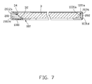
FIG. 7 is a cross-sectional, isometric view taken along the line VII-VII of FIG. 3.
DETAILED DESCRIPTION
The disclosure is illustrated by way of example and not by way of limitation in the figures of the accompanying drawings in which like references indicate similar elements. It should be noted that references to “an” or “one” embodiment in this disclosure are not necessarily to the same embodiment, and such references mean “at least one”.
Referring to FIGS. 1 to 3, in one embodiment, a protection case 1 for an electronic device 3 includes a main body 10 and a number of plugs 20. The main body 10 defines a receiving cavity 105 for accommodating the electronic device 3 and a number of connecting holes 100 corresponding to a number of ports (not shown) on the electronic device 3, such as a power port, an audio jack, and an universal serial bus (USB) port. The shape of each connecting hole 100 matches with the type of plug 20 for which it is intended, and each shape of the plug 20 matches with a connecting hole 100. The plug 20 is insertable into the connecting hole 100 to prevent moisture and any other air-borne contaminants from entering into the electronic device 3 when accommodated in the protection case 1, when the port is not in use.
The main body 10 may be made of a resilient material, so that the size of the receiving cavity 105 can be stretched to adapt to different sizes. The original size of the receiving cavity 105 is slightly smaller than or the same size as the electronic device 3. When the electronic device 3 is accommodated into the receiving cavity 105, the receiving cavity 105 will be enlarged by the electronic device 3, and an interior surface of the receiving cavity 105 closely hugs an exterior surface of the electronic device 3. In one embodiment, the main body 10 is made of a soft resin which is resistant to electromagnetic interference or radiation (EMI/R), such as a vinyl acetate ethylene acetate polymerization, for preventing the entry or output of EMI/R in relation to the electronic device 3.
The main body 10 includes a first surface 101, a second surface 102 parallel to the first surface 101, and a sidewall 104 perpendicularly connected to the first surface 101 and the second surface 102. The first surface 101 defines an opening 1010 corresponding to a display screen 30 of the electronic device 3. The connecting holes 100 can be defined in the first surface 101, the second surface 102, and/or the sidewall 104. The main body 10 further defines a receiving groove 103 surrounding each of the connecting holes 100 whereby moisture can pass. The connecting holes 100 may be, but are not limited to, a number of first speaker through holes 1000, a pair of second speaker through holes 1001, a first interface through hole 1002 for exposing the USB port, and a second interface through hole 1003 for exposing the audio jack. The receiving grooves 103 may be, but are not limited to, a first receiving groove 1030 encircling the first speaker through hole 1000, and a second receiving groove 1031 encircling the first interface through hole 1002 and the second interface through hole 1003. The plugs 20 may be, but are not limited to, a pair of first plugs 201 for engaging with the second speaker through hole 1001 and a second plug 202 for engaging with the second receiving groove 1031.
Referring to FIGS. 5 and 7, the first receiving groove 1030 is defined in the second surface 102 and corresponds to a number of speakers 32 of the electronic device 3. A number of protrusions 100 a are formed on a bottom surface of the first receiving groove 1030. The first speaker through holes 1000 are defined through each protrusion 100 a so as to allow communication between the speaker 32 and the exterior of the protective cover 1. The second speaker through hole 1001 is defined in the sidewall 104 and also corresponds to the speaker 32 of the electronic device 3. The second speaker through hole 1001 communicates with the first speaker through holes 1000. The second speaker through hole 1001 includes a pair of parallel internal side surfaces 1001 a. The internal side surfaces 1001 a are perpendicular to the sidewall 104 and extend from the sidewall 104 to the receiving cavity 105. A pair of positioning projections 1001 d are formed on each internal side surface 1001 a.
The first plug 201 includes a base board 2010 and a plug body 2012 extending from the base board 2010. The plug body 2012 is substantially rectangular, and includes an end surface 2012 a opposite to the base board 2010, a pair of parallel outer side surfaces 2012 b, a top surface 2012 c perpendicular to the outer side surface 2012 b, and a bottom surface 2012 d parallel to the top surface 2012 c. The end surface 2012 a is shaped to match the shape of the speaker 32 of the electronic device 3. The plug body 2012 defines a positioning dimple 2012 e in each outer side surface 2012 b. When the first plug 201 is inserted into the second speaker through hole 1001, the end surface 2012 a is tightly attached on the speaker 32 to cover a number of holes 34 of the speaker 32. The top surface 2012 c faces and covers the first speaker through holes 1000 formed in the second surface 102. The positioning projections 1001 d is inserted into the positioning dimples 2012 e in the internal side surfaces 1001 a to fasten the first plugs 201 in the second speaker through holes 1001.
Referring to FIGS. 4 and 7, the second receiving groove 1031 is defined in the sidewall 104 and corresponds to the USB port and the audio jack of the electronic device 3. The second receiving groove 1031 is substantially rectangular and includes an inner sidewall 1031 a and a bottom wall 1031 b perpendicular to the inner sidewall 1031 a. The main body 10 defines a pair of positioning cutouts 1031 c at two parallel longer peripheries of the inner sidewall 1031 a. The first interface through hole 1002 and the second interface through hole 1003 are defined in the bottom wall 1031 b. The main body 10 defines a receiving channel 1031 d surrounding the first interface through hole 1002 and the second interface through hole 1003. In this embodiment, the first interface through hole 1002 is substantially rectangular. The second interface through hole 1003 is circular.
Referring to FIGS. 4 and 6, the second plug 202 is substantially rectangular and includes an inner wall 2023, an outer wall 2024 parallel to the inner wall 2023, a first protrusion 2020 for being engagably inserted into the first interface through hole 1002, and a second protrusion 2022 for being engagably inserted into the second interface through hole 1003. The second plug 202 forms a sealing protrusion 2026 extending along the periphery of the inner wall 2023. The sealing protrusion 2026 surrounds the first protrusion 2020 and the second protrusion 2022. The second plug 202 further forms a pair of positioning protrusions 2027 at the two longer peripheries of the outer wall 2024. When the second plug 202 is inserted into the second receiving groove 1031, the first protrusion 2020 is inserted into the first interface through hole 1002. The second protrusion 2022 is inserted into the second interface through hole 1003. The sealing protrusion 2026 is inserted into the receiving channel 1031 d. The positioning protrusions 2027 are correspondingly inserted into the positioning cutouts 1031 c to fasten the second plug 202 into the second receiving groove 1031.
Referring to FIGS. 1 and 2, the positions of the first receiving groove 1030 and the second receiving groove 1031, the quantity of the connecting holes 100 in the first receiving groove 1030 and the second receiving groove 1031, the shape of the connecting holes 100, and the structure of the plugs 20 can be changed according to the position and the shape of the ports and other parts of the electronic device 3.
It is believed that the present embodiments and their advantages will be understood from the foregoing description, and it will be apparent that various changes may be made thereto without departing from the spirit and scope of the disclosure or sacrificing all of its material advantages, the examples hereinbefore described merely being preferred or exemplary embodiments of the disclosure.

Claims (13)

What is claimed is:
1. A protection case for protecting an electronic device, the protection case comprising:
a main body, the main body defining a receiving cavity for accommodating the electronic device and a plurality of connecting holes for exposing a plurality of ports of the electronic device, the main body comprising a first surface, a second surface parallel to the first surface, and a sidewall perpendicularly connected to the first surface and the second surface;
wherein the main body defines a plurality of grooves encircling the connecting holes, the connecting holes comprise a plurality of first speaker through holes defined in the second surface and corresponding to a plurality of speakers of the electronic device, the grooves comprise a first receiving groove defined in the second surface, a plurality of speaker protrusions are formed on a bottom surface of the first receiving groove, the first speaker through holes are defined through the speaker protrusions.
2. The protection case of claim 1, wherein the connecting holes comprise a plurality of interface through holes, a second plug for engagably inserting into one of the grooves, the second plug comprising a plurality of protrusions corresponding to the interface through holes, and when the second plug is inserted into the one of the grooves, the protrusions are inserted into the corresponding interface through holes.
3. The protection case of claim 2, wherein the first surface defines an opening for exposing a display screen of the electronic device.
4. The protection case of claim 3, wherein the interface through holes comprise a first interface through hole for exposing a universal serial bus port of the electronic device and a second interface through hole for exposing an audio jack of the electronic device, the plurality of grooves further comprise a second receiving groove defined in the sidewall, and the first interface through hole and the second interface through hole are defined in the second receiving groove.
5. The protection case of claim 4, wherein the second plug is for sealing the second receiving groove, the second plug comprises an inner wall, an outer wall parallel to the inner wall, a first protrusion for engaging with the first interface through hole, and a second protrusion for engaging with the second interface through hole.
6. The protection case of claim 5, wherein the second receiving groove comprises an inner sidewall and a bottom wall perpendicular to the inner sidewall, the main body defines a pair of positioning cutouts correspondingly at two parallel peripheries of the inner sidewall, the second plug forms a pair of positioning protrusions at two peripheries of the outer wall, when the second plug is inserted into the second receiving groove, the positioning protrusions are correspondingly inserted into the positioning cutouts to fasten the second plug into the second receiving groove.
7. The protection case of claim 6, wherein the main body defines a receiving channel encircling the first interface through hole and the second interface through hole in the bottom wall, the second plug forms a sealing protrusion extending along the periphery of the inner wall and encircles the first protrusion and the second protrusion, when the second plug is inserted into the second receiving groove, the sealing protrusion is inserted into the receiving channel.
8. The protection case of claim 7, wherein the first interface through hole is substantially rectangular, the second interface through hole is circular.
9. The protection case of claim 8, wherein the main body is made of a soft resin which is resistant to electromagnetic interference or radiation.
10. The protection case of claim 1, wherein the connecting holes further comprise a plurality of second speaker through holes defined in the sidewall and corresponds to the speakers of the electronic device, each of the second speaker through holes communicate with a corresponding one of the first speaker through holes, the protection case further comprise a plurality of first plugs for engagably inserted into the second speaker through holes and breaking the communication between the speakers and the first speaker through holes, each of the first plugs comprises a base board and a plug body extending from the base board, the plug body defines a positioning dimple in a pair of parallel outer side surface of plug body.
11. The protection case of claim 10, wherein each of the second speaker through holes comprises a pair of parallel internal side surfaces, the internal side surfaces are perpendicular to the sidewall and extend from the sidewall to the receiving cavity, a pair of positioning projections are correspondingly formed on the internal side surfaces, the positioning projections are correspondingly inserted into the positioning dimples to fasten the first plugs in the second speaker through holes.
12. A case for protecting an electronic device, comprising:
a main body covering at least a portion of the electronic device, the main body comprising a first surface, a second surface parallel to the first surface, and a sidewall perpendicularly connected to the first surface and the second surface;
a plurality of connecting through holes defined in the main body corresponding to a plurality of speakers of the electronic device; and
a groove defined in the second surface,
wherein the connecting through holes is located in the groove, moisture existing in the air is gathered in the groove, a plurality of protrusions are formed on a bottom surface of the groove, the connecting through holes are defined through the protrusions.
13. The case of claim 12, wherein each protrusion is formed at a top end of a respective one of the connecting through holes.
US13/587,977 2011-12-19 2012-08-17 Protection case for electronic device Expired - Fee Related US8908358B2 (en)

Applications Claiming Priority (3)

Application Number Priority Date Filing Date Title
CN201110426558 2011-12-19
CN201110426558.2 2011-12-19
CN201110426558.2A CN103156369B (en) 2011-12-19 2011-12-19 Protection set

Publications (2)

Publication Number Publication Date
US20130153451A1 US20130153451A1 (en) 2013-06-20
US8908358B2 true US8908358B2 (en) 2014-12-09

Family

ID=48580282

Family Applications (1)

Application Number Title Priority Date Filing Date
US13/587,977 Expired - Fee Related US8908358B2 (en) 2011-12-19 2012-08-17 Protection case for electronic device

Country Status (3)

Country Link
US (1) US8908358B2 (en)
CN (1) CN103156369B (en)
TW (1) TWI539257B (en)

Families Citing this family (5)

* Cited by examiner, † Cited by third party
Publication number Priority date Publication date Assignee Title
CN104918432A (en) * 2014-03-12 2015-09-16 富士康(昆山)电脑接插件有限公司 Protective housing and assembly thereof
US20160021766A1 (en) * 2014-07-15 2016-01-21 Vikramaditya Jain Dual portable electronic device carrying case
CN106101349A (en) * 2016-08-19 2016-11-09 金陵科技学院 A kind of smart mobile phone set of anti-electromagnetic-radiation
CN107395841A (en) * 2017-08-17 2017-11-24 广东欧珀移动通信有限公司 Shell and mobile terminal
CN114257675A (en) * 2021-11-11 2022-03-29 荣耀终端有限公司 Protective sleeve of electronic product and electronic equipment

Citations (2)

* Cited by examiner, † Cited by third party
Publication number Priority date Publication date Assignee Title
US7267550B1 (en) * 2006-11-29 2007-09-11 International Business Machines Corporation Printed circuit board capable of receiving an on-board battery from multiple orientations
US7495895B2 (en) * 2006-04-19 2009-02-24 Carnevali Jeffrey D Protective cover for device having touch screen

Family Cites Families (3)

* Cited by examiner, † Cited by third party
Publication number Priority date Publication date Assignee Title
JP2007066746A (en) * 2005-08-31 2007-03-15 Fujitsu Ltd Housing drainage structure and electronic equipment
CN2935637Y (en) * 2006-06-23 2007-08-15 高伟文 Handset cover
CN202019941U (en) * 2011-03-23 2011-11-02 淼创意者有限公司 Protective Cases for Handheld Electronic Devices

Patent Citations (2)

* Cited by examiner, † Cited by third party
Publication number Priority date Publication date Assignee Title
US7495895B2 (en) * 2006-04-19 2009-02-24 Carnevali Jeffrey D Protective cover for device having touch screen
US7267550B1 (en) * 2006-11-29 2007-09-11 International Business Machines Corporation Printed circuit board capable of receiving an on-board battery from multiple orientations

Also Published As

Publication number Publication date
TWI539257B (en) 2016-06-21
CN103156369B (en) 2016-06-29
TW201327091A (en) 2013-07-01
US20130153451A1 (en) 2013-06-20
CN103156369A (en) 2013-06-19

Similar Documents

Publication Publication Date Title
US8908358B2 (en) Protection case for electronic device
EP4101149B1 (en) Protective sleeve for a mobile device comprising an inner connector adapted to the mobile device and an external connector for appliances
US8002564B2 (en) Housing of portable electronic device
US9612632B2 (en) Wireless electronic device with component cooling structures
US20100033913A1 (en) Interface protective cover of electronic device
US20080268725A1 (en) Dustproof cover for electrical connector
US20140158559A1 (en) Protective case for portable electronic device
KR20130097557A (en) Apparatus for waterproofing ear jack in mobile terminal
US20110182022A1 (en) Waterproof casing with multiple isolated compartments
CN102377056A (en) Audio connector and audio plug thereof
CN214797582U (en) Sealing structure for battery cover of remote controller
US8801465B2 (en) USB device with strengthened housing
CN205726720U (en) Cases for Portable Electronic Devices
CN102045969A (en) Electronic device
US20120152966A1 (en) Protective cover for electronic device
US20120225572A1 (en) Electronic device and infrared receiving device thereof
JP3203594U (en) Casing having fastening structure
US9048602B2 (en) Audio-visual connector
KR200469611Y1 (en) Watertight audio jack
CN201104362Y (en) Earphone protective sleeve
TWI482563B (en) Electronic device and housing assembly
CN211400012U (en) An air conditioner indoor unit
CN204887741U (en) Power Supplier
KR20140003586U (en) Mobile phone case with earphone terminal protective caps and charging terminal protective caps
KR20240009183A (en) Motorcycle battery controller with protective electrical connections

Legal Events

Date Code Title Description
AS Assignment

Owner name: HON HAI PRECISION INDUSTRY CO., LTD., TAIWAN

Free format text: ASSIGNMENT OF ASSIGNORS INTEREST;ASSIGNOR:CHEN, ZHOU;REEL/FRAME:028802/0733

Effective date: 20120808

Owner name: FU TAI HUA INDUSTRY (SHENZHEN) CO., LTD., CHINA

Free format text: ASSIGNMENT OF ASSIGNORS INTEREST;ASSIGNOR:CHEN, ZHOU;REEL/FRAME:028802/0733

Effective date: 20120808

FEPP Fee payment procedure

Free format text: MAINTENANCE FEE REMINDER MAILED (ORIGINAL EVENT CODE: REM.)

LAPS Lapse for failure to pay maintenance fees

Free format text: PATENT EXPIRED FOR FAILURE TO PAY MAINTENANCE FEES (ORIGINAL EVENT CODE: EXP.); ENTITY STATUS OF PATENT OWNER: LARGE ENTITY

STCH Information on status: patent discontinuation

Free format text: PATENT EXPIRED DUE TO NONPAYMENT OF MAINTENANCE FEES UNDER 37 CFR 1.362

FP Expired due to failure to pay maintenance fee

Effective date: 20181209