US8907926B2 - Method for calibrating accuracy of optical touch monitor - Google Patents
Method for calibrating accuracy of optical touch monitor Download PDFInfo
- Publication number
- US8907926B2 US8907926B2 US13/198,727 US201113198727A US8907926B2 US 8907926 B2 US8907926 B2 US 8907926B2 US 201113198727 A US201113198727 A US 201113198727A US 8907926 B2 US8907926 B2 US 8907926B2
- Authority
- US
- United States
- Prior art keywords
- touch
- image
- matrix
- monitor
- lens
- Prior art date
- Legal status (The legal status is an assumption and is not a legal conclusion. Google has not performed a legal analysis and makes no representation as to the accuracy of the status listed.)
- Expired - Fee Related, expires
Links
Images


Classifications
-
- G—PHYSICS
- G06—COMPUTING OR CALCULATING; COUNTING
- G06F—ELECTRIC DIGITAL DATA PROCESSING
- G06F3/00—Input arrangements for transferring data to be processed into a form capable of being handled by the computer; Output arrangements for transferring data from processing unit to output unit, e.g. interface arrangements
- G06F3/01—Input arrangements or combined input and output arrangements for interaction between user and computer
- G06F3/03—Arrangements for converting the position or the displacement of a member into a coded form
- G06F3/041—Digitisers, e.g. for touch screens or touch pads, characterised by the transducing means
- G06F3/0416—Control or interface arrangements specially adapted for digitisers
- G06F3/0418—Control or interface arrangements specially adapted for digitisers for error correction or compensation, e.g. based on parallax, calibration or alignment
-
- G—PHYSICS
- G06—COMPUTING OR CALCULATING; COUNTING
- G06F—ELECTRIC DIGITAL DATA PROCESSING
- G06F3/00—Input arrangements for transferring data to be processed into a form capable of being handled by the computer; Output arrangements for transferring data from processing unit to output unit, e.g. interface arrangements
- G06F3/01—Input arrangements or combined input and output arrangements for interaction between user and computer
- G06F3/03—Arrangements for converting the position or the displacement of a member into a coded form
- G06F3/041—Digitisers, e.g. for touch screens or touch pads, characterised by the transducing means
- G06F3/042—Digitisers, e.g. for touch screens or touch pads, characterised by the transducing means by opto-electronic means
- G06F3/0421—Digitisers, e.g. for touch screens or touch pads, characterised by the transducing means by opto-electronic means by interrupting or reflecting a light beam, e.g. optical touch-screen
Definitions
- the invention generally relates to a method for calibrating a touch monitor, and more particularly, to a method for calibrating the accuracy of an optical touch monitor.
- Capacitive touch monitor offers the best touch control effect among all existing resistive, capacitive, and rear projection touch monitors. However, it has the highest cost and will become less economical along with the increase of screen size.
- an optical touch monitor in which a touch position is detected by using a light-sensitive device or an optical lens is provided.
- Such optical touch monitor offers low cost and high accuracy and therefore is very competitive among all monitor products. Accordingly, it has become one of the most popular large-scale touch monitors.
- the reflected light blocked by a user's finger is usually detected by using a plurality of light-sensitive devices or optical lenses, and the information detected by foregoing devices is then transformed into coordinates on the screen, so that a finger touch control function can be accomplished.
- the optical touch monitor usually adopts a linear system and transforms the detected information into screen coordinates by using a linear coordinates transformation algorithm.
- connection between two points for example, as shown in FIG. 1 , the connections between the points P 1 and P 2 .
- calculation errors may be produced and the transformation result may not meet the actual requirement if the transformation model is still constructed by using the conventional interpolation technique.
- the invention is directed to a method for calibrating the accuracy of an optical touch monitor, wherein position information of where a touch object touches the optical touch monitor is transformed by using a non-linear function, so as to obtain an accurate transformation result.
- the invention provides a method for calibrating the accuracy of an optical touch monitor.
- the optical touch monitor has a first lens and a second lens, wherein the first lens and the second lens are disposed at the same side of the optical touch monitor and faced towards the other side of the optical touch monitor.
- one of a plurality of control points (CPs) on the optical touch monitor is touched by using a touch object, and a first image and a second image are respectively captured by using the first lens and the second lens. Then, a first position and a second position of the touch object in the first image and the second image are respectively detected.
- CPs control points
- the touch object is moved to touch the other CPs on the optical touch monitor, and foregoing steps are repeated to obtain the first position and the second position of the touch object in the first image and the second image when the touch object touches each of the CPs.
- the first position and the second position of the touch object obtained when the touch object touches each of the CPs are substituted into a non-linear transformation function to calculate a weight matrix for system transformation, wherein the non-linear transformation function includes an affine transform function and a radial basis function (RBF).
- the touch object touches a touch point on the optical touch monitor a touch position of the touch object on the optical touch monitor is detected and transformed into a screen coordinates of the optical touch monitor by using the weight matrix and the non-linear transformation function.
- a spatial position matrix is constructed by using spatial coordinates corresponding to positions of the CPs on the optical touch monitor. Then, the first position and the second position of each of the CPs are substituted into the affine transform function as an image position coordinates to construct an image position matrix. Next, a distance between every two of the CPs is calculated and substituted into the RBF to construct a radial basis matrix. Eventually, the spatial position matrix, the image position matrix, and the radial basis matrix are substituted into the non-linear transformation function to obtain the weight matrix.
- the first image and the second image are respectively captured by using the first lens and the second lens, and the first position and the second position of the touch object in the first image and the second image are respectively detected and served as the touch position.
- the touch position is substituted into the affine transform function as an image position coordinates to construct an image position matrix.
- a distance between the touch point and each of the CPs is calculated and substituted into the RBF to construct a radial basis matrix.
- the image position matrix, the radial basis matrix, and the weight matrix are substituted into the non-linear transformation function to transform the touch position into the screen coordinates of the optical touch monitor.
- the RBF includes a Gaussian function, a multiquadric function, a polyharmonic spline function, or a thin plate spline (TPS) function.
- Gaussian function a Gaussian function
- multiquadric function a multiquadric function
- polyharmonic spline function a polyharmonic spline function
- TPS thin plate spline
- the RBF is a product of a logarithm of a distance between any two sampling points and the n th power of the distance, wherein the two sampling points include the CP or the touch point, and n is a positive integer.
- the first lens and the second lens are disposed at two corners of the same side of the optical touch monitor.
- the optical touch monitor further includes a third lens and a fourth lens, wherein the first lens and the second lens are disposed at two corners of an upper portion of the optical touch monitor for detecting and calibrating the touch position of the touch object on a lower portion of the optical touch monitor, and the third lens and the fourth lens are disposed at two corners of the lower portion of the optical touch monitor for detecting and calibrating the touch position of the touch object on the upper portion of the optical touch monitor.
- the CPs are distributed within a peripheral area and a central area of the optical touch monitor, and the density of the CPs in the peripheral area is greater than the density of the CPs in the central area.
- the touch object in the step of respectively detecting the first position and the second position of the touch object in the first image and the second image, the touch object is identified in the first image and the second image, and coordinates of the touch object in the X direction in the first image and the second image are served as the first position and the second position.
- an image processing is performed on the first image and the second image to identify the touch object, wherein the image processing comprises one or a combination of rotation, shifting, and shear deformation.
- the invention provides a method for calibrating the accuracy of an optical touch monitor, wherein the deformation of a touch position detected on the optical touch monitor is taken into consideration by adopting a RBF with non-linear transformation characteristic so that the coordinates transformation result of the optical touch monitor can be made to satisfy the actual requirement without producing any error.
- FIG. 1 illustrates an example of connections between two points in a conventional non-linear system.
- FIG. 2 illustrates an example of transforming coordinates by using a thin plate spline (TPS) function as a transformation model according to an embodiment of the invention.
- TPS thin plate spline
- FIG. 3 is a diagram of an optical touch monitor according to an embodiment of the invention.
- FIG. 4 is a flowchart of an accuracy calibration method according to an embodiment of the invention.
- FIG. 5A and FIG. 5B are disposition diagrams of control points (CPs) according to an embodiment of the invention.
- FIG. 6A and FIG. 6B illustrate an example of transforming coordinates by using a TPS function as a transformation model according to an embodiment of the invention.
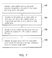
- FIG. 7 is a flowchart of a weight matrix calculation method according to an embodiment of the invention.
- FIG. 8 is a flowchart of a coordinates transformation method according to an embodiment of the invention.
- FIG. 9 is a diagram of an optical touch monitor according to an embodiment of the invention.
- An optical touch control technique is to read the position of a touch object in an image by using multiple optical devices and then transform the position information into screen coordinates through different techniques.
- the optical touch monitor is assumed to be a non-linear system, and a radial basis function (RBF) adapted to both large-scale and small-scale deformations is adopted for coordinates transformation in the optical touch monitor so as to achieve an ideal transformation result.
- the affine transform function used for basic linear transformation is integrated with a non-linear RBF to provide a recapitulative description to non-linear transformation.
- Aforementioned “radial” is a very important concept, and which indicates that each touch position is a radial function and can be changed according to deformations of other surrounding points. Such a characteristic works very well for non-linear transformation.
- a basic non-linear transformation function F(u,v) is expressed as:
- (u, v) represents the coordinates of a touch point
- (u i y i ) represents the coordinates of a control point (CP) i
- c i represents a weight coefficient
- g((u,v),(u i ,v i )) represents the distance between the touch point and the CP i
- N represents the number of CPs
- ⁇ 0 , ⁇ u , and ⁇ v are coefficients of the affine transform function.
- the RBF can be selected from following functions:
- TPS Thin Plate Spline
- TPS function is more adaptable to image registration or coordinates transformation compared to other RBFs.
- TPS function is more adaptable to image registration or coordinates transformation compared to other RBFs.
- following embodiments will be described by taking a TPS function as an example.
- the invention is not limited herein, and other types of TPS functions or other RBFs may also be applied to the invention.
- FIG. 2 illustrates an example of transforming coordinates by using a TPS function as a transformation model according to an embodiment of the invention.
- a TPS function as the transformation model, it is ensured that the calibrated CPs (for example, CPs P 1 and P 2 ) can be correctly transformed between the detected touch position and the actual screen coordinates, and as to those touch points (for example, the touch point P 3 ) other than the CPs, no major error will be produced under the affection of the calibrated CPs P 1 and P 2 , which satisfies the non-linear system assumption.
- FIG. 3 is a diagram of an optical touch monitor according to an embodiment of the invention
- FIG. 4 is a flowchart of an accuracy calibration method according to an embodiment of the invention.
- the accuracy calibration method in the present embodiment is adapted to an optical touch monitor 300 having a first lens 310 and a second lens 320 .
- the first lens 310 and the second lens 320 are disposed at the same side (for example, the upper left and right corners) of the optical touch monitor 300 and faced towards the other side (i.e., the lower two opposite corners) of the optical touch monitor 300 .
- the accuracy calibration method will be described in detail with reference to various components illustrated in FIG. 3 .
- one of a plurality of CPs on the optical touch monitor 300 is touched by using a touch object (step S 402 ). Then, a first image and a second image are respectively captured by using the first lens 310 and the second lens 320 (step S 404 ).
- the CPs can be disposed at specific positions on the optical touch monitor 300 according to the physical characteristics of the optical touch monitor 300 , so as to calibrate a touch position identified on the optical touch monitor 300 .
- FIG. 5A and FIG. 5B are disposition diagrams of control points (CPs) according to an embodiment of the invention.
- FIG. 5A illustrates a disposition example of 5 CPs, wherein the CPs P 1 -P 5 are respectively disposed at the upper left, upper right, bottom left, bottom right, and the center of the central area of the optical touch monitor 500 so as to cover the entire display area of the optical touch monitor 500 .
- FIG. 5A illustrates a disposition example of 5 CPs, wherein the CPs P 1 -P 5 are respectively disposed at the upper left, upper right, bottom left, bottom right, and the center of the central area of the optical touch monitor 500 so as to cover the entire display area of the optical touch monitor 500 .
- FIG. 5A illustrates a disposition example of 5 CPs, wherein the CPs P 1 -P 5 are respectively disposed at the upper left, upper right, bottom left, bottom right, and the center of the central area of the optical touch monitor 500 so as to cover the entire display area of the optical
- 5B illustrates a disposition example of 100 CPs, wherein because the optical touch monitor 500 has such a characteristic that the central area has higher accuracy while the peripheral area has lower accuracy, the optical touch monitor 500 is divided into a peripheral area 510 and a central area 520 for disposing the CPs, so that the density of the CPs distributed within the peripheral area 510 is greater than that of the CPs distributed within the central area 520 and an optimal calibration result can be obtained.
- a first position and a second position of the touch object in the first image and the second image are respectively detected (step S 406 ).
- an image processing for example, rotation, shifting, or shear deformation
- the coordinates of the touch object in the two images are obtained.
- the touch object is detected by using multiple optical devices in an optical system, only the abscissas (i.e., the x-values) of the touch object in the images are desired.
- the x-values of the touch object detected in the second image and the first image are respectively defined as u and v
- the coordinates of the touch object in the image captured by using a camera is defined as p(u,v)
- the transformed coordinates thereof on the optical touch monitor 500 is defined as P(x,y)
- u is the x-value of the touch object in the second image
- v is the x-value of the touch object in the first image.
- FIG. 6A and FIG. 6B illustrate an example of transforming coordinates by using a TPS function as a transformation model according to an embodiment of the invention.
- the width of the first image and the second image captured by the two lenses is 640 pixels, and since only the x-values of the touch object are desired, it is detected in the second image 610 in FIG. 6A that the touch object (herein a finger) is located at the 520 th pixel. Accordingly, the value u in the coordinates p(u,v) of the touch object is set to 520.
- the touch object (herein a finger) is located at the 300 th pixel. Accordingly, the value v in the coordinates p(u,v) of the touch object is set to 300. After that, the two values are combined to obtain the touch position p(u,v) of the touch object as (520,300).
- step S 408 whether there are still undetected CPs is determined after the detection of each CP is completed.
- the touch object is moved to touch other CPs on the optical touch monitor 300 (step S 410 ), and the procedure returns to step S 404 to execute steps S 404 and S 406 again, so as to obtain the first position and the second position of the touch object in the first image and the second image when the touch object touches each of the CPs.
- the non-linear transformation function may include an affine transform function and a RBF, wherein the RBF may be a Gaussian function, a multiquadric function, a polyharmonic spline function, or a TPS function.
- the invention is not limited thereto.
- a TPS function is adopted for system coordinates transformation because the optical touch monitor 300 is a non-linear system.
- the TPS function is defined to be the product of the logarithm of the distance between any two sampling points and the n th power of the distance, wherein n is a positive integer.
- n is a positive integer.
- r is the distance between two CPs or the distance between a touch point and a CP.
- u is the x-value of the touch object in the second image
- v is the x-value of the touch object in the first image
- ⁇ 0 , ⁇ u , and ⁇ v are coefficients of the affine transform function.
- the distance between the coordinates p(u,v) of the touch object and the coordinates p(u c ,v c ) of each CP is calculated.
- the distances are respectively substituted into the TPS function U and multiplied by the corresponding weight coefficients w.
- the sum of the obtained results is the result of the RBF.
- the desired screen coordinates P(x,y) is obtained by adding foregoing sum to the affine transformation function (i.e., ⁇ 0 + ⁇ u + ⁇ v v).
- Y is a spatial position matrix constructed on the screen coordinates P(x,y) of the touch point
- L is a combination of the TPS function K and an image position matrix P constructed on the touch position p(u,v) of the touch object.
- K is a TPS matrix touch object constructed by substituting the distance between the touch position p(u,v) and the coordinates p i (u i ,v i ) of each CP into the TPS function U
- W is a weight matrix of system transformation.
- FIG. 7 is a flowchart of a weight matrix calculation method according to an embodiment of the invention.
- a spatial position transpose matrix Y T is constructed by using the spatial coordinates P(x,y) corresponding to the position of each CP on the optical touch monitor 300 (step S 702 ), which is expressed as:
- n represents the number of CPs.
- step S 704 the first position v and the second position u of each CP are substituted into the affine transform function as image position coordinates, so as to construct an image position matrix P (step S 704 ), which is expressed as:
- (u i ,v i ) is the coordinates obtained by analyzing two images of a first CP captured by the first lens and the second lens
- (u 2 ,v 2 ) is the coordinates obtained by analyzing two images of a second CP captured by the first lens and the second lens
- (u n ,v n ) is the coordinates obtained by analyzing two images of an n th CP captured by the first lens and the second lens.
- step S 706 the distance r between every two CPs is calculated and substituted into the TPS function U, so as to construct a TPS matrix K (step S 706 ), which is expressed as:
- r 12 represents the distance between the first CP P i (u i ,v i ) and the second CP P 2 (u 2 ,v 2 ), and U(r 12 ) is the result obtained by substituting the distance r 12 into the TPS function U.
- U(r 12 ) is the result obtained by substituting the distance r 12 into the TPS function U.
- a matrix L is obtained by filling the TPS matrix K, the image position matrix P, and the transpose matrix P T of the image position matrix P into a matrix having (n+3) columns and (n+3) rows, wherein O is a zero matrix.
- the matrix L is expressed as:
- the weight matrix W can be obtained by substituting foregoing matrixes into the formula (14), and the weight matrix W can be used for transforming a touch position detected on the optical touch monitor 300 into the corresponding screen coordinates.
- step S 410 after obtaining the weight matrix W, when the touch object touches a touch point on the optical touch monitor 300 , the touch position of the touch object on the optical touch monitor 300 is detected, and the touch position is transformed into screen coordinates of the optical touch monitor 300 by using the weight matrix and the non-linear transformation function (step S 414 ).
- the position p(u,v) where the touch object touches the optical touch monitor 300 can be transformed into screen coordinates P(x,y) of the optical touch monitor 300 by using the weight matrix, so as to obtain an accurate transformation result.
- FIG. 8 is a flowchart of a coordinates transformation method according to an embodiment of the invention.
- a first image and a second image are respectively captured by using the first lens 310 and the second lens 320 (step S 802 ), and a first position and a second position of the touch object in the first image and the second image are respectively detected and served as a touch position (step S 804 ).
- the touch position is substituted into an affine transform function as an image position coordinates, so as to construct an image position matrix (step S 806 ), as expressed by foregoing formula (11).
- the distance between the touch point and each CP is calculated and substituted into the TPS function to construct a TPS matrix (step S 808 ), as expressed by foregoing formula (12).
- the image position matrix P, the TPS matrix K, and the weight matrix W are substituted into a non-linear transformation function to transform the touch position into a screen coordinates of the optical touch monitor 300 (step S 810 ).
- the TPS matrix K, the image position matrix P, and the transpose matrix P T of the image position matrix P can be filled into a matrix L, wherein O is a zero matrix.
- the screen coordinates Y transformed from the touch position is obtained by substituting the matrix L and the weight matrix W into foregoing formula (9).
- the spatial coordinates P(x,y) corresponding to these four CPs are respectively:
- the four CPs can be correctly transformed between the image positions p(u,v) and the spatial coordinates P(x,y) through the non-linear transformation technique provided by the invention.
- the accuracy calibration method described in foregoing embodiment is only applicable to a system having two lenses.
- the distance of a touch point cannot be correctly detected when the touch point is located on the line connecting the two lenses.
- the invention provides a solution to resolve this problem.
- the solution is, besides disposing optical lenses at two corners of an upper portion of an optical touch monitor, optical lenses are also disposed at two corners of a lower portion of the optical touch monitor, and position transformations regarding the upper portion and the lower portion of the optical touch monitor are respectively calibrated by using the accuracy calibration method provided by the invention.
- FIG. 9 is a diagram of an optical touch monitor according to an embodiment of the invention.
- a first lens 910 and a second lens 920 are respectively disposed at two corners of the upper portion 92 of the optical touch monitor 900 for detecting and calibrating a touch position of a touch object on the lower portion 94 of the optical touch monitor 900 .
- a third lens 930 and a fourth lens 940 are further disposed at two corners of the lower portion 94 of the optical touch monitor 900 for detecting and calibrating a touch position of the touch object on the upper portion 92 of the optical touch monitor 900 .
- the problem of low accuracy in lens detection can be effectively resolved through the lens disposition described above.
- the invention provides a method for calibrating the accuracy of an optical touch monitor, wherein a touch position detected on the optical touch monitor is transformed by using a non-linear transformation function, and a weight matrix used for the non-linear transformation is calculated and calibrated in advance by using a plurality of CPs, so that the accuracy of the transformation result is improved, and along with the increase in the number of CPs, a transformation result more adapted to the actual situation can be obtained.
Landscapes
- Engineering & Computer Science (AREA)
- General Engineering & Computer Science (AREA)
- Theoretical Computer Science (AREA)
- Human Computer Interaction (AREA)
- Physics & Mathematics (AREA)
- General Physics & Mathematics (AREA)
- Position Input By Displaying (AREA)
- Studio Devices (AREA)
- User Interface Of Digital Computer (AREA)
Abstract
Description
φ(r)=exp(−βr 2), β>0 (2)
φ(r)=√{square root over (r 2+β2)}, β>0 (3)
φ(r)=r k, k=1,3,5, . . . (4)
φ(r)=r k ln(r), k=2,4,6, . . . (5)
φ(r)=±r n ln(r), n=1,2,3, . . . (6)
U=−r ln r (7)
Y=LW (9)
Claims (10)
W=L −1 Y,
Applications Claiming Priority (3)
| Application Number | Priority Date | Filing Date | Title |
|---|---|---|---|
| TW100108517A TWI435250B (en) | 2011-03-14 | 2011-03-14 | Method for calibrating accuracy of optical touch monitor |
| TW100108517 | 2011-03-14 | ||
| TW100108517A | 2011-03-14 |
Publications (2)
| Publication Number | Publication Date |
|---|---|
| US20120235956A1 US20120235956A1 (en) | 2012-09-20 |
| US8907926B2 true US8907926B2 (en) | 2014-12-09 |
Family
ID=46813751
Family Applications (1)
| Application Number | Title | Priority Date | Filing Date |
|---|---|---|---|
| US13/198,727 Expired - Fee Related US8907926B2 (en) | 2011-03-14 | 2011-08-05 | Method for calibrating accuracy of optical touch monitor |
Country Status (3)
| Country | Link |
|---|---|
| US (1) | US8907926B2 (en) |
| CN (1) | CN102681729A (en) |
| TW (1) | TWI435250B (en) |
Families Citing this family (12)
| Publication number | Priority date | Publication date | Assignee | Title |
|---|---|---|---|---|
| TWI442290B (en) | 2012-05-09 | 2014-06-21 | Wistron Corp | Detection system for optical touch control module and automatic detection method thereof |
| CN102929441A (en) * | 2012-09-24 | 2013-02-13 | 杭州再灵电子科技有限公司 | Automatic calibration method for optical touch instrument |
| TWI493399B (en) * | 2012-10-30 | 2015-07-21 | Mstar Semiconductor Inc | Method and associated system for correcting fringing effect of coordinate of touch control |
| TWI470514B (en) * | 2012-11-08 | 2015-01-21 | Wistron Corp | Method of determining whether a lens device is shifted and optical touch system thereof |
| TWI507936B (en) | 2013-02-07 | 2015-11-11 | Mstar Semiconductor Inc | Touch panel and correcting apparatus thereof |
| CN104020869B (en) * | 2013-02-28 | 2017-04-12 | 晨星半导体股份有限公司 | Touch panel and correction device thereof |
| TWI496048B (en) | 2013-07-03 | 2015-08-11 | Wistron Corp | Out-cell optical touch device and related calibrating method |
| US10013595B2 (en) * | 2013-11-28 | 2018-07-03 | Hewlett-Packard Development Company, L.P. | Correlating fingerprints to pointing input device actions |
| CN104679353B (en) * | 2013-11-29 | 2017-08-25 | 纬创资通股份有限公司 | Optical touch device and calculation method of touch point coordinates |
| TWI536221B (en) * | 2014-10-17 | 2016-06-01 | 緯創資通股份有限公司 | Optical touch apparatus and coordinate correction method thereof |
| CN104571729A (en) * | 2015-01-14 | 2015-04-29 | 东南大学 | Multiple contact identification method applied to optical touch screen |
| CN115729379A (en) * | 2021-08-26 | 2023-03-03 | 北京科加触控技术有限公司 | Optical touch panel surface calibration method and device |
Citations (5)
| Publication number | Priority date | Publication date | Assignee | Title |
|---|---|---|---|---|
| US20090161945A1 (en) * | 2007-12-21 | 2009-06-25 | Canon Kabushiki Kaisha | Geometric parameter measurement of an imaging device |
| US20110050640A1 (en) * | 2009-09-03 | 2011-03-03 | Niklas Lundback | Calibration for a Large Scale Multi-User, Multi-Touch System |
| US20110122093A1 (en) * | 2009-11-20 | 2011-05-26 | Samsung Electronics Co., Ltd. | Display apparatus and method for calibrating a touch system |
| US20120057053A1 (en) * | 2007-06-26 | 2012-03-08 | Airbus Opertations (S.A.S) | Method for high precision lens distortion calibration and removal |
| US20120133616A1 (en) * | 2010-11-29 | 2012-05-31 | Nishihara H Keith | Creative design systems and methods |
Family Cites Families (3)
| Publication number | Priority date | Publication date | Assignee | Title |
|---|---|---|---|---|
| US6531999B1 (en) * | 2000-07-13 | 2003-03-11 | Koninklijke Philips Electronics N.V. | Pointing direction calibration in video conferencing and other camera-based system applications |
| CN100462937C (en) * | 2005-10-09 | 2009-02-18 | 深圳市巨龙科教高技术股份有限公司 | Computer projection auxiliary positioning method and interactive demonstration system using said method |
| CN101697105B (en) * | 2009-10-26 | 2011-09-14 | 广东威创视讯科技股份有限公司 | Camera type touch detection positioning method and camera type touch detection system |
-
2011
- 2011-03-14 TW TW100108517A patent/TWI435250B/en not_active IP Right Cessation
- 2011-03-22 CN CN2011100692564A patent/CN102681729A/en active Pending
- 2011-08-05 US US13/198,727 patent/US8907926B2/en not_active Expired - Fee Related
Patent Citations (5)
| Publication number | Priority date | Publication date | Assignee | Title |
|---|---|---|---|---|
| US20120057053A1 (en) * | 2007-06-26 | 2012-03-08 | Airbus Opertations (S.A.S) | Method for high precision lens distortion calibration and removal |
| US20090161945A1 (en) * | 2007-12-21 | 2009-06-25 | Canon Kabushiki Kaisha | Geometric parameter measurement of an imaging device |
| US20110050640A1 (en) * | 2009-09-03 | 2011-03-03 | Niklas Lundback | Calibration for a Large Scale Multi-User, Multi-Touch System |
| US20110122093A1 (en) * | 2009-11-20 | 2011-05-26 | Samsung Electronics Co., Ltd. | Display apparatus and method for calibrating a touch system |
| US20120133616A1 (en) * | 2010-11-29 | 2012-05-31 | Nishihara H Keith | Creative design systems and methods |
Non-Patent Citations (5)
| Title |
|---|
| Arad et al., "Image Warping Using few Anchor Points and Radial Functions", CVGIP: Graphical Models and Image Processing 56 (1994) p. 1-p. 12. |
| Ardeshir Goshtasby, "Registration of Images With Geometric Distortions", IEEE Transactions on Geoscience and Remote Sensing, vol. 26, No. 1, Jan. 1998, p. 60-p. 64. |
| David N. Fogel, "Image rectification with radial basis functions: Application to RS/GIS data integration", Proceedings of the Third International Conference on Integrating GIS and Environmental Modelling, Santa Fe, New Mexico, 1996, p. 1-p. 28. |
| Wiemker et al., "Application of Elastic Registration to Imaginery From Airborne Scanners", International Archives for Photogrammetry and Remote Sensing XXXI, Part B, Commission IV (1996) p. 1-p. 6. |
| Zitova et al., "Image registration methods: a survey", Image and Vision Computing 21 (2003) p. 977-p. 1000. |
Also Published As
| Publication number | Publication date |
|---|---|
| CN102681729A (en) | 2012-09-19 |
| US20120235956A1 (en) | 2012-09-20 |
| TW201237712A (en) | 2012-09-16 |
| TWI435250B (en) | 2014-04-21 |
Similar Documents
| Publication | Publication Date | Title |
|---|---|---|
| US8907926B2 (en) | Method for calibrating accuracy of optical touch monitor | |
| CN104048674B (en) | It is calibrated using the NI Vision Builder for Automated Inspection of inaccurate alignment target | |
| US9024916B2 (en) | Extracting touch data that represents one or more objects on a touch surface | |
| JP6228300B2 (en) | Improving the resolution of plenoptic cameras | |
| US10417750B2 (en) | Image processing method, device and photographic apparatus | |
| US8914254B2 (en) | Latency measurement | |
| US8749530B2 (en) | Optical touch display, a calibration apparatus and a calibration method thereof | |
| US20090146972A1 (en) | Apparatus and method for detecting a pointer relative to a touch surface | |
| CN113284083A (en) | Method and system for performing automatic camera calibration | |
| JP2003065716A (en) | Touch system and calibrating method and medium of the same, and method for determining position of object relative to reference frame using triangular surveying from grasped object image | |
| CN110196422B (en) | Laser ranging test method, test device and mobile terminal | |
| US8400429B2 (en) | Touch device and touch method | |
| US20160334937A1 (en) | Optical touch device and sensing method thereof | |
| CN113436272B (en) | Underwater stereo vision system spherical refraction correction method, electronic equipment | |
| CN114897997B (en) | Camera calibration method, device, equipment and storage medium | |
| US9116574B2 (en) | Optical touch device and gesture detecting method thereof | |
| US9569036B2 (en) | Multi-touch system and method for processing multi-touch signal | |
| CN111145268B (en) | A video registration method and device | |
| US9983685B2 (en) | Electronic apparatuses and methods for providing a man-machine interface (MMI) | |
| US8218004B2 (en) | Displacement sensing system | |
| US8724090B2 (en) | Position estimation system | |
| CN118485620A (en) | Calibration method and device of screen model, electronic equipment and storage medium | |
| CN117135477A (en) | Data fusion methods, devices, electronic devices and storage media in sensors | |
| CN111862051A (en) | Method and system for performing automatic camera calibration | |
| CN106293263A (en) | Optical sensing electronic device and optical sensing method |
Legal Events
| Date | Code | Title | Description |
|---|---|---|---|
| AS | Assignment |
Owner name: WISTRON CORPORATION, TAIWAN Free format text: ASSIGNMENT OF ASSIGNORS INTEREST;ASSIGNOR:WANG, CHUN-WEI;REEL/FRAME:026712/0311 Effective date: 20110805 |
|
| STCF | Information on status: patent grant |
Free format text: PATENTED CASE |
|
| MAFP | Maintenance fee payment |
Free format text: PAYMENT OF MAINTENANCE FEE, 4TH YEAR, LARGE ENTITY (ORIGINAL EVENT CODE: M1551) Year of fee payment: 4 |
|
| FEPP | Fee payment procedure |
Free format text: MAINTENANCE FEE REMINDER MAILED (ORIGINAL EVENT CODE: REM.); ENTITY STATUS OF PATENT OWNER: LARGE ENTITY |
|
| LAPS | Lapse for failure to pay maintenance fees |
Free format text: PATENT EXPIRED FOR FAILURE TO PAY MAINTENANCE FEES (ORIGINAL EVENT CODE: EXP.); ENTITY STATUS OF PATENT OWNER: LARGE ENTITY |
|
| STCH | Information on status: patent discontinuation |
Free format text: PATENT EXPIRED DUE TO NONPAYMENT OF MAINTENANCE FEES UNDER 37 CFR 1.362 |
|
| FP | Lapsed due to failure to pay maintenance fee |
Effective date: 20221209 |