US8907760B2 - Multiple-frequency solutions for remote access systems - Google Patents
Multiple-frequency solutions for remote access systems Download PDFInfo
- Publication number
- US8907760B2 US8907760B2 US12/878,349 US87834910A US8907760B2 US 8907760 B2 US8907760 B2 US 8907760B2 US 87834910 A US87834910 A US 87834910A US 8907760 B2 US8907760 B2 US 8907760B2
- Authority
- US
- United States
- Prior art keywords
- coil
- antenna
- windings
- coil antenna
- signal
- Prior art date
- Legal status (The legal status is an assumption and is not a legal conclusion. Google has not performed a legal analysis and makes no representation as to the accuracy of the status listed.)
- Active, expires
Links
Images


Classifications
-
- H—ELECTRICITY
- H01—ELECTRIC ELEMENTS
- H01Q—ANTENNAS, i.e. RADIO AERIALS
- H01Q1/00—Details of, or arrangements associated with, antennas
- H01Q1/27—Adaptation for use in or on movable bodies
- H01Q1/32—Adaptation for use in or on road or rail vehicles
- H01Q1/3208—Adaptation for use in or on road or rail vehicles characterised by the application wherein the antenna is used
- H01Q1/3233—Adaptation for use in or on road or rail vehicles characterised by the application wherein the antenna is used particular used as part of a sensor or in a security system, e.g. for automotive radar, navigation systems
- H01Q1/3241—Adaptation for use in or on road or rail vehicles characterised by the application wherein the antenna is used particular used as part of a sensor or in a security system, e.g. for automotive radar, navigation systems particular used in keyless entry systems
-
- G—PHYSICS
- G06—COMPUTING OR CALCULATING; COUNTING
- G06K—GRAPHICAL DATA READING; PRESENTATION OF DATA; RECORD CARRIERS; HANDLING RECORD CARRIERS
- G06K19/00—Record carriers for use with machines and with at least a part designed to carry digital markings
- G06K19/06—Record carriers for use with machines and with at least a part designed to carry digital markings characterised by the kind of the digital marking, e.g. shape, nature, code
- G06K19/067—Record carriers with conductive marks, printed circuits or semiconductor circuit elements, e.g. credit or identity cards also with resonating or responding marks without active components
- G06K19/07—Record carriers with conductive marks, printed circuits or semiconductor circuit elements, e.g. credit or identity cards also with resonating or responding marks without active components with integrated circuit chips
- G06K19/077—Constructional details, e.g. mounting of circuits in the carrier
- G06K19/07749—Constructional details, e.g. mounting of circuits in the carrier the record carrier being capable of non-contact communication, e.g. constructional details of the antenna of a non-contact smart card
- G06K19/07766—Constructional details, e.g. mounting of circuits in the carrier the record carrier being capable of non-contact communication, e.g. constructional details of the antenna of a non-contact smart card comprising at least a second communication arrangement in addition to a first non-contact communication arrangement
- G06K19/07767—Constructional details, e.g. mounting of circuits in the carrier the record carrier being capable of non-contact communication, e.g. constructional details of the antenna of a non-contact smart card comprising at least a second communication arrangement in addition to a first non-contact communication arrangement the first and second communication means being two different antennas types, e.g. dipole and coil type, or two antennas of the same kind but operating at different frequencies
-
- G—PHYSICS
- G06—COMPUTING OR CALCULATING; COUNTING
- G06K—GRAPHICAL DATA READING; PRESENTATION OF DATA; RECORD CARRIERS; HANDLING RECORD CARRIERS
- G06K19/00—Record carriers for use with machines and with at least a part designed to carry digital markings
- G06K19/06—Record carriers for use with machines and with at least a part designed to carry digital markings characterised by the kind of the digital marking, e.g. shape, nature, code
- G06K19/067—Record carriers with conductive marks, printed circuits or semiconductor circuit elements, e.g. credit or identity cards also with resonating or responding marks without active components
- G06K19/07—Record carriers with conductive marks, printed circuits or semiconductor circuit elements, e.g. credit or identity cards also with resonating or responding marks without active components with integrated circuit chips
- G06K19/077—Constructional details, e.g. mounting of circuits in the carrier
- G06K19/07749—Constructional details, e.g. mounting of circuits in the carrier the record carrier being capable of non-contact communication, e.g. constructional details of the antenna of a non-contact smart card
- G06K19/07773—Antenna details
- G06K19/07792—Antenna details the antenna adapted for extending in three dimensions
-
- H—ELECTRICITY
- H01—ELECTRIC ELEMENTS
- H01Q—ANTENNAS, i.e. RADIO AERIALS
- H01Q25/00—Antennas or antenna systems providing at least two radiating patterns
-
- H01Q5/0048—
-
- H—ELECTRICITY
- H01—ELECTRIC ELEMENTS
- H01Q—ANTENNAS, i.e. RADIO AERIALS
- H01Q5/00—Arrangements for simultaneous operation of antennas on two or more different wavebands, e.g. dual-band or multi-band arrangements
- H01Q5/30—Arrangements for providing operation on different wavebands
- H01Q5/307—Individual or coupled radiating elements, each element being fed in an unspecified way
- H01Q5/342—Individual or coupled radiating elements, each element being fed in an unspecified way for different propagation modes
- H01Q5/35—Individual or coupled radiating elements, each element being fed in an unspecified way for different propagation modes using two or more simultaneously fed points
-
- H—ELECTRICITY
- H01—ELECTRIC ELEMENTS
- H01Q—ANTENNAS, i.e. RADIO AERIALS
- H01Q7/00—Loop antennas with a substantially uniform current distribution around the loop and having a directional radiation pattern in a plane perpendicular to the plane of the loop
Definitions
- Remote access systems provide individuals with a convenient and secure access to, for example, vehicles or buildings.
- a particular type of remote access system involves the use of a base station at the vehicle or building and a portable device, carried by an individual.
- the base station and portable device can be configured with varying levels of security protocols and additional functionality. This additional security or functionality, however, may result in the portable device having increased size, costs and/or power consumption.
- remote access systems e.g., for the automotive industry
- the remote access system can be used to unlock vehicle doors, start vehicle engines, open trunks, turn on/off lights and/or various other functions.
- a particular remote access system is a Passive Keyless Entry (PKE) system.
- PKE systems can use, for example, three-dimensional low-frequency (3D LF) antennas.
- 3D LF antennas in the PKE key allows for the PKE key to perform a rotation-independent detection of a wakeup sequence, which can be transmitted from a base station in the vehicle.
- the PKE key can also measure the field strength of signal(s) transmitted from the vehicle, which can be used to establish the spatial position of the PKE key within the magnetic field caused by the transmitted signal(s). Additional antennas associated with other functionalities, however, can adversely affect the size of the PKE key and are therefore often avoided.
- an ISO 14443 compliant interface e.g., a 13.56 MHz carrier frequency
- the use of an ISO 14443 compliant interface in the key generally requires a larger key due to, for example, the additional PCB space necessary to place a high frequency (HF) antenna.
- Certain embodiments of the present disclosure are directed to a communication circuit including a printed circuit board (PCB) and a three-dimensional radio antenna connected to the PCB for receiving a radio frequency signal.
- the three dimensions include planes X, Y, and Z.
- the three-dimensional radio antenna includes a first coil oriented in the X plane, a second coil oriented in the Y plane and a third coil oriented in the Z plane.
- the circuit includes a first communication circuit on the PCB and for communicating a low frequency (LF) signal with a carrier frequency that is between 30 kHz and 300 kHz.
- the first communication circuit includes one or more processing circuits configured to code communications carried by the LF signal.
- a first electrical connection provides an LF signal communications path between one or more processing circuit(s) and the first coil.
- a second electrical connection provides an LF signal communication path between the one or more processing circuit(s) and the second coil.
- a third electrical connection provides an LF signal communication path between the one or more processing circuit(s) and the third
- Certain embodiments of the present disclosure are directed to a multipurpose antenna assembly including a package that includes a first coil antenna oriented in an X plane and configured to receive an LF signal having a carrier frequency between 30 kHz and 300 kHz.
- a second coil antenna is oriented in a Y plane and configured to receive an LF signal having a carrier frequency between 30 kHz and 300 kHz.
- a third coil antenna is oriented in the Z plane and configured to receive an LF signal having a carrier frequency between 30 kHz and 300 kHz.
- a fourth coil antenna is oriented in the Z plane and configured to produce a high frequency (HF) signal having a carrier frequency between 3 MHz and 30 MHz.
- HF high frequency
- FIG. 1 depicts an antenna package with several coil antennas, consistent with an embodiment of the present disclosure
- FIG. 2 depicts an antenna package with several coil antennas and a coil tap, consistent with an embodiment of the present disclosure
- FIG. 3 depicts a communication system consistent with an embodiment of the present disclosure
- FIG. 4 depicts a 3D antenna package with a tap on one of the coil antennas, consistent with embodiments of the present disclosure
- FIG. 5 depicts a 3D antenna package with an additional HF-frequency coil antenna surrounding one of the 3D coil antennas, consistent with embodiments of the present disclosure
- FIG. 6 depicts a 3D antenna package with an additional HF-frequency coil antenna below one of the 3D coil antennas, consistent with embodiments of the present disclosure.
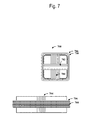
- FIG. 7 depicts a 3D antenna package with an additional HF-frequency coil antenna alternating with one of the 3D coil antennas, consistent with embodiments of the present disclosure.
- the present disclosure is believed to be useful in a system in which a three-dimensional low-frequency (3D-LF) antenna and a high frequency (HF) antenna are used.
- Applications include, for example, passive keyless entry (PKE) systems in the automotive industry. While the present disclosure is not necessarily limited to such applications, various aspects of the disclosure may be appreciated through a discussion of various examples using these contexts.
- a key fob is used as part of a PKE system that provides functionality, such as remote car starting or remote keyless entry functions (e.g., unlocking of the vehicle and/or opening the trunk of a car).
- the key fob is configured to provide a variety of different features that are facilitated by the use of multiple wireless communication protocols and frequencies. These different communication protocols can require different antenna properties.
- a PKE system can include a key fob with each of an ultra high frequency (UHF) antenna (between 300 MHz and 3 GHz), a 3D LF antenna (between 30 kHz and 300 kHz) and an HF antenna (between 3 MHz and 30 MHz).
- UHF ultra high frequency
- Embodiments of the present disclosure are directed toward integration of two or more of such antennas into a single package. This can be particularly useful for reducing the PCB footprint, the key fob size and/or improving the receiving properties of the antenna (e.g., due to short PCB trace routes).
- a particular embodiment of the present disclosure is directed toward a system that determines the location of a key fob using measurements from a 3D LF antenna.
- a base station transmits an LF signal that is detected by the key fob using the 3D LF antenna.
- the strength of the LF signal is used to determine the location of the fob with respect to the base station.
- the use of a 3D LF antenna allows for the key fob to detect LF signal of the base station regardless of the key fob's physical orientation. This is necessary because the LF antennas have a directional component that results in significantly attenuated signal strength when the antenna is not properly orientated with the transmitted LF signal.
- the base station includes multiple LF transmitters.
- the signal strength for each of the LF transmitters can be determined to ascertain the specific location of the fob in relation to the transmitters. This is facilitated by the use of a 3D-LF antenna that can receive signals from any direction and thereby receive signals from each of the LF transmitters simultaneously.
- the PKE system can use such a determined location as part of a conditional check for the performance of various actions or functions. For example, the PKE system can prevent a vehicle door from being unlocked unless an associated fob is within 10 feet of the vehicle door.
- the PKE system can also perform various other functions based on the key fob location. For example, a car's headlights can be turned on as soon as the associated key fob comes within a first range (e.g., 20 feet from the car), and the car can unlock when the fob is within a second range (e.g., 10 feet from the car).
- the PKE system can also determine if the key is inside the car. This determination can be used to ensure that the key fob is not locked inside the car or that the car is not started unless the key fob is inside the car.
- a key fob includes an LF antenna transceiver circuit and a wakeup pattern detector.
- the key fob can also include a UHF antenna transceiver circuit that is activated in response to the LF antenna circuit receiving a specific wakeup pattern.
- the UHF antenna transceiver circuit is enabled for communication with the base station.
- the UHF antenna circuit can be used to communicate security or other identifying information between the key fob and the base station.
- An HF antenna circuit can also be enabled in response to a wakeup pattern received by the 3D LF antenna circuit.
- the key fob can be configured so that an HF antenna circuit actively listens for a wakeup pattern that is transmitted using an HF frequency.
- the UHF antenna of the key fob and a UHF antenna on the base station are used to transmit data that functions as a security check to ensure that the key fob and base station match (e.g., both the key fob and base station have matching security codes).
- the key fob can send predetermined signals to the base station corresponding to requests for various functions to be performed, e.g., unlocking or starting of the vehicle.
- the PKE system includes a first base station that includes an LF frequency transceiver circuit and a second base station that transmits on an HF frequency transceiver circuit.
- the two base stations can be located in physically distinct locations relative to one another.
- the first base station can be located within a vehicle, while the second base station is located within a garage, e.g., as part of a wireless garage door opening system.
- a portable device is configured to communicate using a wireless protocol that is in compliance with ISO 14443 standards.
- This ISO 14443 standard is implemented using an HF antenna that is located within the same antenna package as a 3D LF antenna. This can be particularly useful for space saving (e.g., allowing for a small key fob) while allowing for communications both with a base station transmitting using an LF carrier frequency and a base station transmitting on an HF carrier frequency and protocol complying with ISO 14443.
- This can also be particularly useful for providing a high quality antenna solution, e.g., relative to a PCB antenna solution.
- FIG. 1 an antenna package 100 consistent with an embodiment of the present disclosure is depicted.
- the package includes three LF directional coil antennas ( 102 , 104 , 106 ).
- the three coils when oriented correctly, form a 3D-LF antenna.
- the coils are each oriented relative to X, Y and Z axes that define a Cartesian coordinate system for a three-dimensional space.
- antenna 102 is a coil antenna oriented along the X-Axis
- antenna 104 is a coil antenna oriented along the Y-Axis
- antenna 106 is a coil antenna oriented along the Z-Axis.
- each of the coil antennas is oriented parallel to a respective X, Y or Z plane, consistent with the Cartesian coordinate system.
- Antennas 102 , 104 and 106 are designed for communications using carrier frequencies between 30 kHz and 300 kHz. In certain more specific embodiments antennas 102 , 104 and 106 are designed for use with a carrier frequency of 125 kHz.
- Package 100 includes a fourth antenna 108 that is oriented along the Z-Axis. Antenna 108 is designed for communications that use a carrier frequency of between 3 MHz and 30 MHz. In certain embodiments of the present disclosure, antenna 108 is designed for a carrier frequency that is 13.56 MHz.
- an antenna is designed for a particular carrier frequency by setting the reactance of the antenna according to the desired frequency.
- This reactance can be determined through the inductance and/or capacitance of the antenna.
- a coil antenna has an inductance value that corresponds to the number of windings in the coil, the type of core, the type of conductor used for the windings and other factors.
- the core can be air or a magnetic material such as ferrite, for example.
- the inductance for the LF coil antennas discussed herein is on the order of millihenries.
- the inductance of the LF antennas can be in the range of 1-8 mH for use with a carrier frequency of around 125 kHz.
- the HF coil antennas discussed herein have a lower inductance than the LF antennas.
- the inductance of the HF coil antenna can be on the order of microhenries.
- the inductance of the HF coil antenna can be in the range of 1.5-6.0 ⁇ H for use with a carrier frequency of about 13.56 MHz.
- the difference in inductance between the LF antennas and the HF antennas can be due to the smaller number of windings associated with the HF antenna relative to the number of windings of the LF antenna.
- a specific position of a portable device is determined by measuring the field strength of a magnetic field using signals received from directional coils of a 3D LF antenna within the package 100 .
- PKE Passive Keyless Entry
- the PKE is used in connection with a vehicle. Determining that location of the portable PKE element that includes the antenna package can be useful to ensure a user is not locked out of the car, for example. Determining the location of the package can also be used to ensure that package 100 is within a specified distance before unlocking the car or popping the trunk, as further examples.
- the antenna package is designed for placement on a PCB.
- package types include a through-hole package, a surface mount package or a custom designed package.
- custom designed packages can range in size from about 5 mm ⁇ 5 mm to about 20 mm ⁇ 20 mm with a height (i.e., perpendicular to the PCB upon placement of around 2-10 mm).
- the length and width dimensions of the package do not need to be equal.
- An example package can have dimensions of 11 mm ⁇ 13 mm ⁇ 5 mm.
- the package size can be around 15 mm ⁇ 15 mm with a height (i.e., perpendicular to the PCB upon placement) of around 5 mm.
- Non-limiting examples of surface mount packages include dual in-line packages (e.g., small-outline integrated circuit (SOIC) and shrink small-outline package (SSOP)), quad in-line packages (e.g., plastic leaded chip carrier (PLCC) and quad flat package (QFP)) and grid array packages (e.g., pin grid array (PGA) and ball grid array (BGA)).
- SOIC small-outline integrated circuit
- SSOP shrink small-outline package
- quad in-line packages e.g., plastic leaded chip carrier (PLCC) and quad flat package (QFP)
- grid array packages e.g., pin grid array (PGA) and ball grid array (BGA)
- the sizes and package times discussed herein are merely illustrative of a few possible package sizes and can be adjusted depending upon the particular application and/or configuration of the coil antennas.
- the PCB footprint for the packages can be configured as desired, e.g., to include sufficient connections for use as both a 3D-LF antenna and an
- FIG. 2 depicts an antenna package with several coil antennas and a coil tap, consistent with an embodiment of the present disclosure.
- the antenna package 200 includes a 3D LF antenna that includes coil antenna 202 aligned on the X-axis, coil antenna 204 aligned on the Y-axis and coil antenna 206 aligned on the Z-axis.
- the LF coil antennas 202 , 204 , and 206 are designed for use with LF communications having a carrier frequency that is between 30 kHz to 300 kHz. In certain embodiments of the present disclosure, the carrier frequency is 125 kHz.
- Coil antenna 206 includes a tap 210 that is connected at a location between ends of windings of the coil antenna 206 .
- a transceiver circuit can use fewer than all of the windings of coil antenna 206 .
- a portion 208 of coil antenna 206 can be used as an HF antenna that is designed for use with a carrier frequency between 3 MHz and 30 MHz.
- the carrier frequency is 13.56 MHz. This allows for the effective inductance between one of the endpoints of coil antenna 206 and the tap 210 to be significantly less than the effective inductance between both coil endpoints of coil antenna 206 .
- tap 210 can be placed so that portion 208 includes approximately ten percent of the coils relative to the number of coils of the entire coil antenna 206 , which is approximately consistent with the ratio that could be used for an LF carrier frequency of 125 kHz and an HF carrier frequency of 13.56 MHz
- FIG. 3 depicts a communication system consistent with an embodiment of the present invention.
- a portable device 310 is configured to communicate with base stations 312 and 314 using an antenna package 300 that includes 3 LF coil antennas, 302 , 304 and 306 . Each of the antennas is oriented along a different axis.
- the LF coil antennas 302 , 304 and 306 are antenna coupled to an inductive receiver 316 .
- the inductive receiver 316 is a three-dimensional receiver that is configured to receive wireless signals using coil antennas 302 , 304 and 306 .
- the inductive receiver 316 can be configured to respond to an LF wakeup signal. For instance, wakeup pattern detector 324 determines whether the desired wake up pattern has been received.
- the use of a wakeup pattern allows for a portable device 310 to conserve energy by only enabling circuit components (e.g., an HF receiver or tag) in the presence of a base station.
- the wakeup signal can include an identifier that is unique to the specific portable device.
- Inductive transmitter 326 can be used to transmit the wake up signal.
- the use of the LF receiver and the 3D antenna in particular allows for the wake up signal to activate portions of portable device 310 only when it is within a prescribed area near the base station 312 transmitting the signal.
- Antenna package 300 and inductive receiver 316 receive signals, including the wakeup signal, from inductive transmitter and antenna 326 .
- the portable device 310 can conserve power by disabling various circuit components, such as microcontroller 318 , UHF-transmitter 320 and/or HF tag or receiver 332 . These circuit components can then be enabled in response to the receipt of a wakeup signal.
- the microcontroller 318 can be used to generate an authentication signal that UHF transmitter 320 can communicate to base station 312 .
- Base station 312 can use the received authentication signal to verify that the portable device 310 has a valid identifier.
- the information sent to UHF-receiver 322 can also include information regarding the location of portable device 310 with respect to the base station 312 .
- Microcontroller 330 processes the received signals and determines the actions to take. For example, if portable device 310 is a PKE key fob for a vehicle, then after authentication of the key fob, a signal can be sent from the base station to unlock the doors of the vehicle.
- the portable device 310 can also include an additional HF coil antenna 308 , and associated reader 332 .
- the additional HF coil antenna 308 can be used to effect communications with a second base station 314 . This can be used, for example, to provide a single fob for opening a garage door as well as unlocking a vehicle.
- FIG. 4 illustrates various ways in which the additional HF coil antenna can be implemented within a single antenna package consistent with embodiments of the present disclosure.
- Each of the figures includes views of the package from the top and from the side.
- FIGS. 4-7 illustrates the additional HF coil antenna being oriented along the Z-axis; however, embodiments of the present disclosure can also be implemented with the HF coil oriented along or parallel to the X-axis or the Y-axis.
- This HF antenna is configured to be used in connection with an HF signal between 3 MHz and 30 MHz.
- the antenna package also includes a 3D LF antenna that includes three coil antennas oriented relative to or parallel to respective ones of the X, Y and Z axes.
- the LF coil antennas can be configured for an LF signal of between 3 kHz and 300 kHz.
- the HF antenna 508 is configured for use with a carrier frequency of 13.56 MHz and the LF coil antennas is configure for use with a carrier frequency of 125 kHz.
- FIG. 4 depicts both the top and side views of an antenna package 400 with coil antenna 402 on the X-axis, coil antenna 404 on the Y-Axis, and coil 406 on the Z-axis.
- Coil antenna 406 includes a tap 410 .
- the tap is located at a point along the coil of antenna 406 to allow for the coil antenna 406 to be used for both LF and HF carrier frequencies.
- an LF transceiver circuit can be connected across the entire coil length of the coil antenna 406
- the HF transceiver circuit can be connected across the tap and one end of coil antenna 406 .
- the HF transceiver sees a lower effective inductance than the LF transceiver circuit, as would be consistent with the respective frequencies thereof.
- the LF carrier frequency can be 125 kHz while the HF carrier frequency can be 13.56 MHz.
- FIG. 5 depicts both the top and side views of an antenna package 500 including LF coil antennas 502 on the X-axis, 504 on the Y-axis, and 506 on the Z-axis.
- the antenna package 500 also includes a fourth coil antenna 508 which is wrapped around the outside of coil antenna 506 on the Z axis as illustrated.
- the antenna package can be constructed using a coil antenna 506 that has a number of windings that is consistent with the desired LF carrier frequency. Thereafter, coil antenna 508 can be constructed by winding the coil antenna 508 around the outside of coil 506 and using a number of windings that is consistent with the desired HF carrier frequency.
- an embodiment of the present disclosure is directed toward an antenna package in which the LF coil antenna 506 is swapped with the HF coil antenna 508 .
- the windings of LF coil antenna 506 are wrapped around the windings of the HF coil antenna 508 .
- FIG. 6 depicts both the top and side views of an antenna package 600 including both LF coil antennas and an HF coil antenna 608 .
- the package 600 includes coil antenna 602 in the X direction, coil antenna 604 in the Y direction and coil antenna 606 in the Z direction. Consistent with one embodiment of the present disclosure, the HF coil antenna 608 is below (e.g., nearer to the PCB connection points) antenna 606 when the package 600 is viewed from the side and is depicted with the dashed lines.
- the two coil antennas 606 and 608 can be wound simultaneously, or one after the other depending upon the desired manufacturing process.
- the antenna package can be constructed using a coil antenna 606 that has a number of windings that is consistent with the desired LF carrier frequency.
- Coil antenna 608 can be constructed below coil 606 using a number of windings that is consistent with the desired HF carrier frequency. In an alternative embodiment, not shown, coil antenna 608 can be constructed above coil 606 using a number of windings that is consistent with the desired HF carrier frequency.
- FIG. 7 depicts both the top and side views of an antenna package 700 including three LF coil antennas and an HF coil antenna 708 .
- LF coil antenna 702 is located on the X-axis
- LF coil antenna 704 is located on the Y-axis
- LF coil antenna 706 is located on the Z axis.
- FIG. 7 depicts and embodiment in which the windings of HF antenna 708 and LF coil antenna 706 alternate when the antenna package 700 is viewed from the side. As the LF coil antenna 706 will include more windings than the HF coil antenna 708 , the windings do not necessarily alternate the entire length of the Z axis.
- the antenna package can be constructed by winding two coils at the same time, one for coil antenna 706 and the other for coil antenna 708 . This can be particularly useful for reducing manufacturing time and costs.
- the length of the LF coil wire and the HF coil wire corresponds to a number of windings that is consistent with the desired carrier frequencies.
- the windings are intermixed, such that, for example, there are two or more windings associated with the LF antenna between every one winding for the HF antenna.
- the disclosure contemplates a variety of intermixed embodiments.
- Embodiments of the present disclosure relate to the use of a common coil antenna for communications using both HF and LF carrier frequencies. This includes, for instance, the use of a coil antenna having a tap that allows an HF transceiver circuit to be connected across less than all of the windings of the coil antenna and an LF transceiver circuit to be connected across all of the windings of the coil antenna.
- Various embodiments of the present disclosure relate to the configuration and design of the transceiver circuits to accommodate this shared usage.
- One such embodiment relates to filtering of received signals by the transceiver circuits, e.g., to attenuate signals outside of the desired frequency range. In many applications, such filtering is sufficient even for embodiments in which coil antenna windings are shared between two transceiver circuits.
- an isolation circuit to electrically isolate the transceiver circuits from the coil antenna. This can be useful as the transceiver circuits may be adversely affected by external (relative to the antennas) capacitances added by the other transceiver circuit. Accordingly, one or more of the transceiver circuits can include a switch that isolates the transceiver circuit from the antenna when not in use. Thus, the LF transceiver circuit can be isolated from the coil antenna when the HF transceiver circuit is active and vice versa. For PKE-based systems, this can be particularly effective because the communications for each of the transceiver circuits can be implemented at a distinct time.
- the HF transceiver circuit can be isolated from the coil antenna while the LF transceiver circuit is actively listening for a wakeup pattern. Once the wakeup pattern is detected, the LF transceiver circuit can be isolated to allow the HF transceiver circuit to communicate with a base station. Thereafter, the HF transceiver circuit can be isolated.
- an active filtering can be implemented between the transceiver circuits. For instance, knowledge of the signal received by each transceiver circuit can be provided to the other transceiver circuit. This information can then be used to actively filter out such unwanted signals. This can be particularly useful for applications that use digital filtering.
- transceiver circuit uses the term transceiver circuit to denote a communication circuit that can be used as a receiver or a transmitter. Unless otherwise stated, the transceiver circuits discussed herein can also be implemented as a receive-only circuit or a transmit-only circuit.
- HF antenna can be implemented on X, Y or Z axis.
Landscapes
- Engineering & Computer Science (AREA)
- Computer Hardware Design (AREA)
- Microelectronics & Electronic Packaging (AREA)
- Physics & Mathematics (AREA)
- General Physics & Mathematics (AREA)
- Theoretical Computer Science (AREA)
- Computer Security & Cryptography (AREA)
- Radar, Positioning & Navigation (AREA)
- Remote Sensing (AREA)
- Computer Networks & Wireless Communication (AREA)
- Near-Field Transmission Systems (AREA)
- Lock And Its Accessories (AREA)
Abstract
Description
Claims (20)
Priority Applications (2)
| Application Number | Priority Date | Filing Date | Title |
|---|---|---|---|
| US12/878,349 US8907760B2 (en) | 2010-09-09 | 2010-09-09 | Multiple-frequency solutions for remote access systems |
| EP11180550.3A EP2429033B1 (en) | 2010-09-09 | 2011-09-08 | Multiple-frequency solutions for remote access system |
Applications Claiming Priority (1)
| Application Number | Priority Date | Filing Date | Title |
|---|---|---|---|
| US12/878,349 US8907760B2 (en) | 2010-09-09 | 2010-09-09 | Multiple-frequency solutions for remote access systems |
Publications (2)
| Publication Number | Publication Date |
|---|---|
| US20120062358A1 US20120062358A1 (en) | 2012-03-15 |
| US8907760B2 true US8907760B2 (en) | 2014-12-09 |
Family
ID=44674464
Family Applications (1)
| Application Number | Title | Priority Date | Filing Date |
|---|---|---|---|
| US12/878,349 Active 2032-02-10 US8907760B2 (en) | 2010-09-09 | 2010-09-09 | Multiple-frequency solutions for remote access systems |
Country Status (2)
| Country | Link |
|---|---|
| US (1) | US8907760B2 (en) |
| EP (1) | EP2429033B1 (en) |
Cited By (6)
| Publication number | Priority date | Publication date | Assignee | Title |
|---|---|---|---|---|
| US9646441B2 (en) | 2015-06-03 | 2017-05-09 | Ford Global Technologies, Llc | Shielded communications system |
| EP3166180A1 (en) | 2015-11-04 | 2017-05-10 | Premo, S.L. | An antenna device for hf and lf operation |
| US10239494B2 (en) * | 2016-12-14 | 2019-03-26 | Nxp B.V. | Secure vehicle access system, key, vehicle and method therefor |
| CN113161748A (en) * | 2020-01-23 | 2021-07-23 | 普莱默股份公司 | Multiband 3D universal antenna |
| US20210405144A1 (en) * | 2020-06-25 | 2021-12-30 | Getac Technology Corporation | Electronic device |
| US20260088508A1 (en) * | 2024-09-24 | 2026-03-26 | Rockwell Collins, Inc. | Adaptable low frequency receive antenna and method |
Families Citing this family (30)
| Publication number | Priority date | Publication date | Assignee | Title |
|---|---|---|---|---|
| US9397729B2 (en) * | 2010-11-15 | 2016-07-19 | Taiwan Semiconductor Manufacturing Company, Ltd. | Through chip coupling for signal transport |
| US9349236B2 (en) * | 2011-10-07 | 2016-05-24 | Assa Abloy Czech & Slovakia S.R.O. | Solutions for relay attacks on passive keyless entry and go |
| US9654968B2 (en) * | 2012-07-17 | 2017-05-16 | Texas Instruments Incorporated | Certified-based control unit-key fob pairing |
| CN104704585B (en) * | 2012-08-15 | 2019-01-04 | 诺基亚技术有限公司 | Apparatus and method for power harvesting and/or wireless communication |
| US9608698B2 (en) | 2012-12-26 | 2017-03-28 | Nxp B.V. | Wireless power and data transmission |
| US9419465B2 (en) * | 2013-01-07 | 2016-08-16 | Nxp B.V. | Wireless charger |
| US9405944B2 (en) | 2013-04-25 | 2016-08-02 | Ford Global Technologies, Llc | Mitigation of LF interference from adjacent vehicles also using LF approach detection system |
| DE102014009574A1 (en) | 2013-07-01 | 2015-01-08 | Trw Automotive U.S. Llc | SIGNAL MEASUREMENT AT LOW LEVEL AND LOW FREQUENCY |
| DE102013110819A1 (en) * | 2013-09-30 | 2015-04-02 | Huf Hülsbeck & Fürst Gmbh & Co. Kg | Electronic component for an ID transmitter of a vehicle |
| DE102014101086A1 (en) | 2014-01-29 | 2015-07-30 | Huf Hülsbeck & Fürst Gmbh & Co. Kg | Mobile device for a keyless entry or actuation system for motor vehicles |
| JP6179543B2 (en) * | 2014-05-13 | 2017-08-16 | 株式会社村田製作所 | 3-axis antenna |
| US9747736B2 (en) * | 2014-08-05 | 2017-08-29 | Texas Instruments Deutschland Gmbh | Multiple-band identification and ranging |
| US20160126639A1 (en) * | 2014-10-14 | 2016-05-05 | Samsung Electro-Mechanics Co., Ltd. | Coil structure and wireless power receiving apparatus including the same |
| DE102015221121A1 (en) * | 2015-10-29 | 2017-05-04 | Bayerische Motoren Werke Aktiengesellschaft | Accessory and radio signal transmission system |
| CN108701891B (en) * | 2016-02-05 | 2021-03-12 | 阿莫技术有限公司 | Antenna module |
| GB2550103A (en) | 2016-03-10 | 2017-11-15 | Paxton Access Ltd | Dual frequency RFID reader |
| US10411523B2 (en) | 2016-04-06 | 2019-09-10 | Powersphyr Inc. | Intelligent multi-mode wireless power system |
| US10069328B2 (en) | 2016-04-06 | 2018-09-04 | Powersphyr Inc. | Intelligent multi-mode wireless power system |
| US9924318B2 (en) * | 2016-07-01 | 2018-03-20 | Lear Corporation | Passive entry systems employing time of flight distance measurements |
| US10483806B2 (en) | 2016-10-18 | 2019-11-19 | Powersphyr Inc. | Multi-mode energy receiver system |
| JP2018087673A (en) * | 2016-11-30 | 2018-06-07 | 日油株式会社 | Antenna for wireless primer detonator, wireless primer detonator, and wireless detonation system |
| CN109203871B (en) * | 2017-07-06 | 2023-11-24 | 深圳市道通科技股份有限公司 | Tyre pressure sensor |
| FR3072535B1 (en) * | 2017-10-17 | 2019-10-04 | Continental Automotive France | IMPEDANCE ADAPTATION METHOD BETWEEN A READER MOUNTED IN A MOTOR VEHICLE OPENER AND A MOBILE TERMINAL |
| US10355723B2 (en) * | 2017-11-28 | 2019-07-16 | Schlage Lock Company Llc | Communication circuit with single element antenna for multi-frequency applications |
| US10439656B2 (en) * | 2017-11-28 | 2019-10-08 | Schlage Lock Company Llc | Communication circuit with single element antenna for multi-frequency applications |
| WO2020113001A2 (en) * | 2018-11-28 | 2020-06-04 | Schlage Lock Company Llc | Communication circuit with single element antenna for multi-frequency applications |
| GB2579400B (en) * | 2018-11-30 | 2022-01-12 | Suunto Oy | Antenna assembly for operation underwater and in air |
| EP3772775A1 (en) * | 2019-08-07 | 2021-02-10 | Continental Automotive GmbH | Electronic remote key |
| US20210094509A1 (en) * | 2019-09-30 | 2021-04-01 | Nxp B.V. | Systems and methods for access control using field strength |
| GB2591241B (en) * | 2020-01-21 | 2024-05-15 | Prevayl Innovations Ltd | Printed circuit board structure |
Citations (17)
| Publication number | Priority date | Publication date | Assignee | Title |
|---|---|---|---|---|
| GB2311399A (en) * | 1996-03-22 | 1997-09-24 | John Wolfgang Halpern | Universal card interface module for contact free cards |
| US5923300A (en) * | 1997-04-03 | 1999-07-13 | Destron-Fearing Corporation | Multi-phase transmitter with single receive antenna for transponder interrogator |
| US6359348B1 (en) * | 1999-11-15 | 2002-03-19 | Lear Corporation | Semi-passive keyless entry method and device |
| EP1189306A1 (en) | 2000-09-19 | 2002-03-20 | Land Rover | A security system |
| US20020080083A1 (en) * | 2000-12-21 | 2002-06-27 | Lear Corporation | Remote access device having multiple inductive coil antenna |
| EP1313168A2 (en) | 2001-11-15 | 2003-05-21 | Alps Electric Co., Ltd. | Method for arranging receiving antenna of communication apparatus |
| EP1552795A1 (en) | 2004-01-09 | 2005-07-13 | Biosense Webster, Inc. | Transponder with overlapping coil antennas on a common core |
| WO2005088560A1 (en) | 2004-03-11 | 2005-09-22 | Marquardt Gmbh | Inductive component, especially for an electronic key |
| WO2005109328A1 (en) | 2004-04-23 | 2005-11-17 | Microchip Technology Incorporated | Dynamic configuration of a radio frequency transponder |
| US7123206B2 (en) * | 2003-10-24 | 2006-10-17 | Medtronic Minimed, Inc. | System and method for multiple antennas having a single core |
| US20070115192A1 (en) * | 2005-11-18 | 2007-05-24 | Omron Automotive Electronics, Inc. | Key fob having LF single dimension tranceive antenna and two-dimension receive antenna |
| US7391369B2 (en) * | 2005-11-29 | 2008-06-24 | Megapulse, Inc. | Method of and apparatus for eliminating quadrature-generated signals in magnetic cross-loop antennas |
| US7439862B2 (en) * | 2004-05-18 | 2008-10-21 | Assa Abloy Ab | Antenna array for an RFID reader compatible with transponders operating at different carrier frequencies |
| US20090001930A1 (en) * | 2007-06-29 | 2009-01-01 | Nokia Corporation | Electronic apparatus and associated methods |
| WO2010018546A1 (en) | 2008-08-13 | 2010-02-18 | Ipico Innovation Inc | A dual frequency rfid tag |
| US20100039234A1 (en) * | 2008-08-15 | 2010-02-18 | Ivi Smart Technologies, Inc. | Rf power conversion circuits & methods, both for use in mobile devices |
| US20110115605A1 (en) * | 2009-11-17 | 2011-05-19 | Strattec Security Corporation | Energy harvesting system |
-
2010
- 2010-09-09 US US12/878,349 patent/US8907760B2/en active Active
-
2011
- 2011-09-08 EP EP11180550.3A patent/EP2429033B1/en active Active
Patent Citations (20)
| Publication number | Priority date | Publication date | Assignee | Title |
|---|---|---|---|---|
| GB2311399A (en) * | 1996-03-22 | 1997-09-24 | John Wolfgang Halpern | Universal card interface module for contact free cards |
| US5923300A (en) * | 1997-04-03 | 1999-07-13 | Destron-Fearing Corporation | Multi-phase transmitter with single receive antenna for transponder interrogator |
| US6359348B1 (en) * | 1999-11-15 | 2002-03-19 | Lear Corporation | Semi-passive keyless entry method and device |
| EP1189306A1 (en) | 2000-09-19 | 2002-03-20 | Land Rover | A security system |
| US6937136B2 (en) * | 2000-09-19 | 2005-08-30 | Land Rover | Security system |
| US20020080083A1 (en) * | 2000-12-21 | 2002-06-27 | Lear Corporation | Remote access device having multiple inductive coil antenna |
| EP1313168A2 (en) | 2001-11-15 | 2003-05-21 | Alps Electric Co., Ltd. | Method for arranging receiving antenna of communication apparatus |
| US7123206B2 (en) * | 2003-10-24 | 2006-10-17 | Medtronic Minimed, Inc. | System and method for multiple antennas having a single core |
| US6995729B2 (en) * | 2004-01-09 | 2006-02-07 | Biosense Webster, Inc. | Transponder with overlapping coil antennas on a common core |
| EP1552795A1 (en) | 2004-01-09 | 2005-07-13 | Biosense Webster, Inc. | Transponder with overlapping coil antennas on a common core |
| WO2005088560A1 (en) | 2004-03-11 | 2005-09-22 | Marquardt Gmbh | Inductive component, especially for an electronic key |
| WO2005109328A1 (en) | 2004-04-23 | 2005-11-17 | Microchip Technology Incorporated | Dynamic configuration of a radio frequency transponder |
| US7602274B2 (en) * | 2004-04-23 | 2009-10-13 | Microchip Technology Incorporated | Dynamic configuration of a radio frequency transponder |
| US7439862B2 (en) * | 2004-05-18 | 2008-10-21 | Assa Abloy Ab | Antenna array for an RFID reader compatible with transponders operating at different carrier frequencies |
| US20070115192A1 (en) * | 2005-11-18 | 2007-05-24 | Omron Automotive Electronics, Inc. | Key fob having LF single dimension tranceive antenna and two-dimension receive antenna |
| US7391369B2 (en) * | 2005-11-29 | 2008-06-24 | Megapulse, Inc. | Method of and apparatus for eliminating quadrature-generated signals in magnetic cross-loop antennas |
| US20090001930A1 (en) * | 2007-06-29 | 2009-01-01 | Nokia Corporation | Electronic apparatus and associated methods |
| WO2010018546A1 (en) | 2008-08-13 | 2010-02-18 | Ipico Innovation Inc | A dual frequency rfid tag |
| US20100039234A1 (en) * | 2008-08-15 | 2010-02-18 | Ivi Smart Technologies, Inc. | Rf power conversion circuits & methods, both for use in mobile devices |
| US20110115605A1 (en) * | 2009-11-17 | 2011-05-19 | Strattec Security Corporation | Energy harvesting system |
Non-Patent Citations (1)
| Title |
|---|
| Extended European Search Report for European Patent Appln. No. 11180550.3 (Dec. 20, 2011). |
Cited By (14)
| Publication number | Priority date | Publication date | Assignee | Title |
|---|---|---|---|---|
| US9646441B2 (en) | 2015-06-03 | 2017-05-09 | Ford Global Technologies, Llc | Shielded communications system |
| KR102079750B1 (en) | 2015-11-04 | 2020-04-14 | 프레모, 에세.아. | Antenna device for HF operation and LF operation |
| WO2017076959A1 (en) * | 2015-11-04 | 2017-05-11 | Premo, S.L. | An antenna device for hf and lf operation |
| KR20180064558A (en) * | 2015-11-04 | 2018-06-14 | 프레모, 에세엘레 | HF operation and LF operation antenna device |
| US20180323499A1 (en) * | 2015-11-04 | 2018-11-08 | Premo, S.L. | An antenna device for hf and lf operation |
| EP3166180A1 (en) | 2015-11-04 | 2017-05-10 | Premo, S.L. | An antenna device for hf and lf operation |
| US10707565B2 (en) * | 2015-11-04 | 2020-07-07 | Premo, Sa | Antenna device for HF and LF operation |
| US10239494B2 (en) * | 2016-12-14 | 2019-03-26 | Nxp B.V. | Secure vehicle access system, key, vehicle and method therefor |
| CN113161748A (en) * | 2020-01-23 | 2021-07-23 | 普莱默股份公司 | Multiband 3D universal antenna |
| US11444378B2 (en) * | 2020-01-23 | 2022-09-13 | Premo, S.A. | Multiband 3D universal antenna |
| CN113161748B (en) * | 2020-01-23 | 2024-03-29 | 普莱默股份公司 | Multiband 3D universal antenna |
| US20210405144A1 (en) * | 2020-06-25 | 2021-12-30 | Getac Technology Corporation | Electronic device |
| US12038518B2 (en) * | 2020-06-25 | 2024-07-16 | Getac Holdings Corporation | Electronic device |
| US20260088508A1 (en) * | 2024-09-24 | 2026-03-26 | Rockwell Collins, Inc. | Adaptable low frequency receive antenna and method |
Also Published As
| Publication number | Publication date |
|---|---|
| EP2429033B1 (en) | 2016-04-20 |
| EP2429033A1 (en) | 2012-03-14 |
| US20120062358A1 (en) | 2012-03-15 |
Similar Documents
| Publication | Publication Date | Title |
|---|---|---|
| US8907760B2 (en) | Multiple-frequency solutions for remote access systems | |
| KR102048427B1 (en) | Detection and near-field communication device | |
| EP2251934B1 (en) | Wireless ic device and wireless communication system | |
| US10104510B2 (en) | Method for locating, via ultra high frequency, a mobile device for “hands-free” access to an automotive vehicle and associated locating device | |
| JP2004015168A (en) | Receiving antenna, core, portable device | |
| US12320912B2 (en) | Positioning system | |
| JP2003152442A (en) | Arranging method of receiving antenna | |
| JP2011146909A (en) | Antenna structure of electronic key system | |
| KR102742583B1 (en) | Device for detecting bidirectional access of a portable device for hands-free access to a vehicle and associated detection method | |
| US20160035164A1 (en) | Wearable portable electronic device | |
| JP2010222841A (en) | Vehicle locking and unlocking device | |
| TW201513458A (en) | Antenna device and communication device | |
| CN201789061U (en) | Enhanced 3D antenna applied to keyless entering system | |
| JP2011135270A (en) | Radio communication system | |
| KR101703157B1 (en) | Wireless Power Transmission Apparatus And Holding Device For Portable Electronic Apparatus Using The Same | |
| JP4218044B2 (en) | 3D antenna | |
| WO2003034349A2 (en) | Reducing orientation directivity and improving operating distance of magnetic sensor coils in a magnetic field | |
| CN118182388A (en) | Device for activating vehicle functions | |
| JP7704533B2 (en) | Multi-band 3D general-purpose antenna | |
| JP2014108667A (en) | Antenna device for vehicle | |
| CN113169445B (en) | Vehicle door handle having a component for reducing UHF communication radiation | |
| CN101194392B (en) | Orthogonal Loop RF Antenna Device | |
| US7532608B2 (en) | Electronic anti-theft system with correlated transmit/receive antennas | |
| US20070115192A1 (en) | Key fob having LF single dimension tranceive antenna and two-dimension receive antenna | |
| JP5633220B2 (en) | Portable device and vehicle communication system using the same |
Legal Events
| Date | Code | Title | Description |
|---|---|---|---|
| AS | Assignment |
Owner name: NXP B.V., NETHERLANDS Free format text: ASSIGNMENT OF ASSIGNORS INTEREST;ASSIGNOR:NOWOTTNICK, JUERGEN;REEL/FRAME:024961/0036 Effective date: 20100816 |
|
| STCF | Information on status: patent grant |
Free format text: PATENTED CASE |
|
| AS | Assignment |
Owner name: MORGAN STANLEY SENIOR FUNDING, INC., MARYLAND Free format text: SECURITY AGREEMENT SUPPLEMENT;ASSIGNOR:NXP B.V.;REEL/FRAME:038017/0058 Effective date: 20160218 |
|
| AS | Assignment |
Owner name: MORGAN STANLEY SENIOR FUNDING, INC., MARYLAND Free format text: CORRECTIVE ASSIGNMENT TO CORRECT THE REMOVE APPLICATION 12092129 PREVIOUSLY RECORDED ON REEL 038017 FRAME 0058. ASSIGNOR(S) HEREBY CONFIRMS THE SECURITY AGREEMENT SUPPLEMENT;ASSIGNOR:NXP B.V.;REEL/FRAME:039361/0212 Effective date: 20160218 |
|
| AS | Assignment |
Owner name: MORGAN STANLEY SENIOR FUNDING, INC., MARYLAND Free format text: CORRECTIVE ASSIGNMENT TO CORRECT THE REMOVE APPLICATION 12681366 PREVIOUSLY RECORDED ON REEL 039361 FRAME 0212. ASSIGNOR(S) HEREBY CONFIRMS THE SECURITY AGREEMENT SUPPLEMENT;ASSIGNOR:NXP B.V.;REEL/FRAME:042762/0145 Effective date: 20160218 Owner name: MORGAN STANLEY SENIOR FUNDING, INC., MARYLAND Free format text: CORRECTIVE ASSIGNMENT TO CORRECT THE REMOVE APPLICATION 12681366 PREVIOUSLY RECORDED ON REEL 038017 FRAME 0058. ASSIGNOR(S) HEREBY CONFIRMS THE SECURITY AGREEMENT SUPPLEMENT;ASSIGNOR:NXP B.V.;REEL/FRAME:042985/0001 Effective date: 20160218 |
|
| MAFP | Maintenance fee payment |
Free format text: PAYMENT OF MAINTENANCE FEE, 4TH YEAR, LARGE ENTITY (ORIGINAL EVENT CODE: M1551) Year of fee payment: 4 |
|
| AS | Assignment |
Owner name: NXP B.V., NETHERLANDS Free format text: RELEASE BY SECURED PARTY;ASSIGNOR:MORGAN STANLEY SENIOR FUNDING, INC.;REEL/FRAME:050745/0001 Effective date: 20190903 |
|
| AS | Assignment |
Owner name: MORGAN STANLEY SENIOR FUNDING, INC., MARYLAND Free format text: CORRECTIVE ASSIGNMENT TO CORRECT THE REMOVE APPLICATION 12298143 PREVIOUSLY RECORDED ON REEL 042762 FRAME 0145. ASSIGNOR(S) HEREBY CONFIRMS THE SECURITY AGREEMENT SUPPLEMENT;ASSIGNOR:NXP B.V.;REEL/FRAME:051145/0184 Effective date: 20160218 Owner name: MORGAN STANLEY SENIOR FUNDING, INC., MARYLAND Free format text: CORRECTIVE ASSIGNMENT TO CORRECT THE REMOVE APPLICATION 12298143 PREVIOUSLY RECORDED ON REEL 039361 FRAME 0212. ASSIGNOR(S) HEREBY CONFIRMS THE SECURITY AGREEMENT SUPPLEMENT;ASSIGNOR:NXP B.V.;REEL/FRAME:051029/0387 Effective date: 20160218 Owner name: MORGAN STANLEY SENIOR FUNDING, INC., MARYLAND Free format text: CORRECTIVE ASSIGNMENT TO CORRECT THE REMOVE APPLICATION 12298143 PREVIOUSLY RECORDED ON REEL 042985 FRAME 0001. ASSIGNOR(S) HEREBY CONFIRMS THE SECURITY AGREEMENT SUPPLEMENT;ASSIGNOR:NXP B.V.;REEL/FRAME:051029/0001 Effective date: 20160218 Owner name: MORGAN STANLEY SENIOR FUNDING, INC., MARYLAND Free format text: CORRECTIVE ASSIGNMENT TO CORRECT THE REMOVE APPLICATION 12298143 PREVIOUSLY RECORDED ON REEL 038017 FRAME 0058. ASSIGNOR(S) HEREBY CONFIRMS THE SECURITY AGREEMENT SUPPLEMENT;ASSIGNOR:NXP B.V.;REEL/FRAME:051030/0001 Effective date: 20160218 Owner name: MORGAN STANLEY SENIOR FUNDING, INC., MARYLAND Free format text: CORRECTIVE ASSIGNMENT TO CORRECT THE REMOVE APPLICATION12298143 PREVIOUSLY RECORDED ON REEL 042985 FRAME 0001. ASSIGNOR(S) HEREBY CONFIRMS THE SECURITY AGREEMENT SUPPLEMENT;ASSIGNOR:NXP B.V.;REEL/FRAME:051029/0001 Effective date: 20160218 Owner name: MORGAN STANLEY SENIOR FUNDING, INC., MARYLAND Free format text: CORRECTIVE ASSIGNMENT TO CORRECT THE REMOVE APPLICATION12298143 PREVIOUSLY RECORDED ON REEL 039361 FRAME 0212. ASSIGNOR(S) HEREBY CONFIRMS THE SECURITY AGREEMENT SUPPLEMENT;ASSIGNOR:NXP B.V.;REEL/FRAME:051029/0387 Effective date: 20160218 Owner name: MORGAN STANLEY SENIOR FUNDING, INC., MARYLAND Free format text: CORRECTIVE ASSIGNMENT TO CORRECT THE REMOVE APPLICATION12298143 PREVIOUSLY RECORDED ON REEL 042762 FRAME 0145. ASSIGNOR(S) HEREBY CONFIRMS THE SECURITY AGREEMENT SUPPLEMENT;ASSIGNOR:NXP B.V.;REEL/FRAME:051145/0184 Effective date: 20160218 |
|
| MAFP | Maintenance fee payment |
Free format text: PAYMENT OF MAINTENANCE FEE, 8TH YEAR, LARGE ENTITY (ORIGINAL EVENT CODE: M1552); ENTITY STATUS OF PATENT OWNER: LARGE ENTITY Year of fee payment: 8 |
|
| MAFP | Maintenance fee payment |
Free format text: PAYMENT OF MAINTENANCE FEE, 12TH YEAR, LARGE ENTITY (ORIGINAL EVENT CODE: M1553); ENTITY STATUS OF PATENT OWNER: LARGE ENTITY Year of fee payment: 12 |