US8904649B2 - Utility knife - Google Patents
Utility knife Download PDFInfo
- Publication number
- US8904649B2 US8904649B2 US13/411,545 US201213411545A US8904649B2 US 8904649 B2 US8904649 B2 US 8904649B2 US 201213411545 A US201213411545 A US 201213411545A US 8904649 B2 US8904649 B2 US 8904649B2
- Authority
- US
- United States
- Prior art keywords
- blade
- utility knife
- back portion
- spare
- handle
- Prior art date
- Legal status (The legal status is an assumption and is not a legal conclusion. Google has not performed a legal analysis and makes no representation as to the accuracy of the status listed.)
- Active
Links
Images


Classifications
-
- B—PERFORMING OPERATIONS; TRANSPORTING
- B26—HAND CUTTING TOOLS; CUTTING; SEVERING
- B26B—HAND-HELD CUTTING TOOLS NOT OTHERWISE PROVIDED FOR
- B26B5/00—Hand knives with one or more detachable blades
- B26B5/001—Hand knives with one or more detachable blades with blades being slid out of handle immediately prior to use
-
- B—PERFORMING OPERATIONS; TRANSPORTING
- B26—HAND CUTTING TOOLS; CUTTING; SEVERING
- B26B—HAND-HELD CUTTING TOOLS NOT OTHERWISE PROVIDED FOR
- B26B29/00—Guards or sheaths or guides for hand cutting tools; Arrangements for guiding hand cutting tools
- B26B29/02—Guards or sheaths for knives
Definitions
- the present invention relates generally to knives and, in particular, a utility knife with blade depth adjustment, front blade change, and/or spare blade storage and shuttle features.
- tools Various blades, knives, box cutters and the like (collectively, “tools”) are known, some of which are provided with one or more of: an actuator mechanism for extending a blade from the tool, a blade release mechanism, and a receptacle for storing a spare blade or blades.
- blade release mechanisms are known. However, for tools that include a blade cover (or blade hood), the manual manipulation of blade carrier release latches and other such devices that facilitate a front end blade change potentially interferes with the additional required task of repositioning the blade cover or hood to provide sufficient clearance to perform the front end blade change operation. It would be useful to be able to provide a blade release feature for a utility knife which allows the user of the knife to safely release the blade (so that it may be replaced) while simultaneously repositioning the blade cover or hood out of the way of the front end blade change operation.
- a utility knife in an example embodiment, includes a handle, a blade carrier, and a blade depth adjustment assembly.
- the blade carrier is mechanically coupled to the handle and configured to support a blade.
- the blade depth adjustment assembly is mechanically coupled to the handle and configured to permit a user of the utility knife to reposition components of the blade depth adjustment assembly to select one of a plurality of blade depth positions which causes the blade carrier to be repositioned along the handle depending upon which of the blade depth positions is selected.
- a utility knife includes a handle, a blade carrier, a blade hood, a pushrod, and a blade release member.
- the blade carrier is mechanically coupled to the handle and configured to support a blade.
- the blade hood is mechanically coupled to the handle facilitating manipulability of the blade hood to an extended position over the blade.
- the pushrod is mechanically coupled to the blade hood and includes a protrusion that extends toward the blade carrier.
- the blade release member includes a button that extends through a slot in the housing and is mechanically engaged with the blade carrier to slide there along when the button is moved along the slot.
- the blade release member includes an upper portion that makes contact with the protrusion when the blade release member is moved along the slot such that the pushrod is repositioned within the handle and the blade hood is retracted from the extended position to allow the blade to be removed from the blade carrier.
- a utility knife in an example embodiment, includes a handle and a spare blade dispenser.
- the handle includes a main portion and a back portion configured to be pivotally repositioned to an opened position.
- the spare blade dispenser is secured to the back portion to be accessible by a user of the utility knife when the back portion is in the opened position.
- the spare blade dispenser includes a blade receptacle sized to hold spare blades and a shuttle mechanically coupled to the blade receptacle such that the shuttle, when repositioned laterally with respect to the blade receptacle, engages and extends a topmost spare blade from the blade receptacle.
- FIGS. 1 a and 1 b are perspective views of an example embodiment of a utility knife
- FIGS. 2 a - 2 f are right side, top, back, front, left side, and bottom views, respectively, of the utility knife;
- FIG. 3 a is a left side view of the utility knife shown with its left side (or main) body portion removed;
- FIG. 3 b is a left side view of the utility knife shown with its left side (or main) body portion and blade hood removed;
- FIG. 3 c is a left side view of the utility knife shown with its left side (or main) body portion, blade hood, and blade release member removed;
- FIG. 4 a is a left side view of the utility knife shown with its left side (or main) body portion, blade hood, blade release member, and slider removed;
- FIG. 4 b is a left side view of the utility knife shown with its left side (or main) body portion, blade hood, blade release member, slider, and blade carrier removed;
- FIG. 4 c is a left side view of the utility knife shown with its left side (or main) body portion, blade hood, blade release member, slider, blade carrier, and pushrod removed;
- FIG. 5 a is a perspective view showing how the blade depth adjustment assembly is mechanically engaged with the blade carrier
- FIG. 5 b is an exploded perspective view showing the right front body portion, the blade depth adjustment assembly, and the blade carrier;
- FIG. 6 a is an enlarged perspective view of the blade depth adjustment assembly
- FIG. 6 b is a right perspective view of the right front body portion
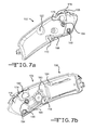
- FIG. 7 a is a perspective view of the inside of the left side (or main) body portion
- FIG. 7 b is a perspective view of the inside of the right front body portion and the right back body portion;
- FIG. 8 a is a perspective view of the inside of the right front body portion and the right back body portion, with the pushrod and return spring also shown;
- FIG. 8 b is a perspective view of the inside of the right front body portion and the right back body portion, with the pushrod, return spring, and slider also shown;
- FIG. 9 a is a back view of slider and pushrod shown together
- FIG. 9 b is a back view of the slider
- FIG. 10 a is right perspective view of the slider and pushrod shown together;
- FIG. 10 b is right perspective view of the slider
- FIG. 11 a is a perspective view of the right back body portion separated from the left side (or main) body portion showing the spare blade dispenser secured to the right back body portion;
- FIG. 11 b is a perspective view of the right back body portion of FIG. 11 a shown with the spare blade dispenser separated there from;
- FIGS. 12 a , 12 b , 13 a and 13 b illustrate operation of the blade depth adjustment assembly
- FIGS. 14 a - 14 c illustrate how movement of the blade release member causes the blade hood to retract from its default extended position
- FIGS. 15 a and 15 b are right and left side views, respectively, of the blade carrier, blade, blade hood, pushrod, and blade release member;
- FIG. 15 c is a left perspective view of the blade carrier, blade, pushrod, and blade release member
- FIG. 15 d is a left perspective view of the blade carrier, blade, and pushrod;
- FIG. 15 e is a left perspective view of the blade carrier and pushrod
- FIG. 16 a illustrates how the right back portion of the utility knife can be pivoted to an opened position to reveal the spare blade dispenser secured therein;
- FIG. 16 b illustrates how the shuttle of the spare blade dispenser engages and extends a topmost spare blade from the blade receptacle
- FIG. 16 c is a perspective view of the shuttle shown with a blade supported thereon.
- a utility knife 100 includes a left (or main) body portion 102 , a right front body portion 104 , and a right back body portion 106 , formed as shown. Assembled, the left body portion 102 , the right front body portion 104 , and the right back body portion 106 provide a handle for the utility knife 100 .
- the left body portion 102 , the right front body portion 104 , and the right back body portion 106 are made of a rigid, durable material such as zinc. It should be appreciated, however, that other materials can also be used.
- the left body portion 102 includes openings 108 and 110 ( FIG. 7 a ) through which screws 112 and 114 ( FIG. 1 a ) are inserted and secured within threaded openings 116 and 118 ( FIG. 7 b ), respectively.
- the right back body portion 106 and the left body portion 102 are pivotally secured together as shown with a pin 120 ( FIG. 1 b ).
- the left body portion 102 includes an opening 122 ( FIG. 7 a ) and the right back body portion 106 includes a threaded opening 124 ( FIG. 7 b ) into which a lock device 126 ( FIG.
- the lock device 126 is configured to selectively secure the right back body portion 106 in a closed position or release the right back body portion 106 such that it can be repositioned to an opened position.
- the lock wheel is accessible external to the main portion and extends there through to engage with or disengage from the back body portion depending upon which direction the lock wheel is turned in relation to the main portion.
- the utility knife 100 further includes a blade carrier 130 , a blade hood 132 , a pushrod 134 , a blade release member 136 , and a slider 138 , configured as shown.
- the blade carrier 130 (e.g., made from zinc) is mechanically coupled to the handle and configured to support a blade 140 ( FIG. 15 d ).
- the blade hood 132 (e.g., made from sheet metal) is mechanically coupled to the handle facilitating manipulability of the blade hood 132 to an extended position over the blade 140 ( FIG. 14 a ).
- the blade hood 132 is pivotally coupled to the handle.
- the blade hood 132 includes cylindrical channels 142 on opposite sides of the blade hood 132 .
- the cylindrical channels 142 are sized to receive bearings 144 of the pushrod 134 .
- cylindrical channels 146 of the blade hood 132 are sized to receive hood pivots 148 from opposite sides of the blade hood 132 , thereby pivotally securing the blade hood 132 to the handle.
- the pushrod 134 (e.g., made from POM or metal) is mechanically coupled to the blade hood 132 and includes a protrusion 150 ( FIG. 4 a ) that extends toward the blade carrier 130 .
- the pushrod 134 includes a lift ramp 152 and a spring anchor 154 ( FIG. 15 c ) formed as shown.
- the pushrod 134 is entirely rigid.
- an end portion 156 of the pushrod 134 is positioned adjacent to a stop 160 ( FIG. 7 b ) in the handle when the blade hood 132 is in its extended position.
- a spring 158 ( FIG.
- the blade release member 136 (e.g., made from POM) includes a button 164 that extends through a slot 166 in the housing.
- the blade release member 136 is mechanically engaged with the blade carrier 130 to slide there along when the button 164 is moved along the slot 166 .
- the blade release member 136 includes an upper portion 168 ( FIG. 15 a ) that makes contact with the protrusion 150 (of the pushrod 134 ) when the blade release member 136 is moved along the slot 166 such that the pushrod 134 is repositioned within the handle and the blade hood 132 is retracted from the extended position to allow the blade 140 to be removed from the blade carrier 130 .
- the slider 138 (e.g., made from POM), in this example embodiment, includes buttons 170 , 172 and 174 which extend respectively through openings 176 , 178 and 180 in the handle.
- the slider includes one or more buttons that extend through the handle, at least one of the buttons extending through a top side of the handle opposite a cutting edge of the blade.
- the slider 138 includes cylindrical channels 182 which are formed and sized as shown to receive bearings 184 ( FIGS. 7 a and 7 b ) for pivotally coupling the slider 138 to the handle.
- the slider 138 includes a lifter member (or lifter) 186 ( FIG. 8 b ) formed as shown.
- the slider 138 includes a return spring 188 formed as shown. As discussed below, the return spring 188 imparts a force tending to urge the slider 138 away from a position that releases the blade hood 132 .
- the blade hood 132 needs to be released from its extended position both when the utility knife is to be used to cut a work piece, as well as when a forward blade change operation is to be performed.
- a function of the slider 138 is to release the blade hood 132 from being locked into its extended position. This is accomplished by repositioning the slider 138 along the handle (i.e., by pushing any one of the buttons 170 , 172 and 174 forward). More specifically, the slider 138 is configured to manipulate the pushrod 134 in relation to the stop 160 . When the slider 138 is pushed forward, the lifter member 186 bears against the lift ramp 152 of the pushrod 134 , raising the end portion 156 allowing the pushrod 134 to traverse the stop 160 .
- FIGS. 14 a - 14 c illustrate how movement of the blade release member 136 causes the blade hood 132 to retract from its default extended position.
- it is first necessary to reposition the slider 138 forward (to facilitate movement of the pushrod 134 past the stop 160 ) prior to repositioning the blade release member 136 along the slot 166 to release the blade 140 .
- the upper portion 168 comes into contact with the protrusion 150 . This causes the pushrod 134 to move backward along the handle along with the blade release member 136 .
- the utility knife 100 includes a blade depth adjustment assembly 190 which is mechanically coupled to the handle and configured to permit a user of the utility knife 100 to reposition components of the blade depth adjustment assembly 190 to select one of multiple blade depth positions which causes the blade carrier 130 to be repositioned along the handle depending upon which of the blade depth positions is selected.
- the blade depth adjustment assembly 190 includes a wheel 192 , a depth selector member 194 , a spring 196 , and a gear 198 , formed and configured as shown such that the blade carrier 130 is repositioned along the handle in response to the wheel 192 being repositioned in relation to the handle.
- the wheel 192 extends from an opening 200 ( FIG. 6 b ) in the handle. More specifically, in this example embodiment, the depth selector member 194 interfits with the wheel 192 and includes a shaft 202 that passes through an opening 204 in the wheel 192 and also through the opening 200 . In this example embodiment, the wheel 192 includes a channel 206 and the depth selector member 194 is configured to be seated within the channel 206 when the depth selector member 194 has locked the blade carrier 130 into a selected blade depth position.
- the depth selector member 194 is formed and configured to lock the blade carrier 130 into a selected blade depth position. More specifically, the right front body portion 104 includes recessed portions 208 ( FIG. 6 b ) as shown, and the depth selector member 194 includes a peg 210 (in this example embodiment, two pegs 210 ) sized to interlock with one of the recessed portions 208 depending upon which of the blade depth positions is selected.
- the spring 196 is configured to bias the depth selector member 194 toward a position where the depth selector member 194 locks the blade carrier, i.e., the spring imparts a force that seeks to pull the peg 210 into whichever recessed portion 208 it is positioned over.
- the spring 196 which is fitted over the shaft 202 , is positioned between the gear 198 and the right front body portion 104 .
- the gear 198 is secured to the shaft 202 and mechanically engages with a complementary surface 212 (e.g., a surface with teeth complementary to those of the gear 198 ) of the blade carrier 130 .
- a complementary surface 212 e.g., a surface with teeth complementary to those of the gear 198
- the depth selector member 194 is pulled (against the force of the spring 196 ) to withdraw the peg 210 from whatever recessed portion 208 it was previously seated in. This frees the wheel 192 to be rotated.
- the gear 198 is fixed in relation to the wheel and, therefore, rotation of the gear 198 causes the blade carrier 130 to move laterally along the length of the handle depending upon which direction the wheel 192 is being turned.
- the utility knife 100 also includes a spare blade dispenser 220 secured to the right back body portion (back portion) 106 to be accessible by a user of the utility knife 100 when the back portion is in the opened position.
- the spare blade dispenser 220 includes a blade receptacle 222 sized to hold spare blades 224 and a shuttle 226 mechanically coupled to the blade receptacle 222 such that the shuttle 226 , when repositioned laterally with respect to the blade receptacle 222 , engages and extends a topmost spare blade 224 from the blade receptacle 222 .
- the spare blade dispenser 220 includes a spring 228 (e.g., a leaf spring) configured to bias the spare blades 224 toward the shuttle 226 .
- the spare blade dispenser 220 is detachably secured to the back portion facilitating replacement of the entire spare blade dispenser 220 as a module.
- the spare blade dispenser 220 is snap fitted to the back portion.
Landscapes
- Life Sciences & Earth Sciences (AREA)
- Forests & Forestry (AREA)
- Engineering & Computer Science (AREA)
- Mechanical Engineering (AREA)
- Knives (AREA)
Abstract
Description
Claims (7)
Priority Applications (2)
| Application Number | Priority Date | Filing Date | Title |
|---|---|---|---|
| US13/411,545 US8904649B2 (en) | 2009-02-26 | 2012-03-03 | Utility knife |
| US14/564,661 US9676107B2 (en) | 2009-02-26 | 2014-12-09 | Utility knife |
Applications Claiming Priority (2)
| Application Number | Priority Date | Filing Date | Title |
|---|---|---|---|
| US12/393,719 US8127452B2 (en) | 2009-02-26 | 2009-02-26 | Utility knife |
| US13/411,545 US8904649B2 (en) | 2009-02-26 | 2012-03-03 | Utility knife |
Related Parent Applications (1)
| Application Number | Title | Priority Date | Filing Date |
|---|---|---|---|
| US12/393,719 Division US8127452B2 (en) | 2009-02-26 | 2009-02-26 | Utility knife |
Related Child Applications (1)
| Application Number | Title | Priority Date | Filing Date |
|---|---|---|---|
| US14/564,661 Division US9676107B2 (en) | 2009-02-26 | 2014-12-09 | Utility knife |
Publications (2)
| Publication Number | Publication Date |
|---|---|
| US20120279071A1 US20120279071A1 (en) | 2012-11-08 |
| US8904649B2 true US8904649B2 (en) | 2014-12-09 |
Family
ID=42629625
Family Applications (3)
| Application Number | Title | Priority Date | Filing Date |
|---|---|---|---|
| US12/393,719 Active 2030-04-06 US8127452B2 (en) | 2009-02-26 | 2009-02-26 | Utility knife |
| US13/411,545 Active US8904649B2 (en) | 2009-02-26 | 2012-03-03 | Utility knife |
| US14/564,661 Active US9676107B2 (en) | 2009-02-26 | 2014-12-09 | Utility knife |
Family Applications Before (1)
| Application Number | Title | Priority Date | Filing Date |
|---|---|---|---|
| US12/393,719 Active 2030-04-06 US8127452B2 (en) | 2009-02-26 | 2009-02-26 | Utility knife |
Family Applications After (1)
| Application Number | Title | Priority Date | Filing Date |
|---|---|---|---|
| US14/564,661 Active US9676107B2 (en) | 2009-02-26 | 2014-12-09 | Utility knife |
Country Status (1)
| Country | Link |
|---|---|
| US (3) | US8127452B2 (en) |
Cited By (8)
| Publication number | Priority date | Publication date | Assignee | Title |
|---|---|---|---|---|
| US20150283712A1 (en) * | 2009-02-26 | 2015-10-08 | Pacific Handy Cutter, Inc. | Utility Knife |
| US20160214264A1 (en) * | 2015-01-28 | 2016-07-28 | Pacific Handy Cutter, Inc. | Safety Cutter |
| US20170021511A1 (en) * | 2015-07-20 | 2017-01-26 | Goodly-Ch Enterprise Co., Ltd. | Utility Knife |
| US9840013B2 (en) | 2008-04-29 | 2017-12-12 | Pacific Handy Cutter, Inc. | Safety cutter with blade change/storage mechanism |
| US20180133908A1 (en) * | 2016-11-17 | 2018-05-17 | Goodrich Corporation | Safety knife with retractable sheath |
| US11498199B2 (en) | 2018-07-09 | 2022-11-15 | Milwaukee Electric Tool Corporation | Utility knife with tape hook recess |
| US20230264372A1 (en) * | 2022-02-18 | 2023-08-24 | Zeluga, Inc. | Hinged utility knife |
| US12365104B2 (en) | 2020-03-06 | 2025-07-22 | Milwaukee Electric Tool Corporation | Knife with blade storage |
Families Citing this family (26)
| Publication number | Priority date | Publication date | Assignee | Title |
|---|---|---|---|---|
| US9676106B2 (en) | 2008-04-29 | 2017-06-13 | Pacific Handy Cutter, Inc. | Safety cutter with guard-actuated blade deployment |
| US10093026B2 (en) | 2008-04-29 | 2018-10-09 | Pacific Handy Cutter, Inc. | Safety cutter with blade depth selector/interlock mechanism |
| US20100305593A1 (en) * | 2009-05-29 | 2010-12-02 | Inzero John R | Safety scalpel |
| US8539677B2 (en) * | 2010-08-17 | 2013-09-24 | Irwin Industrial Tool Company | Utility knife |
| US8776380B1 (en) * | 2011-04-25 | 2014-07-15 | Elwood Dean Quimby | Utility knife with retractable blade |
| USD699090S1 (en) * | 2011-05-09 | 2014-02-11 | Jpj Investment Holding Corp. | Knife |
| US8720068B2 (en) * | 2012-01-19 | 2014-05-13 | Ritesafety Products International, Llc | Hand cutter with blade guard |
| USD692657S1 (en) | 2012-10-01 | 2013-11-05 | Milwaukee Electric Tool Corporation | Utility knife blade case |
| US9003668B2 (en) * | 2012-10-18 | 2015-04-14 | Ritesafety Products International, Llc | Hand cutter with blade guard |
| NO337131B1 (en) * | 2012-12-28 | 2016-01-25 | 1Diamond Llc | A sawing system, a support structure for a saw and a sawmill swap unit |
| USD699540S1 (en) | 2013-01-18 | 2014-02-18 | Milwaukee Electric Tool Corporation | Utility knife |
| USD699092S1 (en) | 2013-01-18 | 2014-02-11 | Milwaukee Electric Tool Corporation | Utility knife |
| USD699541S1 (en) | 2013-01-18 | 2014-02-18 | Milwaukee Electric Tool Corporation | Utility knife |
| DE102013014684A1 (en) * | 2013-09-05 | 2015-03-05 | Martor Kg | knife |
| US9027254B1 (en) * | 2013-11-08 | 2015-05-12 | Bosela Design LLC | Scalpel handle having a blade shield |
| US9757146B2 (en) | 2013-11-08 | 2017-09-12 | Bosela Design LLC | Scalpel handle having a blade shield utilizing over center spring |
| US10231752B2 (en) | 2013-11-08 | 2019-03-19 | Bosela Design LLC | Scalpel handle having a blade shield utilizing over center spring |
| CN104545560A (en) * | 2014-12-24 | 2015-04-29 | 苏州用朴合金工具有限公司 | Fine adjustment type clamping cutter |
| USD749928S1 (en) * | 2014-12-29 | 2016-02-23 | Js Products, Inc. | Utility knife handle |
| USD749929S1 (en) * | 2014-12-29 | 2016-02-23 | Js Products, Inc. | Utility knife handle |
| CN106553211B (en) * | 2016-11-30 | 2019-07-02 | 国家电网公司 | A cable opening device |
| US10179415B2 (en) * | 2017-03-30 | 2019-01-15 | Ritesafety Products International, Llc | Hand cutter with a retractable blade |
| NO345448B1 (en) | 2018-01-30 | 2021-02-01 | 1Diamond As | Inclined cut GBS leg |
| US11161265B2 (en) * | 2020-01-30 | 2021-11-02 | Slice, Inc. | Compact safety cutter |
| CN112192618B (en) * | 2020-09-04 | 2025-02-11 | 广州宝瑰贸易有限公司 | A trigger knife |
| CN112171722B (en) * | 2020-09-04 | 2025-03-14 | 广州宝瑰贸易有限公司 | Push-type safety knife |
Citations (29)
| Publication number | Priority date | Publication date | Assignee | Title |
|---|---|---|---|---|
| US3577637A (en) * | 1968-09-24 | 1971-05-04 | Philip Morris Inc | Retractable blade knife |
| US3593417A (en) * | 1969-08-13 | 1971-07-20 | Stanley Works | Hand tool having a holder for spare blades and the like |
| US3857176A (en) * | 1972-12-11 | 1974-12-31 | Stanley Mabo | Knife with a retractable blade |
| US5613300A (en) * | 1993-01-12 | 1997-03-25 | Pacific Handy Cutter | Ergonomic utility knife/box cutter and method of making |
| US5940970A (en) * | 1997-08-07 | 1999-08-24 | Le-Jo Enterprises, Inc. | Utility knife |
| US6192589B1 (en) * | 1999-06-25 | 2001-02-27 | The Stanley Works | Utility knife |
| US6330749B1 (en) * | 1999-08-14 | 2001-12-18 | Olympia Group, Inc. | Adjustable safety utility knife with easily removable blade holder |
| US6349473B1 (en) * | 2000-08-11 | 2002-02-26 | Alterra Holdings Corporation | Utility knife |
| US6374496B1 (en) * | 2001-01-22 | 2002-04-23 | Cheng-Hui Hsu | Structure art design knife |
| GB2377403A (en) * | 2001-07-09 | 2003-01-15 | Taiwan San Tyau Co Ltd | Utility cutter |
| US20030037444A1 (en) * | 2001-08-21 | 2003-02-27 | Chunn Steve Howard | Ergonomically shaped, fixed blade, front loading utility knife with extra blades storage compartment having single blade retrieval system |
| US6574872B2 (en) * | 2001-05-04 | 2003-06-10 | The Stanley Works | Utility knife |
| US6807738B1 (en) * | 2002-10-04 | 2004-10-26 | Shih-Chin Shih | Blade gripping mechanism in a heavy duty artistic knife |
| US6829827B2 (en) * | 2001-08-06 | 2004-12-14 | Han Chung Tseng | Artistic knife with spare blades |
| US6845561B2 (en) * | 2002-09-13 | 2005-01-25 | T&J Llc | Replaceable-blade knife |
| US20060010694A1 (en) * | 2004-07-16 | 2006-01-19 | Chen Yi Y | Knife assembly having quick release blade magazine |
| US20060080842A1 (en) * | 2004-10-15 | 2006-04-20 | Pacific Handy Cutter, Inc. | Safety cutter with triple locking slider |
| US20060107532A1 (en) * | 2004-11-22 | 2006-05-25 | Fu-Cheng Sun | Art design knife |
| US7100285B1 (en) * | 2003-11-13 | 2006-09-05 | Yin-Hai Huang | Self-opening handle for a heavy duty artistic knife |
| US20070294896A1 (en) * | 2003-11-10 | 2007-12-27 | Brown Donald A | Utility knife |
| US7389587B2 (en) * | 2005-09-08 | 2008-06-24 | Helen Of Troy Limited | Utility knife |
| US7621051B2 (en) * | 2004-03-19 | 2009-11-24 | Great Neck Saw Manufacturers, Inc. | Utility knife |
| US20100037467A1 (en) * | 2008-08-15 | 2010-02-18 | The Stanley Works | Utility knife with blade wiper |
| US7987602B2 (en) * | 2007-10-14 | 2011-08-02 | Pacific Handy Cutter, Inc. | Safety cutter apparatus |
| US8127452B2 (en) * | 2009-02-26 | 2012-03-06 | Pacific Handy Cutter, Inc. | Utility knife |
| US20120102754A1 (en) * | 2008-04-29 | 2012-05-03 | Garavaglia Joseph P | Safety Cutter with Guard-actuated Blade Deployment |
| US20120216412A1 (en) * | 2008-04-29 | 2012-08-30 | Yen-Chao Chung | Spring Back Safety and Film Cutter |
| US20130061479A1 (en) * | 2011-09-08 | 2013-03-14 | Joseph L. Lutgen | Safety Cutter with Improved Blade Storage Mechanism |
| US8539677B2 (en) * | 2010-08-17 | 2013-09-24 | Irwin Industrial Tool Company | Utility knife |
Family Cites Families (15)
| Publication number | Priority date | Publication date | Assignee | Title |
|---|---|---|---|---|
| US3781988A (en) * | 1972-08-29 | 1974-01-01 | R Jones | Safety paper carton opening blade holder |
| US3943627A (en) * | 1973-11-28 | 1976-03-16 | Stanley Jr Conrad | Front loading utility knife |
| US5241750A (en) * | 1992-04-30 | 1993-09-07 | Chomiak Bryant D | Utility razor safety knife |
| US5890290A (en) * | 1997-08-05 | 1999-04-06 | Davis; Raymond E. | Adjustable depth safety cutter |
| US5878501A (en) * | 1997-08-08 | 1999-03-09 | The Stanley Works | Utility knife with retractable blade guard |
| US6178640B1 (en) * | 1999-08-09 | 2001-01-30 | Spellbound Development Group, Inc. | Slitter device |
| US6560873B1 (en) * | 1999-11-12 | 2003-05-13 | Mel Wayne Ortner | Automatic safety knife |
| US6578266B2 (en) * | 2000-12-07 | 2003-06-17 | Bryant D. Chomiak | Safety utility razor knife |
| US7356928B2 (en) * | 2004-09-08 | 2008-04-15 | Earl J. & Kimberly Votolato Trustees Of The Votolato Living Trust | Utility knife with safety guard having reduced play |
| US8220160B2 (en) * | 2005-09-16 | 2012-07-17 | Adco Industries-Technologies, L.P. | Box cutter with grip-actuated blade extension |
| US7774942B2 (en) * | 2006-10-09 | 2010-08-17 | Pacific Handy Cutter, Inc. | Utility knife |
| ES2368529T3 (en) * | 2007-04-16 | 2011-11-18 | Adco Industries, A Subsidiary Of Dallco Marketing, Inc. | CUTTING OF RIGID AND SEMIRIGID MATERIAL. |
| US8720068B2 (en) * | 2012-01-19 | 2014-05-13 | Ritesafety Products International, Llc | Hand cutter with blade guard |
| US8769826B2 (en) * | 2012-07-11 | 2014-07-08 | Yuewei Wu | Cutting device |
| US9003668B2 (en) * | 2012-10-18 | 2015-04-14 | Ritesafety Products International, Llc | Hand cutter with blade guard |
-
2009
- 2009-02-26 US US12/393,719 patent/US8127452B2/en active Active
-
2012
- 2012-03-03 US US13/411,545 patent/US8904649B2/en active Active
-
2014
- 2014-12-09 US US14/564,661 patent/US9676107B2/en active Active
Patent Citations (29)
| Publication number | Priority date | Publication date | Assignee | Title |
|---|---|---|---|---|
| US3577637A (en) * | 1968-09-24 | 1971-05-04 | Philip Morris Inc | Retractable blade knife |
| US3593417A (en) * | 1969-08-13 | 1971-07-20 | Stanley Works | Hand tool having a holder for spare blades and the like |
| US3857176A (en) * | 1972-12-11 | 1974-12-31 | Stanley Mabo | Knife with a retractable blade |
| US5613300A (en) * | 1993-01-12 | 1997-03-25 | Pacific Handy Cutter | Ergonomic utility knife/box cutter and method of making |
| US5940970A (en) * | 1997-08-07 | 1999-08-24 | Le-Jo Enterprises, Inc. | Utility knife |
| US6192589B1 (en) * | 1999-06-25 | 2001-02-27 | The Stanley Works | Utility knife |
| US6330749B1 (en) * | 1999-08-14 | 2001-12-18 | Olympia Group, Inc. | Adjustable safety utility knife with easily removable blade holder |
| US6349473B1 (en) * | 2000-08-11 | 2002-02-26 | Alterra Holdings Corporation | Utility knife |
| US6374496B1 (en) * | 2001-01-22 | 2002-04-23 | Cheng-Hui Hsu | Structure art design knife |
| US6574872B2 (en) * | 2001-05-04 | 2003-06-10 | The Stanley Works | Utility knife |
| GB2377403A (en) * | 2001-07-09 | 2003-01-15 | Taiwan San Tyau Co Ltd | Utility cutter |
| US6829827B2 (en) * | 2001-08-06 | 2004-12-14 | Han Chung Tseng | Artistic knife with spare blades |
| US20030037444A1 (en) * | 2001-08-21 | 2003-02-27 | Chunn Steve Howard | Ergonomically shaped, fixed blade, front loading utility knife with extra blades storage compartment having single blade retrieval system |
| US6845561B2 (en) * | 2002-09-13 | 2005-01-25 | T&J Llc | Replaceable-blade knife |
| US6807738B1 (en) * | 2002-10-04 | 2004-10-26 | Shih-Chin Shih | Blade gripping mechanism in a heavy duty artistic knife |
| US20070294896A1 (en) * | 2003-11-10 | 2007-12-27 | Brown Donald A | Utility knife |
| US7100285B1 (en) * | 2003-11-13 | 2006-09-05 | Yin-Hai Huang | Self-opening handle for a heavy duty artistic knife |
| US7621051B2 (en) * | 2004-03-19 | 2009-11-24 | Great Neck Saw Manufacturers, Inc. | Utility knife |
| US20060010694A1 (en) * | 2004-07-16 | 2006-01-19 | Chen Yi Y | Knife assembly having quick release blade magazine |
| US20060080842A1 (en) * | 2004-10-15 | 2006-04-20 | Pacific Handy Cutter, Inc. | Safety cutter with triple locking slider |
| US20060107532A1 (en) * | 2004-11-22 | 2006-05-25 | Fu-Cheng Sun | Art design knife |
| US7389587B2 (en) * | 2005-09-08 | 2008-06-24 | Helen Of Troy Limited | Utility knife |
| US7987602B2 (en) * | 2007-10-14 | 2011-08-02 | Pacific Handy Cutter, Inc. | Safety cutter apparatus |
| US20120102754A1 (en) * | 2008-04-29 | 2012-05-03 | Garavaglia Joseph P | Safety Cutter with Guard-actuated Blade Deployment |
| US20120216412A1 (en) * | 2008-04-29 | 2012-08-30 | Yen-Chao Chung | Spring Back Safety and Film Cutter |
| US20100037467A1 (en) * | 2008-08-15 | 2010-02-18 | The Stanley Works | Utility knife with blade wiper |
| US8127452B2 (en) * | 2009-02-26 | 2012-03-06 | Pacific Handy Cutter, Inc. | Utility knife |
| US8539677B2 (en) * | 2010-08-17 | 2013-09-24 | Irwin Industrial Tool Company | Utility knife |
| US20130061479A1 (en) * | 2011-09-08 | 2013-03-14 | Joseph L. Lutgen | Safety Cutter with Improved Blade Storage Mechanism |
Cited By (12)
| Publication number | Priority date | Publication date | Assignee | Title |
|---|---|---|---|---|
| US9840013B2 (en) | 2008-04-29 | 2017-12-12 | Pacific Handy Cutter, Inc. | Safety cutter with blade change/storage mechanism |
| US20150283712A1 (en) * | 2009-02-26 | 2015-10-08 | Pacific Handy Cutter, Inc. | Utility Knife |
| US9676107B2 (en) * | 2009-02-26 | 2017-06-13 | Pacific Handy Cutter, Inc. | Utility knife |
| US20160214264A1 (en) * | 2015-01-28 | 2016-07-28 | Pacific Handy Cutter, Inc. | Safety Cutter |
| US10093027B2 (en) * | 2015-01-28 | 2018-10-09 | Pacific Handy Cutter, Inc. | Safety cutter |
| US20170021511A1 (en) * | 2015-07-20 | 2017-01-26 | Goodly-Ch Enterprise Co., Ltd. | Utility Knife |
| US10213927B2 (en) * | 2015-07-20 | 2019-02-26 | Goodly-Ch Enterprise Co., Ltd. | Utility knife |
| US20180133908A1 (en) * | 2016-11-17 | 2018-05-17 | Goodrich Corporation | Safety knife with retractable sheath |
| US10207414B2 (en) * | 2016-11-17 | 2019-02-19 | Goodrich Corporation | Safety knife with retractable sheath |
| US11498199B2 (en) | 2018-07-09 | 2022-11-15 | Milwaukee Electric Tool Corporation | Utility knife with tape hook recess |
| US12365104B2 (en) | 2020-03-06 | 2025-07-22 | Milwaukee Electric Tool Corporation | Knife with blade storage |
| US20230264372A1 (en) * | 2022-02-18 | 2023-08-24 | Zeluga, Inc. | Hinged utility knife |
Also Published As
| Publication number | Publication date |
|---|---|
| US9676107B2 (en) | 2017-06-13 |
| US20150283712A1 (en) | 2015-10-08 |
| US8127452B2 (en) | 2012-03-06 |
| US20100212164A1 (en) | 2010-08-26 |
| US20120279071A1 (en) | 2012-11-08 |
Similar Documents
| Publication | Publication Date | Title |
|---|---|---|
| US8904649B2 (en) | Utility knife | |
| US9956695B2 (en) | Spring back safety and film cutter | |
| US8955226B2 (en) | Utility knife | |
| US20130276312A1 (en) | Utility knife including a locking mechanism and/or ratcheting mechanism | |
| US9925674B2 (en) | Pocket cutter | |
| US8793882B2 (en) | Safety cutter apparatus | |
| US8769826B2 (en) | Cutting device | |
| US9676106B2 (en) | Safety cutter with guard-actuated blade deployment | |
| US12515359B2 (en) | Safety cutter with blade change/storage mechanism | |
| US20090277016A1 (en) | Utility knife with an auto-retractable blade | |
| TWI850250B (en) | Knife with handle and blade | |
| US10093026B2 (en) | Safety cutter with blade depth selector/interlock mechanism | |
| US20230249369A1 (en) | Pocket cutter | |
| US8813367B1 (en) | Bolster lock tool | |
| AU2013202032A1 (en) | A cutting device | |
| WO2008016720A2 (en) | Utility knife | |
| CA2631792A1 (en) | A utility knife with an auto-retractable blade |
Legal Events
| Date | Code | Title | Description |
|---|---|---|---|
| STCF | Information on status: patent grant |
Free format text: PATENTED CASE |
|
| AS | Assignment |
Owner name: PACIFIC HANDY CUTTER, INC., CALIFORNIA Free format text: RELEASE BY SECURED PARTY;ASSIGNOR:ABACUS FINANCE GROUP, LLC, AS ADMINISTRATIVE AGENT;REEL/FRAME:044769/0453 Effective date: 20180130 |
|
| AS | Assignment |
Owner name: MADISON CAPITAL FUNDING LLC, ILLINOIS Free format text: SECURITY INTEREST;ASSIGNOR:PACIFIC HANDY CUTTER, INC.;REEL/FRAME:045201/0097 Effective date: 20180130 |
|
| AS | Assignment |
Owner name: LEVINE LEICHTMAN CAPITAL PARTNERS SBIC FUND, L.P., Free format text: SECURITY INTEREST;ASSIGNOR:PACIFIC HANDY CUTTER, INC.;REEL/FRAME:045215/0766 Effective date: 20180130 |
|
| FEPP | Fee payment procedure |
Free format text: MAINTENANCE FEE REMINDER MAILED (ORIGINAL EVENT CODE: REM.) |
|
| FEPP | Fee payment procedure |
Free format text: SURCHARGE FOR LATE PAYMENT, SMALL ENTITY (ORIGINAL EVENT CODE: M2554); ENTITY STATUS OF PATENT OWNER: SMALL ENTITY |
|
| MAFP | Maintenance fee payment |
Free format text: PAYMENT OF MAINTENANCE FEE, 4TH YR, SMALL ENTITY (ORIGINAL EVENT CODE: M2551); ENTITY STATUS OF PATENT OWNER: SMALL ENTITY Year of fee payment: 4 |
|
| AS | Assignment |
Owner name: PACIFIC HANDY CUTTER, INC., CALIFORNIA Free format text: RELEASE BY SECURED PARTY;ASSIGNOR:LEVINE LEICHTMAN SMALL BUSINESS FUND, L.P.;REEL/FRAME:054791/0664 Effective date: 20201216 Owner name: PACIFIC HANDY CUTTER, INC., CALIFORNIA Free format text: RELEASE BY SECURED PARTY;ASSIGNOR:MADISON CAPITAL FUNDING LLC;REEL/FRAME:054793/0001 Effective date: 20201216 |
|
| AS | Assignment |
Owner name: BARINGS FINANCE LLC, NORTH CAROLINA Free format text: SECURITY INTEREST;ASSIGNOR:PACIFIC HANDY CUTTER, INC.;REEL/FRAME:054798/0528 Effective date: 20201216 |
|
| FEPP | Fee payment procedure |
Free format text: MAINTENANCE FEE REMINDER MAILED (ORIGINAL EVENT CODE: REM.); ENTITY STATUS OF PATENT OWNER: SMALL ENTITY |
|
| FEPP | Fee payment procedure |
Free format text: 7.5 YR SURCHARGE - LATE PMT W/IN 6 MO, SMALL ENTITY (ORIGINAL EVENT CODE: M2555); ENTITY STATUS OF PATENT OWNER: SMALL ENTITY |
|
| MAFP | Maintenance fee payment |
Free format text: PAYMENT OF MAINTENANCE FEE, 8TH YR, SMALL ENTITY (ORIGINAL EVENT CODE: M2552); ENTITY STATUS OF PATENT OWNER: SMALL ENTITY Year of fee payment: 8 |