US8900452B2 - Self-centering filters, coalescers and separators - Google Patents

Self-centering filters, coalescers and separators Download PDF

Info

Publication number
US8900452B2
US8900452B2 US12/462,842 US46284209A US8900452B2 US 8900452 B2 US8900452 B2 US 8900452B2 US 46284209 A US46284209 A US 46284209A US 8900452 B2 US8900452 B2 US 8900452B2
Authority
US
United States
Prior art keywords
cylindrical element
open end
open side
communication
rod
Prior art date
Legal status (The legal status is an assumption and is not a legal conclusion. Google has not performed a legal analysis and makes no representation as to the accuracy of the status listed.)
Active, expires
Application number
US12/462,842
Other versions
US20100116350A1 (en
Inventor
Richard E. Honchen
John Zuniga
Current Assignee (The listed assignees may be inaccurate. Google has not performed a legal analysis and makes no representation or warranty as to the accuracy of the list.)
Individual
Original Assignee
Individual
Priority date (The priority date is an assumption and is not a legal conclusion. Google has not performed a legal analysis and makes no representation as to the accuracy of the date listed.)
Filing date
Publication date
Application filed by Individual filed Critical Individual
Priority to US12/462,842 priority Critical patent/US8900452B2/en
Publication of US20100116350A1 publication Critical patent/US20100116350A1/en
Application granted granted Critical
Publication of US8900452B2 publication Critical patent/US8900452B2/en
Active legal-status Critical Current
Adjusted expiration legal-status Critical

Links

Images

Classifications

    • BPERFORMING OPERATIONS; TRANSPORTING
    • B01PHYSICAL OR CHEMICAL PROCESSES OR APPARATUS IN GENERAL
    • B01DSEPARATION
    • B01D29/00Filters with filtering elements stationary during filtration, e.g. pressure or suction filters, not covered by groups B01D24/00 - B01D27/00; Filtering elements therefor
    • B01D29/01Filters with filtering elements stationary during filtration, e.g. pressure or suction filters, not covered by groups B01D24/00 - B01D27/00; Filtering elements therefor with flat filtering elements
    • B01D29/012Making filtering elements
    • B01D29/006
    • BPERFORMING OPERATIONS; TRANSPORTING
    • B01PHYSICAL OR CHEMICAL PROCESSES OR APPARATUS IN GENERAL
    • B01DSEPARATION
    • B01D29/00Filters with filtering elements stationary during filtration, e.g. pressure or suction filters, not covered by groups B01D24/00 - B01D27/00; Filtering elements therefor
    • B01D29/96Filters with filtering elements stationary during filtration, e.g. pressure or suction filters, not covered by groups B01D24/00 - B01D27/00; Filtering elements therefor in which the filtering elements are moved between filtering operations; Particular measures for removing or replacing the filtering elements; Transport systems for filters
    • BPERFORMING OPERATIONS; TRANSPORTING
    • B01PHYSICAL OR CHEMICAL PROCESSES OR APPARATUS IN GENERAL
    • B01DSEPARATION
    • B01D46/00Filters or filtering processes specially modified for separating dispersed particles from gases or vapours
    • B01D46/0002Casings; Housings; Frame constructions
    • B01D46/0005Mounting of filtering elements within casings, housings or frames
    • BPERFORMING OPERATIONS; TRANSPORTING
    • B01PHYSICAL OR CHEMICAL PROCESSES OR APPARATUS IN GENERAL
    • B01DSEPARATION
    • B01D46/00Filters or filtering processes specially modified for separating dispersed particles from gases or vapours
    • B01D46/24Particle separators, e.g. dust precipitators, using rigid hollow filter bodies
    • B01D46/2403Particle separators, e.g. dust precipitators, using rigid hollow filter bodies characterised by the physical shape or structure of the filtering element
    • B01D46/2411Filter cartridges
    • BPERFORMING OPERATIONS; TRANSPORTING
    • B01PHYSICAL OR CHEMICAL PROCESSES OR APPARATUS IN GENERAL
    • B01DSEPARATION
    • B01D2201/00Details relating to filtering apparatus
    • B01D2201/40Special measures for connecting different parts of the filter
    • B01D2201/4046Means for avoiding false mounting of different parts
    • BPERFORMING OPERATIONS; TRANSPORTING
    • B01PHYSICAL OR CHEMICAL PROCESSES OR APPARATUS IN GENERAL
    • B01DSEPARATION
    • B01D2265/00Casings, housings or mounting for filters specially adapted for separating dispersed particles from gases or vapours
    • B01D2265/02Non-permanent measures for connecting different parts of the filter
    • B01D2265/024Mounting aids
    • B01D2265/026Mounting aids with means for avoiding false mounting
    • YGENERAL TAGGING OF NEW TECHNOLOGICAL DEVELOPMENTS; GENERAL TAGGING OF CROSS-SECTIONAL TECHNOLOGIES SPANNING OVER SEVERAL SECTIONS OF THE IPC; TECHNICAL SUBJECTS COVERED BY FORMER USPC CROSS-REFERENCE ART COLLECTIONS [XRACs] AND DIGESTS
    • Y10TECHNICAL SUBJECTS COVERED BY FORMER USPC
    • Y10TTECHNICAL SUBJECTS COVERED BY FORMER US CLASSIFICATION
    • Y10T137/00Fluid handling
    • Y10T137/0318Processes
    • Y10T137/0402Cleaning, repairing, or assembling
    • YGENERAL TAGGING OF NEW TECHNOLOGICAL DEVELOPMENTS; GENERAL TAGGING OF CROSS-SECTIONAL TECHNOLOGIES SPANNING OVER SEVERAL SECTIONS OF THE IPC; TECHNICAL SUBJECTS COVERED BY FORMER USPC CROSS-REFERENCE ART COLLECTIONS [XRACs] AND DIGESTS
    • Y10TECHNICAL SUBJECTS COVERED BY FORMER USPC
    • Y10TTECHNICAL SUBJECTS COVERED BY FORMER US CLASSIFICATION
    • Y10T137/00Fluid handling
    • Y10T137/598With repair, tapping, assembly, or disassembly means

Definitions

  • This invention pertains generally to systems, apparatus and methods to aid in the installation of large cylindrical members/elements such as filters, separators, or coalescers that are installed in a horizontal orientation against a vertical seal plate.
  • the invention introduces an alignment member positioned at the insertion end of the cylindrical element so as to bisect or split the insertion end into separate portions and hold in position a center notch for use in interfacing with a horizontal fastening rod, and an associated methodology for installation that can greatly simplify the installation and centering of such cylindrical filters, separators, or coalescers.
  • cylindrical processing members serve in numerous capacities to filter, separate and/or coalesce substances in fluid or gaseous state.
  • processing members must often be installed into housings in a horizontal position with one of their cylindrical ends abutting and sealed to and over an aperture in a vertical seal plate.
  • the service access provided prevents the installer from being able to reach into the housing a sufficient distance to aid in installation/replacement.
  • the filters, separators, or coalescers that extend beyond the reach of the installer become very difficult to hold in place, and even more difficult to properly align to and on the housing sealing plate over the aperture (which is, typically, the furthest distance from the operator).
  • FIG. 1A provides a schematic illustration of a prior art cylindrical member 1 installed in a typical location abutting a vertical seal plate 2 in a tank 10 so as to cover an aperture 2 A passing through seal plate 2 .
  • FIG. 1B provides a more detailed view of cylindrical member 1 ; illustrating the multiple layers (e.g., designated layers 1 A, 1 B) comprising the body of cylindrical member 1 , as well as its o-ring 1 C, rim cap 1 D, and o-ring groove 1 E in rim cap 1 D.
  • layers 1 A, 1 B the multiple layers comprising the body of cylindrical member 1 , as well as its o-ring 1 C, rim cap 1 D, and o-ring groove 1 E in rim cap 1 D.
  • the access cover 3 provided in tank 10 is small and makes insertion of the cylindrical member 1 over a centering rod 4 difficult as well as making centering of open end 5 A in proper sealing position against plate 2 over aperture 2 A extremely awkward. These difficulties are exacerbated when said cylindrical member 1 , as is usual, has a closed end 5 B opposite open end 5 A. There is an axially aligned mounting hole 5 C for rod 4 in closed end 5 B, but the fact that this end is closed makes it virtually impossible to accurately align the other end (open end 5 A) of cylindrical member 1 for proper sealing in the closed space and circumstances outlined and described.
  • the centering element includes a notched member having an open side adapted for lateral capture of the rod along with a holding structure for holding the notched member in position proximate the central axis of cylindrical member 1 .
  • the holding structure includes a connector for connection of the self-centering element to the cylindrical element 1 , and a dividing member adapted to divide the open end 5 A of the cylindrical element 1 into portions in communication with the open side of the notch (into which the rod 4 is inserted) and portions not in communication with the open side of the notch.
  • the aforesaid connector can advantageously take the form of a member attached to the cylindrical element proximate said open end, a member attached to a rim of the cylindrical element proximate said open end, and/or a member forming a portion of the rim attached to the cylindrical element proximate said open end.
  • FIG. 1A provides a perspective view of a tank with a cylindrical member installed therein in accordance with the teachings of prior art, with elements within the tank indicated in a schematic manner.
  • FIG. 1B provides a perspective slightly exploded view of the open end of a cylindrical member in accordance with the teachings of prior art.
  • FIG. 2 provides a perspective view of a basic embodiment of the invention, illustrating a cylindrical member with bisecting centering brace or bracket in its open end in accordance with the teachings of the invention.
  • the cylindrical member is oriented with the centering bracket in its initial insertion position.
  • FIG. 3A provides a frontal view of the centering device of the basic embodiment, showing more exactly the features of the bisecting centering bracket of the invention.
  • FIG. 3B provides a perspective view of the centering device of the basic embodiment, showing more exactly the features of the bisecting centering bracket of the invention.
  • FIG. 3C provides a side view of the centering device of the basic embodiment, showing more exactly the features of the bisecting centering bracket of the invention.
  • FIG. 4 provides a somewhat schematic perspective view illustrating a cylindrical member with bisecting centering bracket in its open end being inserted over a centering rod in accordance with the teachings of the invention.
  • the cylindrical member is oriented with the centering bracket in its initial insertion position.
  • FIG. 5 provides a perspective view illustrating a cylindrical member with bisecting centering bracket in its open end in accordance with the teachings of the invention.
  • the cylindrical member is oriented with the centering bracket in its rotated position.
  • FIG. 6 provides a somewhat schematic perspective view illustrating a cylindrical member with bisecting centering bracket in its open end being inserted over a centering rod in accordance with the teachings of the invention.
  • the cylindrical member is oriented with the centering bracket in its rotated position.
  • FIG. 7A provides a frontal view illustrating the preferred embodiment of the invention.
  • FIG. 7B provides a side view illustrating the preferred embodiment of the invention.
  • FIG. 7C provides a detailed view of the area encompassed by arrows “G” of FIG. 7A .
  • FIG. 7D provides a detailed view of the area encompassed by arrows “F” of FIG. 7A
  • FIG. 8 provides a cross-sectional detail view taken through E-E of FIG. 7A .
  • FIGS. 9A , 9 B and 9 C provide schematic perspective views of the preferred embodiment of the invention.
  • the instant invention resolves and avoids the difficulties inherent in prior art by providing and supporting a notched member in the form of a centering notch 6 A, 60 A in the open insertion end 5 A of the cylindrical member 1 that is to be installed against vertical plate 2 so as to be in communication with aperture 2 A.
  • the holding structure of the centering device 6 takes the form of a bisecting brace or bracket with a center notch 6 A installed in or forming part of the open insertion end 5 A of the cylindrical member 1 .
  • the bisecting linear portion of centering device 6 forms a dividing member which divides the open end 5 A of cylindrical member 1 into portions in communication 5 A′ with open side 6 A′ of center notch 6 A (as well as portions not in communication with open side 6 A′).
  • the portion of the centering device 60 under (and not in communication with) the center notch 60 A is substantially closed with slots 60 C or other openings for fluid flow. The substantial closure of this half in the preferred embodiments prevents the operator from installing the coalescer on the wrong side of centering rod 4 . This addition does not impede the fluid flow, nor limit the access to install.
  • the invention with its center notch 6 A, 60 A with an open side 6 A′, 60 A′ is shaped such that when the cylindrical member 1 is partially installed over centering rod 4 with centering rod 4 in the portion in communication 5 A′ with open side 6 A′, 60 A′, the cylindrical member 1 can be rotated 180 degrees, causing the center notch 6 A, 60 A to engage and interface with the housing centering rod 4 , automatically centering the cylindrical member 1 by raising up the far end (i.e., open end 5 A) of the filter, separator, or coalescer (i.e., the cylindrical member 1 ) to align properly with the aperture 2 A in the housing sealing plate 2 .
  • the apparatus of the invention in its basic embodiment can be simply and easily constructed by adding a dividing member (bisecting centering device/bracket 6 ) to open end 5 A of cylindrical member 1 in the manner illustrated and previously described so as to form part of the holding structure for notch 6 A.
  • a dividing member bisecting centering device/bracket 6
  • appropriately shaped curved arms 6 B matching the inner curvature and dimensions of cylindrical member 1 can preferably be included at either end of centering bracket 6 to aid in its incorporation into cylindrical member 1 , to stabilize it in position, and for use in fastening it thereto (by welding, bolting or other means).
  • the initial insertion position is indicated in FIGS. 2 and 4 , where it can be seen that the entire upper half of the open end 5 A (i.e., the portions in communication 5 A′ with open side 6 A′) can be easily inserted over centering rod 4 .
  • the cylindrical member 1 is rotated around centering rod 4 , bringing bisecting centering bracket 6 to its rotated (centering) position in end 5 A of cylindrical member 1 . (See, FIGS. 5 and 6 ).
  • the act of rotation will elevate open end 5 A to a position more properly aligned over aperture 2 A in vertical plate 2 as centering bracket 6 is rotated to a position over centering rod 4 .
  • centering rod 4 does not slide automatically into notch 6 A, slight lateral adjustments can be used to nest centering rod 4 in the open side 6 A′ of central notch 6 A to more perfectly center and align open end 5 A for sealing contact over aperture 2 A in vertical plate 2 .
  • the centering device 60 is advantageously formed as part of rim 1 D and the portion of device 60 under its center notch 60 A is formed as a closed portion 60 B with a plurality of slots 60 C or other openings too small to allow insertion of rod 4 therethrough, but providing sufficient openings to allow free flow of gases and fluids. Closed portion 60 B prevents the operator from installing the cylindrical member with center notch 60 A on the wrong side of the centering rod 4 .
  • the dividing member formed by edge 60 B′ is tilted towards the open side 60 A′ of notch 60 A, so as to assist in sliding/ramping rod 4 and notch 60 A into engagement.
  • notch 60 A is formed with a semi-circular portion matching the peripheral dimensions of rod 4 so as to better engage rod 4 .

Landscapes

  • Chemical & Material Sciences (AREA)
  • Chemical Kinetics & Catalysis (AREA)
  • Physics & Mathematics (AREA)
  • Geometry (AREA)
  • Filtering Of Dispersed Particles In Gases (AREA)
  • Filtration Of Liquid (AREA)

Abstract

This self-centering device for cylindrical elements such as filters, coalescers and separators having a central axis and adapted for placement with an open end over and in communication with an aperture with a rod extending from its center incorporates or includes a notched member having an open side adapted for lateral capture of the rod along with a holding structure for holding the notched member in position proximate the central axis. The holding structure includes a connector for connection of the self-centering element to the cylindrical element, and a dividing member adapted to divide the open end of the cylindrical element into portions in communication with the open side and portions not in communication with the open side. The connector can advantageously take the form of a member attached to the cylindrical element proximate the open end, a member attached to a rim of the cylindrical element proximate said open end, and/or a member forming a portion of the rim attached to the cylindrical element proximate said open end.

Description

RELATED APPLICATIONS
This application claims an invention that was disclosed in U.S. Provisional Application No. 61/188,336, filed 8 Aug. 2008, entitled “Self-Centering Bracket for Filters, Coalescers and Separators”. The benefit under 35 USC §119(e) and/or other applicable law of the aforesaid United States provisional application is hereby claimed, and the aforementioned application is hereby incorporated herein by reference.
BACKGROUND AND SUMMARY
This invention pertains generally to systems, apparatus and methods to aid in the installation of large cylindrical members/elements such as filters, separators, or coalescers that are installed in a horizontal orientation against a vertical seal plate. The invention introduces an alignment member positioned at the insertion end of the cylindrical element so as to bisect or split the insertion end into separate portions and hold in position a center notch for use in interfacing with a horizontal fastening rod, and an associated methodology for installation that can greatly simplify the installation and centering of such cylindrical filters, separators, or coalescers.
Large cylindrical filters, separators, or coalescers (hereinafter also referred to as cylindrical processing members, cylindrical elements or cylindrical members) serve in numerous capacities to filter, separate and/or coalesce substances in fluid or gaseous state. Such processing members must often be installed into housings in a horizontal position with one of their cylindrical ends abutting and sealed to and over an aperture in a vertical seal plate. Quite often, due to cost, and space constraints, the service access provided prevents the installer from being able to reach into the housing a sufficient distance to aid in installation/replacement. The filters, separators, or coalescers that extend beyond the reach of the installer become very difficult to hold in place, and even more difficult to properly align to and on the housing sealing plate over the aperture (which is, typically, the furthest distance from the operator).
These problems can best be understood by reference to FIGS. 1A and 1B. FIG. 1A provides a schematic illustration of a prior art cylindrical member 1 installed in a typical location abutting a vertical seal plate 2 in a tank 10 so as to cover an aperture 2A passing through seal plate 2. FIG. 1B provides a more detailed view of cylindrical member 1; illustrating the multiple layers (e.g., designated layers 1A, 1B) comprising the body of cylindrical member 1, as well as its o-ring 1C, rim cap 1D, and o-ring groove 1E in rim cap 1D. As will be noted from the aforesaid drawing figures, the access cover 3 provided in tank 10 is small and makes insertion of the cylindrical member 1 over a centering rod 4 difficult as well as making centering of open end 5A in proper sealing position against plate 2 over aperture 2A extremely awkward. These difficulties are exacerbated when said cylindrical member 1, as is usual, has a closed end 5B opposite open end 5A. There is an axially aligned mounting hole 5C for rod 4 in closed end 5B, but the fact that this end is closed makes it virtually impossible to accurately align the other end (open end 5A) of cylindrical member 1 for proper sealing in the closed space and circumstances outlined and described.
In general terms, the instant invention resolves and avoids these difficulties using novel attachment and centering apparatus and methodologies, resulting in numerous advantages, all of which are based on the incorporation or inclusion of a centering element in the cylindrical member/element 1. The centering element includes a notched member having an open side adapted for lateral capture of the rod along with a holding structure for holding the notched member in position proximate the central axis of cylindrical member 1. The holding structure includes a connector for connection of the self-centering element to the cylindrical element 1, and a dividing member adapted to divide the open end 5A of the cylindrical element 1 into portions in communication with the open side of the notch (into which the rod 4 is inserted) and portions not in communication with the open side of the notch. The aforesaid connector can advantageously take the form of a member attached to the cylindrical element proximate said open end, a member attached to a rim of the cylindrical element proximate said open end, and/or a member forming a portion of the rim attached to the cylindrical element proximate said open end.
BRIEF DESCRIPTION OF THE DRAWINGS
FIG. 1A provides a perspective view of a tank with a cylindrical member installed therein in accordance with the teachings of prior art, with elements within the tank indicated in a schematic manner.
FIG. 1B provides a perspective slightly exploded view of the open end of a cylindrical member in accordance with the teachings of prior art.
FIG. 2 provides a perspective view of a basic embodiment of the invention, illustrating a cylindrical member with bisecting centering brace or bracket in its open end in accordance with the teachings of the invention. The cylindrical member is oriented with the centering bracket in its initial insertion position.
FIG. 3A provides a frontal view of the centering device of the basic embodiment, showing more exactly the features of the bisecting centering bracket of the invention.
FIG. 3B provides a perspective view of the centering device of the basic embodiment, showing more exactly the features of the bisecting centering bracket of the invention.
FIG. 3C provides a side view of the centering device of the basic embodiment, showing more exactly the features of the bisecting centering bracket of the invention.
FIG. 4 provides a somewhat schematic perspective view illustrating a cylindrical member with bisecting centering bracket in its open end being inserted over a centering rod in accordance with the teachings of the invention. The cylindrical member is oriented with the centering bracket in its initial insertion position.
FIG. 5 provides a perspective view illustrating a cylindrical member with bisecting centering bracket in its open end in accordance with the teachings of the invention. The cylindrical member is oriented with the centering bracket in its rotated position.
FIG. 6 provides a somewhat schematic perspective view illustrating a cylindrical member with bisecting centering bracket in its open end being inserted over a centering rod in accordance with the teachings of the invention. The cylindrical member is oriented with the centering bracket in its rotated position.
FIG. 7A provides a frontal view illustrating the preferred embodiment of the invention.
FIG. 7B provides a side view illustrating the preferred embodiment of the invention.
FIG. 7C provides a detailed view of the area encompassed by arrows “G” of FIG. 7A.
FIG. 7D provides a detailed view of the area encompassed by arrows “F” of FIG. 7A
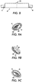
FIG. 8 provides a cross-sectional detail view taken through E-E of FIG. 7A.
FIGS. 9A, 9B and 9C provide schematic perspective views of the preferred embodiment of the invention.
DESCRIPTION
In general, the instant invention resolves and avoids the difficulties inherent in prior art by providing and supporting a notched member in the form of a centering notch 6A, 60A in the open insertion end 5A of the cylindrical member 1 that is to be installed against vertical plate 2 so as to be in communication with aperture 2A. In its basic embodiments, as illustrated in FIGS. 2 through 6, the holding structure of the centering device 6 takes the form of a bisecting brace or bracket with a center notch 6A installed in or forming part of the open insertion end 5A of the cylindrical member 1. As will be clear from review of the drawing figures, the bisecting linear portion of centering device 6 forms a dividing member which divides the open end 5A of cylindrical member 1 into portions in communication 5A′ with open side 6A′ of center notch 6A (as well as portions not in communication with open side 6A′). In its preferred embodiment, as illustrated in FIGS. 7A through 9C, the portion of the centering device 60 under (and not in communication with) the center notch 60A is substantially closed with slots 60C or other openings for fluid flow. The substantial closure of this half in the preferred embodiments prevents the operator from installing the coalescer on the wrong side of centering rod 4. This addition does not impede the fluid flow, nor limit the access to install.
The invention with its center notch 6A, 60A with an open side 6A′, 60A′ is shaped such that when the cylindrical member 1 is partially installed over centering rod 4 with centering rod 4 in the portion in communication 5A′ with open side 6A′, 60A′, the cylindrical member 1 can be rotated 180 degrees, causing the center notch 6A, 60A to engage and interface with the housing centering rod 4, automatically centering the cylindrical member 1 by raising up the far end (i.e., open end 5A) of the filter, separator, or coalescer (i.e., the cylindrical member 1) to align properly with the aperture 2A in the housing sealing plate 2.
As illustrated in FIG. 2, the apparatus of the invention in its basic embodiment can be simply and easily constructed by adding a dividing member (bisecting centering device/bracket 6) to open end 5A of cylindrical member 1 in the manner illustrated and previously described so as to form part of the holding structure for notch 6A. And, as will be noted in particular with reference to FIGS. 3A through 3B, appropriately shaped curved arms 6B matching the inner curvature and dimensions of cylindrical member 1 can preferably be included at either end of centering bracket 6 to aid in its incorporation into cylindrical member 1, to stabilize it in position, and for use in fastening it thereto (by welding, bolting or other means).
The initial insertion position is indicated in FIGS. 2 and 4, where it can be seen that the entire upper half of the open end 5A (i.e., the portions in communication 5A′ with open side 6A′) can be easily inserted over centering rod 4. However, at some point during the insertion process, the cylindrical member 1 is rotated around centering rod 4, bringing bisecting centering bracket 6 to its rotated (centering) position in end 5A of cylindrical member 1. (See, FIGS. 5 and 6). And, as previously stated, the act of rotation will elevate open end 5A to a position more properly aligned over aperture 2A in vertical plate 2 as centering bracket 6 is rotated to a position over centering rod 4. From this position, if centering rod 4 does not slide automatically into notch 6A, slight lateral adjustments can be used to nest centering rod 4 in the open side 6A′ of central notch 6A to more perfectly center and align open end 5A for sealing contact over aperture 2A in vertical plate 2.
In its preferred embodiment, the centering device 60 is advantageously formed as part of rim 1D and the portion of device 60 under its center notch 60A is formed as a closed portion 60B with a plurality of slots 60C or other openings too small to allow insertion of rod 4 therethrough, but providing sufficient openings to allow free flow of gases and fluids. Closed portion 60B prevents the operator from installing the cylindrical member with center notch 60A on the wrong side of the centering rod 4. In the preferred embodiment of the invention, the dividing member formed by edge 60B′ is tilted towards the open side 60A′ of notch 60A, so as to assist in sliding/ramping rod 4 and notch 60A into engagement. In addition, notch 60A is formed with a semi-circular portion matching the peripheral dimensions of rod 4 so as to better engage rod 4.
The parts of the various embodiments described and discussed above, and enumerated in the drawing figures, are as follows:
1—Cylindrical element or member
1A—Cylindrical element/member layer
1B—Cylindrical element/member layer
1C—O-ring
1D—Rim cap
1E—O-ring groove
2—Vertical seal plate
2A—Aperture
3—Access cover
4—Centering rod
5A—Open end
5A′—Portion in communication with open side
5B—Closed end
5C—Mounting Hole for Rod
6—Centering device
6A—Centering notch
6A′—Open side
6B—Curved arms
10—Tank
60—Centering device (preferred embodiment)
60A—Centering notch (preferred embodiment)
60A′—Open side (preferred embodiment)
60B—Closed portion (preferred embodiment)
60B′—Edge
60C—Slots
However, although the described advantages and features of the invention are advantageously provided through and using the embodiments previously illustrated and discussed, numerous variations are possible without deviating from and/or exceeding the spirit and scope of the invention. Moreover, various presently unforeseen or unanticipated alternatives, modifications, variations or improvements therein may be subsequently made by those skilled in the art which are also intended to be encompassed by the claims filed.

Claims (20)

We claim:
1. An apparatus having a self-centering element, comprising:
a housing including an interior wall;
an aperture in said wall, said aperture having a rod extending from its center;
a cylindrical element forming at least one of a filter, coalescer and separator, and having a self-centering element;
wherein said cylindrical element has a central axis and is adapted for placement with an open end over and in communication with the aperture; and
wherein said self-centering element comprises:
a notched member having an open side adapted for lateral capture of said rod,
a holding structure for holding said notched member in position proximate said central axis, said holding structure including a connector for connection of said self-centering element to the cylindrical element, and
wherein said holding structure includes a dividing member adapted to divide the open end of said cylindrical element into portions in communication with the open side and portions not in communication with said open side.
2. The apparatus of claim 1, wherein said connector is formed from one of
a member attached to the cylindrical element proximate said open end,
a member attached to a rim of the cylindrical element proximate said open end, and
a member forming a portion of the rim attached to the cylindrical element proximate said open end.
3. The apparatus of claim 1, wherein said dividing member is formed by a substantially linear element spanning the open end of the cylindrical element and having said notched member formed therein.
4. The apparatus of claim 1, wherein said dividing member is formed as a portion of the rim on the open end of the cylindrical element and has said notched member formed therein.
5. The apparatus of claim 1, wherein the portions not in communication with said open side are adapted to block insertion of said rod, but not flow of liquids or gases therethrough.
6. A method for providing and using a filter, coalescer or separator having a self-centering element, comprising:
providing a cylindrical element forming at least one of a filter, coalescer and separator, having a central axis and adapted for placement with an open end over and in communication with an aperture;
providing a self-centering element comprising
a notched member having an open side adapted for lateral capture of a rod,
a holding structure for holding said notched member in position proximate said central axis, said holding structure including a connector for connection of said self-centering element to the cylindrical element, and
wherein said holding structure includes a dividing member adapted to divide the open end of said cylindrical element into portions in communication with the open side and portions not in communication with said open side;
operationally positioning said self-centering element in the open end of said cylindrical element;
inserting said cylindrical element into a housing including an interior wall having an aperture with a rod extending from its center;
inserting the portion of said open end in communication with the open side of the notched member member over said rod; and
rotating said cylindrical element around its central axis and capturing said rod in the open side of said notched member.
7. The method of claim 6, wherein said connector is formed from one of
a member attached to the cylindrical element proximate said open end,
a member attached to a rim of the cylindrical element proximate said open end, and
a member forming a portion of the rim attached to the cylindrical element proximate said open end.
8. The method of claim 6, wherein said dividing member is formed by a substantially linear element spanning the open end of the cylindrical element and having said notched member formed therein.
9. The method of claim 6, wherein said dividing member is formed as a portion of the rim on the open end of the cylindrical element and has said notched member formed therein.
10. The method of claim 6, wherein the portions not in communication with said open side are adapted to block insertion of said rod, but not flow of liquids or gases therethrough.
11. Apparatus having a filter, coalescer or separator adapted for placement with an open end over and in communication with an aperture, which aperture has a rod extending from its center for use in connection of said filter, coalescer or separator in position over said aperture, said apparatus comprising:
a housing including a wall with an aperture in said wall, said aperture having a rod extending from its center for use in connection of a cylindrical element in position over said aperture;
a cylindrical element forming at least one of a filter, coalescer and separator, and having a central axis and an open end;
a self-centering element having a notched member, said notched member having an open side adapted for lateral capture of said rod;
a holding structure for holding said notched member in position proximate said central axis, said holding structure including a connector for connection of said self-centering element to the cylindrical element; and
wherein said holding structure includes a dividing member adapted to divide the open end of said cylindrical element into portions in communication with the open side and portions not in communication with said open side.
12. The apparatus of claim 11, wherein said connector is formed from one of
a member attached to the cylindrical element proximate said open end,
a member attached to a rim of the cylindrical element proximate said open end, and
a member forming a portion of the rim attached to the cylindrical element proximate said open end.
13. The apparatus of claim 11, wherein said dividing member is formed by a substantially linear element spanning the open end of the cylindrical element and having said notched member formed therein.
14. The apparatus of claim 11, wherein said dividing member is formed as a portion of the rim on the open end of the cylindrical element and has said notched member formed therein.
15. The apparatus of claim 11, wherein the portions not in communication with said open side are adapted to block insertion of said rod, but not flow of liquids or gases therethrough.
16. The apparatus of claim 2, wherein said dividing member is formed by a substantially linear element spanning the open end of the cylindrical element and having said notched member formed therein.
17. The apparatus of claim 2, wherein said dividing member is formed as a portion of the rim on the open end of the cylindrical element and has said notched member formed therein.
18. The apparatus of claim 17, wherein the portions not in communication with said open side are adapted to block insertion of said rod, but not flow of liquids or gases therethrough.
19. The apparatus of claim 1, wherein the dividing member is sloped in order to ramp said rod towards the open side of the notch when said open side faces downward.
20. The apparatus of claim 18, wherein the dividing member is sloped in order to ramp said rod towards the open side of the notch when said open side faces downward.
US12/462,842 2008-08-08 2009-08-10 Self-centering filters, coalescers and separators Active 2031-03-04 US8900452B2 (en)

Priority Applications (1)

Application Number Priority Date Filing Date Title
US12/462,842 US8900452B2 (en) 2008-08-08 2009-08-10 Self-centering filters, coalescers and separators

Applications Claiming Priority (2)

Application Number Priority Date Filing Date Title
US18833608P 2008-08-08 2008-08-08
US12/462,842 US8900452B2 (en) 2008-08-08 2009-08-10 Self-centering filters, coalescers and separators

Publications (2)

Publication Number Publication Date
US20100116350A1 US20100116350A1 (en) 2010-05-13
US8900452B2 true US8900452B2 (en) 2014-12-02

Family

ID=41664133

Family Applications (1)

Application Number Title Priority Date Filing Date
US12/462,842 Active 2031-03-04 US8900452B2 (en) 2008-08-08 2009-08-10 Self-centering filters, coalescers and separators

Country Status (3)

Country Link
US (1) US8900452B2 (en)
CA (1) CA2733022A1 (en)
WO (1) WO2010016948A2 (en)

Citations (2)

* Cited by examiner, † Cited by third party
Publication number Priority date Publication date Assignee Title
US4209310A (en) * 1975-07-28 1980-06-24 Donaldson Company, Inc. Filter element mounting mechanism
US6372133B1 (en) * 1998-06-27 2002-04-16 Sartorius Ag Multiple filter housing with filter element locking device

Family Cites Families (4)

* Cited by examiner, † Cited by third party
Publication number Priority date Publication date Assignee Title
US5667679A (en) * 1996-06-24 1997-09-16 Graver Chemical Company Filter having a filter element quick-disconnect mount
US6019229A (en) * 1997-12-18 2000-02-01 Fleetguard, Inc. Self-centering, floating retainer for spin-on filter
US7056364B2 (en) * 2003-12-16 2006-06-06 Chun Hsiang Wang Securing seat for holding filtering cylinder of a dust collector
US20070266681A1 (en) * 2006-05-19 2007-11-22 Bha Group, Inc. Filter mounting structure and method

Patent Citations (2)

* Cited by examiner, † Cited by third party
Publication number Priority date Publication date Assignee Title
US4209310A (en) * 1975-07-28 1980-06-24 Donaldson Company, Inc. Filter element mounting mechanism
US6372133B1 (en) * 1998-06-27 2002-04-16 Sartorius Ag Multiple filter housing with filter element locking device

Also Published As

Publication number Publication date
WO2010016948A3 (en) 2010-06-03
CA2733022A1 (en) 2010-02-11
WO2010016948A2 (en) 2010-02-11
US20100116350A1 (en) 2010-05-13

Similar Documents

Publication Publication Date Title
US8128817B2 (en) Liquid filter suitable for motor vehicles
US9011683B2 (en) Filter cartridge centering device
US6896803B2 (en) Filter apparatus and associated method
EP3402689B1 (en) Closure assembly for fuel-tank filler neck
RU2734392C2 (en) Hollow filtration element, in particular, for gas filtration
JP6200097B2 (en) Valve case mounting structure
CN110430930B (en) Filter Assemblies with Top Ribbed Internal Filter Elements
US8349061B2 (en) Combination relief valve and drainage mechanism requiring inserted element to permit drainage in a coalescer system
US9370998B2 (en) Fuel filler systems and methods of assembling same
US20170043285A1 (en) Oil-filter assembly
US20230264121A1 (en) Filter element locking mechanism
JP5650987B2 (en) Fuel tank
US7946624B2 (en) Mounting structures for piping members
US8900452B2 (en) Self-centering filters, coalescers and separators
CN102549315A (en) Vessel, in particular pressure vessel
US11318400B2 (en) Top and bottom loaded filter and locking mechanism
CN116099477A (en) End Plates with Guide Features
EP3281006A1 (en) Sorbent tube apparatus
US20210322905A1 (en) Integrated multifunctional endcap seal member
US20200108337A1 (en) Liquid Filtering Device
CN112295304B (en) Manifold assembly and method of use
US11517839B2 (en) Filter arrangement
CN104755741A (en) device for delivering fuel
EP3813981B1 (en) Filter device and method for installing such filter device
JP4819660B2 (en) Relief valve

Legal Events

Date Code Title Description
STCF Information on status: patent grant

Free format text: PATENTED CASE

FEPP Fee payment procedure

Free format text: MAINTENANCE FEE REMINDER MAILED (ORIGINAL EVENT CODE: REM.)

FEPP Fee payment procedure

Free format text: SURCHARGE FOR LATE PAYMENT, SMALL ENTITY (ORIGINAL EVENT CODE: M2554); ENTITY STATUS OF PATENT OWNER: SMALL ENTITY

MAFP Maintenance fee payment

Free format text: PAYMENT OF MAINTENANCE FEE, 4TH YR, SMALL ENTITY (ORIGINAL EVENT CODE: M2551); ENTITY STATUS OF PATENT OWNER: SMALL ENTITY

Year of fee payment: 4

FEPP Fee payment procedure

Free format text: MAINTENANCE FEE REMINDER MAILED (ORIGINAL EVENT CODE: REM.); ENTITY STATUS OF PATENT OWNER: SMALL ENTITY

FEPP Fee payment procedure

Free format text: 7.5 YR SURCHARGE - LATE PMT W/IN 6 MO, SMALL ENTITY (ORIGINAL EVENT CODE: M2555); ENTITY STATUS OF PATENT OWNER: SMALL ENTITY

MAFP Maintenance fee payment

Free format text: PAYMENT OF MAINTENANCE FEE, 8TH YR, SMALL ENTITY (ORIGINAL EVENT CODE: M2552); ENTITY STATUS OF PATENT OWNER: SMALL ENTITY

Year of fee payment: 8