US8899783B1 - LED optics for bulbs and luminaires - Google Patents
LED optics for bulbs and luminaires Download PDFInfo
- Publication number
- US8899783B1 US8899783B1 US13/705,684 US201213705684A US8899783B1 US 8899783 B1 US8899783 B1 US 8899783B1 US 201213705684 A US201213705684 A US 201213705684A US 8899783 B1 US8899783 B1 US 8899783B1
- Authority
- US
- United States
- Prior art keywords
- bulb
- led
- light
- leds
- surrounding
- Prior art date
- Legal status (The legal status is an assumption and is not a legal conclusion. Google has not performed a legal analysis and makes no representation as to the accuracy of the status listed.)
- Expired - Fee Related
Links
Images


Classifications
-
- G—PHYSICS
- G02—OPTICS
- G02B—OPTICAL ELEMENTS, SYSTEMS OR APPARATUS
- G02B6/00—Light guides; Structural details of arrangements comprising light guides and other optical elements, e.g. couplings
- G02B6/0001—Light guides; Structural details of arrangements comprising light guides and other optical elements, e.g. couplings specially adapted for lighting devices or systems
- G02B6/0011—Light guides; Structural details of arrangements comprising light guides and other optical elements, e.g. couplings specially adapted for lighting devices or systems the light guides being planar or of plate-like form
- G02B6/0066—Light guides; Structural details of arrangements comprising light guides and other optical elements, e.g. couplings specially adapted for lighting devices or systems the light guides being planar or of plate-like form characterised by the light source being coupled to the light guide
- G02B6/0073—Light emitting diode [LED]
-
- F—MECHANICAL ENGINEERING; LIGHTING; HEATING; WEAPONS; BLASTING
- F21—LIGHTING
- F21V—FUNCTIONAL FEATURES OR DETAILS OF LIGHTING DEVICES OR SYSTEMS THEREOF; STRUCTURAL COMBINATIONS OF LIGHTING DEVICES WITH OTHER ARTICLES, NOT OTHERWISE PROVIDED FOR
- F21V5/00—Refractors for light sources
- F21V5/04—Refractors for light sources of lens shape
-
- G—PHYSICS
- G02—OPTICS
- G02B—OPTICAL ELEMENTS, SYSTEMS OR APPARATUS
- G02B6/00—Light guides; Structural details of arrangements comprising light guides and other optical elements, e.g. couplings
- G02B6/0001—Light guides; Structural details of arrangements comprising light guides and other optical elements, e.g. couplings specially adapted for lighting devices or systems
- G02B6/0005—Light guides; Structural details of arrangements comprising light guides and other optical elements, e.g. couplings specially adapted for lighting devices or systems the light guides being of the fibre type
- G02B6/0006—Coupling light into the fibre
-
- F—MECHANICAL ENGINEERING; LIGHTING; HEATING; WEAPONS; BLASTING
- F21—LIGHTING
- F21K—NON-ELECTRIC LIGHT SOURCES USING LUMINESCENCE; LIGHT SOURCES USING ELECTROCHEMILUMINESCENCE; LIGHT SOURCES USING CHARGES OF COMBUSTIBLE MATERIAL; LIGHT SOURCES USING SEMICONDUCTOR DEVICES AS LIGHT-GENERATING ELEMENTS; LIGHT SOURCES NOT OTHERWISE PROVIDED FOR
- F21K9/00—Light sources using semiconductor devices as light-generating elements, e.g. using light-emitting diodes [LED] or lasers
- F21K9/20—Light sources comprising attachment means
- F21K9/23—Retrofit light sources for lighting devices with a single fitting for each light source, e.g. for substitution of incandescent lamps with bayonet or threaded fittings
-
- F—MECHANICAL ENGINEERING; LIGHTING; HEATING; WEAPONS; BLASTING
- F21—LIGHTING
- F21K—NON-ELECTRIC LIGHT SOURCES USING LUMINESCENCE; LIGHT SOURCES USING ELECTROCHEMILUMINESCENCE; LIGHT SOURCES USING CHARGES OF COMBUSTIBLE MATERIAL; LIGHT SOURCES USING SEMICONDUCTOR DEVICES AS LIGHT-GENERATING ELEMENTS; LIGHT SOURCES NOT OTHERWISE PROVIDED FOR
- F21K9/00—Light sources using semiconductor devices as light-generating elements, e.g. using light-emitting diodes [LED] or lasers
- F21K9/60—Optical arrangements integrated in the light source, e.g. for improving the colour rendering index or the light extraction
- F21K9/61—Optical arrangements integrated in the light source, e.g. for improving the colour rendering index or the light extraction using light guides
-
- F—MECHANICAL ENGINEERING; LIGHTING; HEATING; WEAPONS; BLASTING
- F21—LIGHTING
- F21V—FUNCTIONAL FEATURES OR DETAILS OF LIGHTING DEVICES OR SYSTEMS THEREOF; STRUCTURAL COMBINATIONS OF LIGHTING DEVICES WITH OTHER ARTICLES, NOT OTHERWISE PROVIDED FOR
- F21V7/00—Reflectors for light sources
-
- G—PHYSICS
- G02—OPTICS
- G02B—OPTICAL ELEMENTS, SYSTEMS OR APPARATUS
- G02B6/00—Light guides; Structural details of arrangements comprising light guides and other optical elements, e.g. couplings
- G02B6/0001—Light guides; Structural details of arrangements comprising light guides and other optical elements, e.g. couplings specially adapted for lighting devices or systems
- G02B6/0005—Light guides; Structural details of arrangements comprising light guides and other optical elements, e.g. couplings specially adapted for lighting devices or systems the light guides being of the fibre type
- G02B6/001—Light guides; Structural details of arrangements comprising light guides and other optical elements, e.g. couplings specially adapted for lighting devices or systems the light guides being of the fibre type the light being emitted along at least a portion of the lateral surface of the fibre
-
- G—PHYSICS
- G02—OPTICS
- G02B—OPTICAL ELEMENTS, SYSTEMS OR APPARATUS
- G02B6/00—Light guides; Structural details of arrangements comprising light guides and other optical elements, e.g. couplings
- G02B6/0001—Light guides; Structural details of arrangements comprising light guides and other optical elements, e.g. couplings specially adapted for lighting devices or systems
- G02B6/0011—Light guides; Structural details of arrangements comprising light guides and other optical elements, e.g. couplings specially adapted for lighting devices or systems the light guides being planar or of plate-like form
- G02B6/0013—Means for improving the coupling-in of light from the light source into the light guide
- G02B6/0023—Means for improving the coupling-in of light from the light source into the light guide provided by one optical element, or plurality thereof, placed between the light guide and the light source, or around the light source
- G02B6/003—Lens or lenticular sheet or layer
-
- G—PHYSICS
- G02—OPTICS
- G02B—OPTICAL ELEMENTS, SYSTEMS OR APPARATUS
- G02B6/00—Light guides; Structural details of arrangements comprising light guides and other optical elements, e.g. couplings
- G02B6/0001—Light guides; Structural details of arrangements comprising light guides and other optical elements, e.g. couplings specially adapted for lighting devices or systems
- G02B6/0011—Light guides; Structural details of arrangements comprising light guides and other optical elements, e.g. couplings specially adapted for lighting devices or systems the light guides being planar or of plate-like form
- G02B6/0013—Means for improving the coupling-in of light from the light source into the light guide
- G02B6/0023—Means for improving the coupling-in of light from the light source into the light guide provided by one optical element, or plurality thereof, placed between the light guide and the light source, or around the light source
- G02B6/0031—Reflecting element, sheet or layer
-
- G—PHYSICS
- G02—OPTICS
- G02B—OPTICAL ELEMENTS, SYSTEMS OR APPARATUS
- G02B6/00—Light guides; Structural details of arrangements comprising light guides and other optical elements, e.g. couplings
- G02B6/0001—Light guides; Structural details of arrangements comprising light guides and other optical elements, e.g. couplings specially adapted for lighting devices or systems
- G02B6/0011—Light guides; Structural details of arrangements comprising light guides and other optical elements, e.g. couplings specially adapted for lighting devices or systems the light guides being planar or of plate-like form
- G02B6/0033—Means for improving the coupling-out of light from the light guide
- G02B6/0035—Means for improving the coupling-out of light from the light guide provided on the surface of the light guide or in the bulk of it
- G02B6/0045—Means for improving the coupling-out of light from the light guide provided on the surface of the light guide or in the bulk of it by shaping at least a portion of the light guide
-
- G—PHYSICS
- G02—OPTICS
- G02B—OPTICAL ELEMENTS, SYSTEMS OR APPARATUS
- G02B6/00—Light guides; Structural details of arrangements comprising light guides and other optical elements, e.g. couplings
- G02B6/0001—Light guides; Structural details of arrangements comprising light guides and other optical elements, e.g. couplings specially adapted for lighting devices or systems
- G02B6/0011—Light guides; Structural details of arrangements comprising light guides and other optical elements, e.g. couplings specially adapted for lighting devices or systems the light guides being planar or of plate-like form
- G02B6/0075—Arrangements of multiple light guides
-
- F—MECHANICAL ENGINEERING; LIGHTING; HEATING; WEAPONS; BLASTING
- F21—LIGHTING
- F21Y—INDEXING SCHEME ASSOCIATED WITH SUBCLASSES F21K, F21L, F21S and F21V, RELATING TO THE FORM OR THE KIND OF THE LIGHT SOURCES OR OF THE COLOUR OF THE LIGHT EMITTED
- F21Y2115/00—Light-generating elements of semiconductor light sources
- F21Y2115/10—Light-emitting diodes [LED]
-
- G—PHYSICS
- G02—OPTICS
- G02B—OPTICAL ELEMENTS, SYSTEMS OR APPARATUS
- G02B6/00—Light guides; Structural details of arrangements comprising light guides and other optical elements, e.g. couplings
- G02B6/0001—Light guides; Structural details of arrangements comprising light guides and other optical elements, e.g. couplings specially adapted for lighting devices or systems
- G02B6/0011—Light guides; Structural details of arrangements comprising light guides and other optical elements, e.g. couplings specially adapted for lighting devices or systems the light guides being planar or of plate-like form
- G02B6/0066—Light guides; Structural details of arrangements comprising light guides and other optical elements, e.g. couplings specially adapted for lighting devices or systems the light guides being planar or of plate-like form characterised by the light source being coupled to the light guide
- G02B6/0068—Arrangements of plural sources, e.g. multi-colour light sources
Definitions
- the present invention provides light bulbs and luminaires that provide radially directed lighting that can be used for indirect surface illumination, and can be used in shallow and or in large diameter fixture applications; as also a bulb that is a simple and direct method for converting and or retrofitting a lamp or ceiling socket to be a beam directing accent light luminaire; and also a bulb or luminaire that provides multiple types of illumination separately or simultaneously.
- FIG. 1 is a plan view diagram of an LED lighting component ring that can be used in light bulbs or luminaires;
- FIG. 1A is an isometric view of an LED lighting component ring similar to that shown in FIG. 1 ;
- FIG. 1B is a plan view diagram of a lighting system that incorporates the LED lighting component ring described in FIG. 1 ;
- FIGS. 1C and 1D are cross-sectional diagrams of the lighting system as described in connection with FIG. 1A ;
- FIG. 1E is a diagrammatic plan view of a matrix of lighting component rings as shown and described in connection with FIG. 1 ;
- FIGS. 2 , 2 A, and 2 B are diagrammatic views of existing technology currently used in LED light bulbs
- FIG. 2C is a diagrammatic side sectional view of an LED light bulb containing a ring of LEDs surrounded by light concentrating lenses;
- FIGS. 2D and 2E are a combined section view and a top view of an LED light bulb having a similar function to that shown in FIG. 2C ;
- FIG. 3 is a sectional side view diagram of an LED light bulb that can project a variably directional light beam
- FIG. 3A is a cutaway isometric view of the light bulb illustrated in FIG. 3 further showing ventilation of heat and therefore cooling of the bulb;
- FIG. 3B is a side sectional view of an LED light bulb similar in function to that shown in FIGS. 3 and 3A containing multiple LEDs;
- FIG. 3C is a side sectional view illustrating a lamp utilizing an LED bulb having a similar function to those shown in FIGS. 3 through 3B ;
- FIG. 3D is a cross-sectional view taken through an architectural plane showing the function of three LED bulbs as illustrated in FIGS. 3 through 3B ;
- FIG. 4 is a three dimensional diagram of a three dimensional diagram of a lighting component assembly similar in function to the lighting component ring described in FIG. 1 ;
- FIG. 4A is a cross sectional view of a lighting component assembly similar to that shown in FIG. 4 ;
- FIG. 4B is a cross sectional view of a lighting component assembly having different light collection optics than the lighting component assembly shown in FIG. 4A ;
- FIG. 4C is a plan view of a lighting component assembly having a variation in the lighting function to the lighting component assembly shown in FIG. 4 .
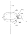
- FIG. 1 is a plan view of a lighting component ring LR that can be used in light bulbs or lumenaires comprising a ring component RC surrounding a central axis AX (fabricated from solid material such as plastic or metal) onto the outer surface of which light emitting diodes LEDS are periodically disposed. At least one of the LEDs LEDs can be at least partially surrounded by a light collecting optic such as a focusing reflector FR, for the purpose of projecting beam FB outwardly surrounding radial axis RA beam and away from lighting component ring FR.
- Lighting component ring OR can be designed and fabricated as an oval or a polygon in plan such as a square or hexagon.
- lighting component ring LR can be applied as (or be substituted for) multibeam projectors described in U.S. Pat. No. 7,677,760, which is incorporated herein by reference.
- FIG. 1A is a three dimensional view of lighting component ring LR shown in FIG. 1 for explanation and graphic purposes. Only one of the LEDs LED is shown to utilize a focusing reflector FR to collect and project rays ER emanating from one of the LEDs LED as a focused beam FB away from lighting component ring LR.
- FIG. 1B is a plan view of a lighting system configuration LS, incorporating optical ring OR, that at least partially surrounds and incorporates the function of lighting ring component LR as illustrated in FIGS. 1 and 1A .
- Optical ring OR is shown to be substantially concentric to lighting ring LR.
- light component ring OR can be an oval or a polygon in plan such as a square or hexagon and can be congruent to the lighting component when ring LR is of a similar shape.
- optical ring OR is graphically divided into a right portion ORR which is shaped in section to be an optical window comprising prismatic elements and having a refractive function such as bending, focusing, expanding or diffusing typical beam FB received from the periodically disposed LEDs LED mounted to ring RC of lighting component ring OR which is either a warped or flat plane in section, having the combined function of a light guide and a refracting function.
- ORR which is shaped in section to be an optical window comprising prismatic elements and having a refractive function such as bending, focusing, expanding or diffusing typical beam FB received from the periodically disposed LEDs LED mounted to ring RC of lighting component ring OR which is either a warped or flat plane in section, having the combined function of a light guide and a refracting function.
- Each portion, ORR and ORL can be continuous or as illustrated can be radially divided into segments as, each segment of which can have a different optical function, in this embodiment two types of lighting functions (beam patterns) are achieved by respective alternating segments as of optical ring portions ORR or ORL (as further described in connection with FIGS. 1C and 1D ).
- FIGS. 1C and 1D are cross-sectional diagrams of the lighting system LS as illustrated in FIG. 2A .
- the refracting function of segment AS of right ring portion ORR of FIG. 1C is to bend beam FB projected by reflector FR at an angle downward as beam D (relative to the drawn figure).
- the refracting function of segment AS of right ring portion ORR of FIG. 1D is to bend beam FB projected by reflector FR at an upward angle as beam IB (relative to the drawn figure).
- segment AS of left ring portions ORL of FIG. 1C are to allow a part of beam FB to pass through and a part of beam FB to be refracted upwardly as combined CB (relative to the drawn figure).
- segment AS of left ring portion ORL of FIG. 1D is to allow apart of beam FB to pass through as beam RB and a part of beam FB to be refracted downward as beam DB (relative to the drawn figure).
- the variations and alternations of segments AS of lighting systems provide multiple light distribution patterns for the lighting system. By on/off switches or dimming of LEDs a single or multiple distribution patterns could be achieved.
- FIG. 1D further shows a bulb base BA illustrating that the configurations in FIGS. 1 through 1D can be incorporated into LED light bulbs as illustrated in FIGS. 2C through 2E .
- FIG. 1E is a plan view diagram of a matrix MA of lighting rings LR (which are described in connection with FIGS. 1 and 1B ) positioned on the intersection CE of a matrix of axes S.
- the lighting rings are connected by modified light guides LG which are each parallel to or surround an axis AX.
- the LEDs LED are so disposed about the lighting rings LR to project light directly into an end of an associated light guide LG.
- a collecting optic such as a reflector FR, that is connected to the lighting component ring LR or is fabricated integral to the light guide LG, can be employed to increase the intensity of the light entering the light guide LG, and as in the light guide LG comprising internally refracting prisms RR increasing the intensity of the light exiting the ring, shown as rays ER.
- Rotational arrow RA describes that in some embodiments light guides via a hearing mechanism M can be made to rotate about axis AX so as to change the direction of the rays ER.
- connected light guides LG can project or emanate light include ones that contain refracting or reflecting particles, ones that taper TG radiating rays SR, ones that allow to pass through an exit beam EB or ones that have a moveable reflector RE to change the direction of exit beam EB.
- Light guides LG can be the primary structure connecting lighting ring FR.
- Structural hubs HU and struts ST can be employed to create three dimensional structures such as tetrahedrons.
- Hub H can comprise LEDs LED and struts ST can function as light guides.
- FIGS. 2 , 2 A, and 2 B are a three dimensional diagram, a side view diagram and a top view diagram of components and configurations of existing LED light bulb technology for creating single function non-concentrated light distribution similar to that of a filament type or compact fluorescent type lamp shaped bulb.
- the components for this technology are as follows: LEDs LED radiating substantially a lambertian light distribution RR, mounted to a heat sink assembly HS, the heat sink assembly HS enclosed within a bulb enclosure BE. The base of the bulb is not shown.
- FIG. 2C is a combined side view section diagram of an LED light bulb containing a ring of outwardly facing LEDs LED mounted to a ring-like heat sink. configuration HS.
- a bulb envelope BE Surrounding and enclosing the ring of LEDs LED and its associated heat sink HS is a bulb envelope BE.
- Integrally formed (molded) or fabricated onto the bulb envelope BE is a ring of light concentrating lenses FL, each disposed and positioned to collect and project rays RR emanating from its associated LED as a concentrated beam CB outwardly and away from the central axis AX and from the bulb LB.
- a partial view of base BD can comprise electrical and or electronic hardware and can be a screw, pin, or prefocus male type socket.
- FIGS. 2D and 2E are a combined side view section and a top view section of an LED light bulb LB similar in function to the light bulb illustrated in FIG. 2C differing in that the bulb enclosure BE comprises a ring of outwardly projecting reflectors FR and or reflector FR-refractor FL combined. Formed or fabricated into bulb envelope BE and disposed so as to collect and project rays RR emanating from an associated LED LED as a concentrated beam outwardly and away from bulb along and surrounding a radial axis AR.
- FIG. 2E also illustrates refractor SR which comprises prismatic element which spreads concentrated rays of beam SR.
- Refractor FR can be located immediately in front of collecting reflectors RR, attached to or part of bulb envelope BE or be disposed at a distance as part of a luminaire that at least partially surrounds bulb LB.
- FIG. 3 is a side view sectional diagram of an LED light bulb LB that can project a variably directional beam VB.
- Beam VB is produced by an optical configuration having a light emitting diode LED disposed within the bulb envelope BE and a concentrating optic such as reflector RFat least partially surrounding the LED LED. This optical configuration is mounted to an axle XL which spans between and passed through at least one wall of the bulb envelope BE at a pivot point PP located on the transverse axis TA of bulb BE.
- Bulb base BL can be of a screw, pin, prefocus or any other type standard or custom bulb envelope be it clear or diffuse or comprise prismatic elements.
- Bulb LB comprises a substantially spherical bulb envelope BE which is fabricated from transparent or translucent material such as glass or plastic or other material that allows for the passage of light, and includes a bulb base BS which is connected to the bulb envelope BE via a bearing sleeve BS (not detailed) so that the bulb envelope can rotate in respect to the bulb base about axis VA as illustrated by arrow AA.
- the combined rotation of the bulb envelope BE around its axis VA and the rotation of heat sink HS around transverse axis TA provides for at least a minimum of 270° of spherical freedom for manually directing beam VB.
- FIG. 3A is a cutaway isometric view of the light bulb illustrated in FIG. 3 further showing that axle XL is a tube the ends of which are disposed within holes H located in bulb envelope BE located substantially about axis TA allowing airflow FL to evacuate from the bulb envelope lowering the temperature of heat sink HS.
- FIG. 3B is a side view section diagram of an LED light bulb similar in function to that shown in FIGS. 3 and 3A differing in that light produced by the bulb LB is derived from multiple LEDs LED and is in the other form of a flood beam FB.
- at least one of the LEDs LED can be at least partially surrounded by a light modifying optic such as a focusing lens, focusing reflector, or diffuser.
- FIG. 3C is a side view diagram illustrating the use of a light bulb LB (similar to that shown in FIGS. 3 , 3 A, and 3 B) in a table or floor lamp LA that can provide a beam B for reading or any other lighting application.
- a light bulb LB similar to that shown in FIGS. 3 , 3 A, and 3 B
- FIG. 3D is a cross-sectional diagram taken through a ceiling (or other architectural plane) CR showing three light bulbs LB 1 , LB 2 , and LB 3 mounted within typical light receptacle JB, projecting their respective beams B 1 , B 2 , and B 3 in various directions.
- FIG. 4 is a three dimensional diagram of a lighting component assembly LA similar in function to the lighting component ring LR described in FIG. 1 , differing in that the LEDs LED are mounted to a pc board CB instead of a ring, their light emanating in the direction of the central axis CA which is substantially perpendicular to pc board CB. At least one of the LEDs LED is at least partially surrounded by a light collecting optic such as a ellipsoidal or parabolic reflector FR, which collects and projects light emanating from the LED as a focused beam FB in the direction of and at least partially surrounding beam axis BA away from central axis CA.
- Lighting component assembly LA can in some embodiments (such as the lighting system configuration that is discussed in connection with FIG. 1B ) be as to substitute for lighting component ring LR.
- FIG. 4A is a cross sectional diagram of the lighting component assembly shown in FIG. 4 illustrating light collecting optic FR collecting and reflecting rays RR emanating from LED LED as concentrated beam FB away from central axis CA.
- FIG. 4B is a cross sectional diagram of a lighting component assembly LA similar to that shown in FIG. 4A differing in that the light collecting optic combines at least a segment of a concentrating lens FL and at least a segment of a reflector FR, the combined function of which can collect and project substantially the entire flux of radiant rays emanating from the LED LED.
- FIG. 4C is a planar view of a light component assembly LA similar in structure and function as that shown in FIGS. 4 thru 4 B, that further includes a continuous reflector RC that can collect and project rays emanating from at least 2 LEDs as a continuous radial beam CB outwardly and away from central axis CA.
- FIG. 4C further illustrates refracting ring CR widening focused beams FB as spread beams SC that can radiate and mix with adjacent spread beams as overlapping beam OB.
Landscapes
- Physics & Mathematics (AREA)
- Optics & Photonics (AREA)
- Engineering & Computer Science (AREA)
- General Physics & Mathematics (AREA)
- Microelectronics & Electronic Packaging (AREA)
- General Engineering & Computer Science (AREA)
- Non-Portable Lighting Devices Or Systems Thereof (AREA)
- Fastening Of Light Sources Or Lamp Holders (AREA)
- Arrangement Of Elements, Cooling, Sealing, Or The Like Of Lighting Devices (AREA)
Abstract
Description
Claims (20)
Priority Applications (2)
| Application Number | Priority Date | Filing Date | Title |
|---|---|---|---|
| US13/705,684 US8899783B1 (en) | 2011-12-05 | 2012-12-05 | LED optics for bulbs and luminaires |
| US14/556,918 US9804321B1 (en) | 2011-12-05 | 2014-12-01 | LED optics for bulbs and luminaires |
Applications Claiming Priority (3)
| Application Number | Priority Date | Filing Date | Title |
|---|---|---|---|
| US201161630119P | 2011-12-05 | 2011-12-05 | |
| US201261741173P | 2012-07-13 | 2012-07-13 | |
| US13/705,684 US8899783B1 (en) | 2011-12-05 | 2012-12-05 | LED optics for bulbs and luminaires |
Related Child Applications (1)
| Application Number | Title | Priority Date | Filing Date |
|---|---|---|---|
| US14/556,918 Continuation US9804321B1 (en) | 2011-12-05 | 2014-12-01 | LED optics for bulbs and luminaires |
Publications (1)
| Publication Number | Publication Date |
|---|---|
| US8899783B1 true US8899783B1 (en) | 2014-12-02 |
Family
ID=51948289
Family Applications (2)
| Application Number | Title | Priority Date | Filing Date |
|---|---|---|---|
| US13/705,684 Expired - Fee Related US8899783B1 (en) | 2011-12-05 | 2012-12-05 | LED optics for bulbs and luminaires |
| US14/556,918 Expired - Fee Related US9804321B1 (en) | 2011-12-05 | 2014-12-01 | LED optics for bulbs and luminaires |
Family Applications After (1)
| Application Number | Title | Priority Date | Filing Date |
|---|---|---|---|
| US14/556,918 Expired - Fee Related US9804321B1 (en) | 2011-12-05 | 2014-12-01 | LED optics for bulbs and luminaires |
Country Status (1)
| Country | Link |
|---|---|
| US (2) | US8899783B1 (en) |
Cited By (7)
| Publication number | Priority date | Publication date | Assignee | Title |
|---|---|---|---|---|
| US20140226330A1 (en) * | 2013-02-08 | 2014-08-14 | Samsung Electronics Co., Ltd. | Light emitting devices and methods of manufacturing and controlling thereof |
| CN104930374A (en) * | 2015-06-15 | 2015-09-23 | 深圳绿米联创科技有限公司 | Annular light-emitting device |
| US9447930B1 (en) * | 2014-03-28 | 2016-09-20 | Jerome H. Simon | Multi function LED light bulb and lumenairs with interchangeable optical components |
| US10036534B2 (en) * | 2015-04-02 | 2018-07-31 | Abl Ip Holding Llc | High bay light fixture |
| US20200092961A1 (en) * | 2018-09-14 | 2020-03-19 | Xiamen Eco Lighting Co. Ltd. | Led ligtht apparatus |
| US10876709B2 (en) | 2016-02-18 | 2020-12-29 | Colordyne Limited | Lighting device with light conductor and spherically curved, rotatable lens/reflector unit with adjustable focus |
| WO2024143775A1 (en) * | 2022-12-26 | 2024-07-04 | 주식회사 제이시스메디칼 | Ipl device for skin care using led light source |
Families Citing this family (1)
| Publication number | Priority date | Publication date | Assignee | Title |
|---|---|---|---|---|
| NL2034575B1 (en) * | 2023-04-14 | 2024-10-21 | Epeon | Luminaire and system including the same |
Citations (7)
| Publication number | Priority date | Publication date | Assignee | Title |
|---|---|---|---|---|
| US3739169A (en) * | 1970-09-01 | 1973-06-12 | W Weinreich | Panoramic light emitter for warning lights |
| US6443604B1 (en) * | 1997-05-30 | 2002-09-03 | Murray Rudenberg | Remotely activated high-candle power illumination |
| US20050146884A1 (en) * | 2004-01-07 | 2005-07-07 | Goodrich Hella Aerospace Lighting Systems Gmbh | Light, particularly a warning light, for a vehicle |
| US20070025121A1 (en) * | 2003-07-28 | 2007-02-01 | Takamasa Harada | Surface light source |
| US20080247173A1 (en) * | 2007-04-09 | 2008-10-09 | Danek Joshua M | Lens system for led lights |
| US20100259929A1 (en) * | 2009-03-25 | 2010-10-14 | Marc Henri | LED beacon obstruction lighting system |
| US20110267801A1 (en) * | 2010-03-03 | 2011-11-03 | Cree, Inc. | Led lamp or bulb with remote phosphor and diffuser configuration with enhanced scattering properties |
Family Cites Families (4)
| Publication number | Priority date | Publication date | Assignee | Title |
|---|---|---|---|---|
| US6598996B1 (en) * | 2001-04-27 | 2003-07-29 | Pervaiz Lodhie | LED light bulb |
| US6948830B1 (en) * | 2004-01-14 | 2005-09-27 | Petrick John T | Dual beacon obstruction lighting system |
| US8461748B1 (en) * | 2010-04-29 | 2013-06-11 | Lights Of America, Inc. | LED lamp |
| US8752974B2 (en) * | 2011-03-16 | 2014-06-17 | Barry Leibowitz | Low glow |
-
2012
- 2012-12-05 US US13/705,684 patent/US8899783B1/en not_active Expired - Fee Related
-
2014
- 2014-12-01 US US14/556,918 patent/US9804321B1/en not_active Expired - Fee Related
Patent Citations (7)
| Publication number | Priority date | Publication date | Assignee | Title |
|---|---|---|---|---|
| US3739169A (en) * | 1970-09-01 | 1973-06-12 | W Weinreich | Panoramic light emitter for warning lights |
| US6443604B1 (en) * | 1997-05-30 | 2002-09-03 | Murray Rudenberg | Remotely activated high-candle power illumination |
| US20070025121A1 (en) * | 2003-07-28 | 2007-02-01 | Takamasa Harada | Surface light source |
| US20050146884A1 (en) * | 2004-01-07 | 2005-07-07 | Goodrich Hella Aerospace Lighting Systems Gmbh | Light, particularly a warning light, for a vehicle |
| US20080247173A1 (en) * | 2007-04-09 | 2008-10-09 | Danek Joshua M | Lens system for led lights |
| US20100259929A1 (en) * | 2009-03-25 | 2010-10-14 | Marc Henri | LED beacon obstruction lighting system |
| US20110267801A1 (en) * | 2010-03-03 | 2011-11-03 | Cree, Inc. | Led lamp or bulb with remote phosphor and diffuser configuration with enhanced scattering properties |
Cited By (9)
| Publication number | Priority date | Publication date | Assignee | Title |
|---|---|---|---|---|
| US20140226330A1 (en) * | 2013-02-08 | 2014-08-14 | Samsung Electronics Co., Ltd. | Light emitting devices and methods of manufacturing and controlling thereof |
| US9447930B1 (en) * | 2014-03-28 | 2016-09-20 | Jerome H. Simon | Multi function LED light bulb and lumenairs with interchangeable optical components |
| US10036534B2 (en) * | 2015-04-02 | 2018-07-31 | Abl Ip Holding Llc | High bay light fixture |
| CN104930374A (en) * | 2015-06-15 | 2015-09-23 | 深圳绿米联创科技有限公司 | Annular light-emitting device |
| CN104930374B (en) * | 2015-06-15 | 2017-11-17 | 深圳绿米联创科技有限公司 | ring light device |
| US10876709B2 (en) | 2016-02-18 | 2020-12-29 | Colordyne Limited | Lighting device with light conductor and spherically curved, rotatable lens/reflector unit with adjustable focus |
| US20200092961A1 (en) * | 2018-09-14 | 2020-03-19 | Xiamen Eco Lighting Co. Ltd. | Led ligtht apparatus |
| US10912168B2 (en) * | 2018-09-14 | 2021-02-02 | Xiamen Eco Lighting Co. Ltd. | LED light apparatus |
| WO2024143775A1 (en) * | 2022-12-26 | 2024-07-04 | 주식회사 제이시스메디칼 | Ipl device for skin care using led light source |
Also Published As
| Publication number | Publication date |
|---|---|
| US9804321B1 (en) | 2017-10-31 |
Similar Documents
| Publication | Publication Date | Title |
|---|---|---|
| US9804321B1 (en) | LED optics for bulbs and luminaires | |
| EP2947374B1 (en) | Lens for off-axial light distribution | |
| EP2286142B1 (en) | Recessed led lighting fixture | |
| JP5885326B2 (en) | LED lighting fixture that illuminates the target plane | |
| US10295150B2 (en) | Asymmetrical optical system | |
| US7008079B2 (en) | Composite reflecting surface for linear LED array | |
| US7905634B2 (en) | Multi-reflector LED light source with cylindrical heat sink | |
| AU2010307270B2 (en) | LED illumination device with a highly uniform illumination pattern | |
| US20120033418A1 (en) | Luminaires using multiple quasi-point sources for unified radially distributed illumination | |
| JP2007250516A (en) | Reflective projector | |
| US7841748B2 (en) | Diffractor-diffuser system for a fluorescent lumen package | |
| WO1999013266A1 (en) | Architectural lighting distributed from contained radially collimated light and compact efficient luminaires | |
| KR102689541B1 (en) | Lighting lens and lamp assembly using the same | |
| US20090122546A1 (en) | Movable Lighting System Providing Adjustable Illumination Zone | |
| JP5785551B2 (en) | Lighting equipment and optical components | |
| US20090231855A1 (en) | Uniform wash lighting fixture and lens | |
| US11480314B2 (en) | Light collimation assembly and light emitting devices | |
| US9447930B1 (en) | Multi function LED light bulb and lumenairs with interchangeable optical components | |
| JP5512447B2 (en) | lighting equipment | |
| JP2016212371A (en) | Luminous flux control member, light-emitting device and luminaire | |
| TWI524036B (en) | Light apparatus | |
| US8662714B1 (en) | U-turn lens for a recessed light fixture | |
| WO2016181789A1 (en) | Light beam control member, light-emitting device, and illumination device | |
| AU2013205015A1 (en) | Light fixture with wide-angle light distribution | |
| HK1109800B (en) | Lens for led lamps |
Legal Events
| Date | Code | Title | Description |
|---|---|---|---|
| STCF | Information on status: patent grant |
Free format text: PATENTED CASE |
|
| FEPP | Fee payment procedure |
Free format text: MAINTENANCE FEE REMINDER MAILED (ORIGINAL EVENT CODE: REM.) |
|
| FEPP | Fee payment procedure |
Free format text: SURCHARGE FOR LATE PAYMENT, SMALL ENTITY (ORIGINAL EVENT CODE: M2554); ENTITY STATUS OF PATENT OWNER: SMALL ENTITY |
|
| MAFP | Maintenance fee payment |
Free format text: PAYMENT OF MAINTENANCE FEE, 4TH YR, SMALL ENTITY (ORIGINAL EVENT CODE: M2551); ENTITY STATUS OF PATENT OWNER: SMALL ENTITY Year of fee payment: 4 |
|
| FEPP | Fee payment procedure |
Free format text: MAINTENANCE FEE REMINDER MAILED (ORIGINAL EVENT CODE: REM.); ENTITY STATUS OF PATENT OWNER: SMALL ENTITY |
|
| LAPS | Lapse for failure to pay maintenance fees |
Free format text: PATENT EXPIRED FOR FAILURE TO PAY MAINTENANCE FEES (ORIGINAL EVENT CODE: EXP.); ENTITY STATUS OF PATENT OWNER: SMALL ENTITY |
|
| STCH | Information on status: patent discontinuation |
Free format text: PATENT EXPIRED DUE TO NONPAYMENT OF MAINTENANCE FEES UNDER 37 CFR 1.362 |
|
| FP | Lapsed due to failure to pay maintenance fee |
Effective date: 20221202 |