US8899089B1 - Apparatus to produce self-piercing and clinch nut and method for producing self-piercing and clinch nut - Google Patents
Apparatus to produce self-piercing and clinch nut and method for producing self-piercing and clinch nut Download PDFInfo
- Publication number
- US8899089B1 US8899089B1 US14/447,572 US201414447572A US8899089B1 US 8899089 B1 US8899089 B1 US 8899089B1 US 201414447572 A US201414447572 A US 201414447572A US 8899089 B1 US8899089 B1 US 8899089B1
- Authority
- US
- United States
- Prior art keywords
- blank
- forging die
- hole
- die assembly
- insert
- Prior art date
- Legal status (The legal status is an assumption and is not a legal conclusion. Google has not performed a legal analysis and makes no representation as to the accuracy of the status listed.)
- Active
Links
Images




Classifications
-
- B—PERFORMING OPERATIONS; TRANSPORTING
- B21—MECHANICAL METAL-WORKING WITHOUT ESSENTIALLY REMOVING MATERIAL; PUNCHING METAL
- B21D—WORKING OR PROCESSING OF SHEET METAL OR METAL TUBES, RODS OR PROFILES WITHOUT ESSENTIALLY REMOVING MATERIAL; PUNCHING METAL
- B21D53/00—Making other particular articles
- B21D53/24—Making other particular articles nuts or like thread-engaging members
-
- B—PERFORMING OPERATIONS; TRANSPORTING
- B21—MECHANICAL METAL-WORKING WITHOUT ESSENTIALLY REMOVING MATERIAL; PUNCHING METAL
- B21K—MAKING FORGED OR PRESSED METAL PRODUCTS, e.g. HORSE-SHOES, RIVETS, BOLTS OR WHEELS
- B21K1/00—Making machine elements
- B21K1/64—Making machine elements nuts
- B21K1/70—Making machine elements nuts of special shape, e.g. self-locking nuts, wing nuts
- B21K1/702—Clinch nuts
-
- B—PERFORMING OPERATIONS; TRANSPORTING
- B21—MECHANICAL METAL-WORKING WITHOUT ESSENTIALLY REMOVING MATERIAL; PUNCHING METAL
- B21D—WORKING OR PROCESSING OF SHEET METAL OR METAL TUBES, RODS OR PROFILES WITHOUT ESSENTIALLY REMOVING MATERIAL; PUNCHING METAL
- B21D22/00—Shaping without cutting, by stamping, spinning, or deep-drawing
- B21D22/02—Stamping using rigid devices or tools
-
- B—PERFORMING OPERATIONS; TRANSPORTING
- B21—MECHANICAL METAL-WORKING WITHOUT ESSENTIALLY REMOVING MATERIAL; PUNCHING METAL
- B21D—WORKING OR PROCESSING OF SHEET METAL OR METAL TUBES, RODS OR PROFILES WITHOUT ESSENTIALLY REMOVING MATERIAL; PUNCHING METAL
- B21D28/00—Shaping by press-cutting; Perforating
- B21D28/02—Punching blanks or articles with or without obtaining scrap; Notching
-
- B—PERFORMING OPERATIONS; TRANSPORTING
- B21—MECHANICAL METAL-WORKING WITHOUT ESSENTIALLY REMOVING MATERIAL; PUNCHING METAL
- B21D—WORKING OR PROCESSING OF SHEET METAL OR METAL TUBES, RODS OR PROFILES WITHOUT ESSENTIALLY REMOVING MATERIAL; PUNCHING METAL
- B21D35/00—Combined processes according to or processes combined with methods covered by groups B21D1/00 - B21D31/00
- B21D35/001—Shaping combined with punching, e.g. stamping and perforating
Definitions
- the present invention relates to an apparatus to produce a self-piercing and clinch nut and a method for producing a self-piercing and clinch nut.
- Japanese Examined Patent Publication No. 08-029392 and Japanese Patent No. 5325934 disclose an apparatus to produce a self-piercing and clinch nut by forging.
- a self-piercing and clinch nut is secured on a parent material, which is a material such as a steel sheet to accept the self-piercing and clinch nut, in the following manner.
- a hole is punched in the parent material by a pilot portion of the self-piercing and clinch nut.
- part of the parent material is deformed to fill a gap between the pilot portion and a surrounding wall (rib) of the self-piercing and clinch nut.
- the parent material is clinched by the nut, and the nut is firmly secured on the parent material. This indicates that dimensional precision of the pilot portion and the surrounding wall of the nut is a critical factor that determines how firmly the self-piercing and clinch nut is secured.
- an apparatus to produce a self-piercing and clinch nut includes a first forging die assembly, a second forging die assembly, a third forging die assembly, a transfer mechanism, and a controller.
- the first forging die assembly is configured to subject a blank to first processing.
- the first forging die assembly includes a first die, a first cylindrical insert, a first punch, and a first pin.
- the first die includes a first insert hole and a first inner peripheral wall defining the first insert hole.
- the first cylindrical insert includes a first platform. The first cylindrical insert is fitted in the first insert hole with the first platform opposed to the blank so as to define a first processing space in which the blank is to be processed.
- the first platform includes a first side wall.
- the first side wall and the first inner peripheral wall define a first surrounding groove.
- the first punch is movable to and away from the first processing space.
- the first pin is fitted in a first hole of the first cylindrical insert.
- the second forging die assembly is adjacent to the first forging die assembly and configured to subject the blank to second processing after the blank has undergone the first processing in the first forging die assembly.
- the second forging die assembly includes a second die, a second cylindrical insert, and a second punch.
- the second die includes a second insert hole and a second inner peripheral wall defining the second insert hole.
- the second cylindrical insert includes a second platform.
- the second cylindrical insert is fitted in the second insert hole with the second platform opposed to the blank so as to define a second processing space in which the blank is to be processed.
- the second platform includes a second side wall.
- the second side wall and the second inner peripheral wall define a second surrounding groove.
- the second punch is movable to and away from the second processing space.
- An inner peripheral length of the second inner peripheral wall in the second surrounding groove decreases as a distance from the second punch increases.
- the third forging die assembly is adjacent to the second forging die assembly and configured to subject the blank to third processing after the blank has undergone the second processing in the second forging die assembly.
- the third forging die assembly includes a third die, a cylindrical guide, a third punch, and a fourth cylindrical punch.
- the third die includes a third insert hole.
- the cylindrical guide includes a third hole.
- the cylindrical guide includes an annular protrusion along an opening of the third hole.
- the annular protrusion is inserted in the third insert hole to define a third processing space.
- the annular protrusion is provided on an opposed surface opposed to the blank. A height of the annular protrusion from the opposed surface is larger than at least a height of a surrounding wall of the blank.
- the third punch is fitted in the third hole and includes a rod-shaped shank, a rod-shaped distal end closer to the blank than the rod-shaped shank, and an inclined frustum portion between the rod-shaped shank and the rod-shaped distal end.
- the fourth cylindrical punch is movable to and away from the third processing space. The fourth cylindrical punch is configured to clamp the blank between the third punch and the fourth cylindrical punch so as to define a through hole in the blank.
- the transfer mechanism is configured to transfer the blank between adjacent two forging die assemblies among the first forging die assembly, the second forging die assembly, and the third forging die assembly.
- the controller is configured to control the first forging die assembly, the second forging die assembly, the third forging die assembly, and the transfer mechanism to operate.
- the controller is configured to clamp the blank in the first processing space between the first pin, the first cylindrical insert, and the first punch so as to press the blank forced in the first hole of the first cylindrical insert using a first end portion of the first pin to provide a pilot portion on the blank, and so as to provide the blank forced in the first surrounding groove with the surrounding wall surrounding the pilot portion.
- the controller is configured to clamp the blank in the second processing space between the second cylindrical insert and the second punch so as to incline the surrounding wall inserted in the second surrounding groove toward the pilot portion.
- the controller is configured to clamp the blank in the third processing space between the cylindrical guide, the third punch, and the fourth cylindrical punch so as to provide the through hole in the blank and incline the pilot portion toward the surrounding wall.
- an apparatus to produce a self-piercing and clinch nut includes a first forging die assembly, a second forging die assembly, a third forging die assembly, and a transfer mechanism.
- the first forging die assembly is configured to subject a blank to first processing.
- the first forging die assembly includes a first die, a first cylindrical insert, a first punch, and a first pin.
- the first die includes a first insert hole and a first inner peripheral wall defining the first insert hole.
- the first cylindrical insert includes a first platform. The first cylindrical insert is fitted in the first insert hole with the first platform opposed to the blank so as to define a first processing space in which the blank is to be processed.
- the first platform includes a first side wall.
- the first side wall and the first inner peripheral wall define a first surrounding groove.
- the first punch is movable to and away from the first processing space.
- the first pin is fitted in a first hole of the first cylindrical insert.
- the second forging die assembly is adjacent to the first forging die assembly and configured to subject the blank to second processing after the blank has undergone the first processing in the first forging die assembly.
- the second forging die assembly includes a second die, a second cylindrical insert, and a second punch.
- the second die includes a second insert hole and a second inner peripheral wall defining the second insert hole.
- the second cylindrical insert includes a second platform.
- the second cylindrical insert is fitted in the second insert hole with the second platform opposed to the blank so as to define a second processing space in which the blank is to be processed.
- the second platform includes a second side wall.
- the second side wall and the second inner peripheral wall define a second surrounding groove.
- the second punch is movable to and away from the second processing space.
- An inner peripheral length of the second inner peripheral wall in the second surrounding groove decreases as a distance from the second punch increases.
- the third forging die assembly is adjacent to the second forging die assembly and configured to subject the blank to third processing after the blank has undergone the second processing in the second forging die assembly.
- the third forging die assembly includes a third die, a cylindrical guide, a third punch, and a fourth cylindrical punch.
- the third die includes a third insert hole.
- the cylindrical guide includes a third hole.
- the cylindrical guide includes an annular protrusion along an opening of the third hole.
- the annular protrusion is inserted in the third insert hole to define a third processing space.
- the annular protrusion is provided on an opposed surface opposed to the blank. A height of the annular protrusion from the opposed surface is larger than at least a height of a surrounding wall of the blank.
- the third punch is fitted in the third hole and includes a rod-shaped shank, a rod-shaped distal end closer to the blank than the rod-shaped shank, and an inclined frustum portion between the rod-shaped shank and the rod-shaped distal end.
- the fourth cylindrical punch is movable to and away from the third processing space.
- the fourth cylindrical punch is configured to clamp the blank between the third punch and the fourth cylindrical punch so as to define a through hole in the blank.
- the transfer mechanism is configured to transfer the blank between adjacent two forging die assemblies among the first forging die assembly, the second forging die assembly, and the third forging die assembly.
- a first forging die assembly in a method for producing a self-piercing and clinch nut, a first forging die assembly, a second forging die assembly, and a third forging die assembly.
- the first forging die assembly includes a first die, a first cylindrical insert, a first punch, and a first pin.
- the first die includes a first insert hole and a first inner peripheral wall defining the first insert hole.
- the first cylindrical insert includes a first platform.
- the first cylindrical insert is fitted in the first insert hole with the first platform opposed to a blank so as to define a first processing space in which the blank is to be processed.
- the first platform includes a first side wall.
- the first side wall and the first inner peripheral wall define a first surrounding groove.
- the first punch is movable to and away from the first processing space.
- the first pin is fitted in a first hole of the first cylindrical insert.
- the second forging die assembly includes a second die, a second cylindrical insert, and a second punch.
- the second die includes a second insert hole and a second inner peripheral wall defining the second insert hole.
- the second cylindrical insert includes a second platform.
- the second cylindrical insert is fitted in the second insert hole with the second platform opposed to the blank so as to define a second processing space in which the blank is to be processed.
- the second platform includes a second side wall.
- the second side wall and the second inner peripheral wall define a second surrounding groove.
- the second punch is movable to and away from the second processing space.
- the third forging die assembly includes a third die, a cylindrical guide, a third punch, and a fourth cylindrical punch.
- the third die includes a third insert hole.
- the cylindrical guide includes a third hole.
- the cylindrical guide includes an annular protrusion along an opening of the third hole.
- the annular protrusion is inserted in the third insert hole to define a third processing space.
- the annular protrusion is provided on an opposed surface opposed to the blank. A height of the annular protrusion from the opposed surface is larger than at least a height of a surrounding wall of the blank.
- the third punch is fitted in the third hole and includes a rod-shaped shank, a rod-shaped distal end closer to the blank than the rod-shaped shank, and an inclined frustum portion between the rod-shaped shank and the rod-shaped distal end.
- the fourth cylindrical punch is movable to and away from the third processing space.
- the fourth cylindrical punch is configured to clamp the blank between the third punch and the fourth cylindrical punch so as to define a through hole in the blank.
- the blank is provided in the first processing space.
- the blank After the blank has been provided in the first processing space, the blank is clamped between the first pin, the first cylindrical insert, and the first punch so as to press the blank forced in the first hole of the first cylindrical insert using a first end portion of the first pin to provide a pilot portion on the blank and to provide the blank forced in the first surrounding groove with the surrounding wall surrounding the pilot portion.
- the blank After the blank has been clamped between the first pin, the first cylindrical insert, and the first punch, the blank is provided in the second processing space. After the blank has been provided in the second processing space, the blank is clamped between the second cylindrical insert and the second punch so as to incline the surrounding wall inserted in the second surrounding groove toward the pilot portion.
- the blank After the blank has been clamped between the second cylindrical insert and the second punch, the blank is provided in the third processing space. After the blank has been provided in the third processing space, the blank is clamped between the cylindrical guide, the third punch, and the fourth cylindrical punch so as to provide the through hole and to incline the pilot portion toward the surrounding wall.
- FIG. 1 is a block diagram illustrating an exemplary general arrangement of a production apparatus according to an embodiment
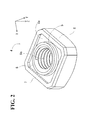
- FIG. 2 is a perspective view of an exemplary configuration of a self-piercing and clinch nut produced by the production apparatus according to the embodiment;
- FIG. 3 is a front view of the exemplary configuration of the self-piercing and clinch nut produced by the production apparatus according to the embodiment;
- FIG. 4 is a perspective view of another exemplary configuration of a self-piercing and clinch nut
- FIG. 5 is a front view of the another exemplary configuration of the self-piercing and clinch nut
- FIG. 6 is a plan view of an exemplary configuration of a forger according to the embodiment.
- FIG. 7 is a plan view of the exemplary configuration of the forger according to the embodiment.
- FIG. 8 is a plan view of an exemplary configuration of a first forging die assembly
- FIG. 9 is a front cross-sectional view of the exemplary configuration of the first forging die assembly.
- FIG. 10 is a front cross-sectional view of the exemplary configuration of the first forging die assembly
- FIG. 11 is a perspective view of an exemplary configuration of a first insert
- FIG. 12 is a plan view of the exemplary configuration of the first insert
- FIG. 13 is a front view of the exemplary configuration of the first insert
- FIG. 14 is a rear view of an exemplary configuration of a first punch
- FIG. 15 is a front cross-sectional view of an exemplary configuration of a second forging die assembly
- FIG. 16 is a plan view of an exemplary configuration of a second die
- FIG. 17 is a front cross-sectional view of the exemplary configuration of the second die
- FIG. 18 is a plan view of an exemplary configuration of a second insert
- FIG. 19 is a front view of the exemplary configuration of the second insert.
- FIG. 20 is a front cross-sectional view of an exemplary configuration of a third forging die assembly
- FIG. 21 is a plan view of an exemplary configuration of a third die
- FIG. 22 is a plan view of an exemplary configuration of a guide
- FIG. 23 is a front cross-sectional view of the exemplary configuration of the guide.
- FIG. 24 is a front view of an exemplary configuration of a third punch
- FIG. 25 is a rear view of an exemplary configuration of a fourth punch
- FIG. 26 is a front cross-sectional view illustrating a step of preliminarily forming a pilot portion and a surrounding wall of a blank
- FIG. 27 is a front cross-sectional view illustrating a step of inclining the surrounding wall of the blank toward the pilot portion.
- FIG. 28 is a front cross-sectional view illustrating a step of inclining the pilot portion of the blank toward the surrounding wall.
- FIG. 1 is a block diagram illustrating an exemplary configuration of an apparatus 1 to produce a self-piercing and clinch nut (hereinafter referred to simply as “production apparatus”) according to an embodiment.
- the production apparatus 1 mainly includes a feeder 3 , a forger 10 , and a controller 90 .
- FIG. 2 and the subsequent drawings are attached, as necessary, with an XYZ Cartesian coordinate system, in which the Z axis direction is assumed as the vertical direction and the XY plane is assumed as the horizontal plane.
- the feeder 3 feeds a material of blanks (nut blanks) to the forger 10 .
- the material of blanks is a wire material having an approximately rectangular cross-section.
- the forger 10 produces blanks for self-piercing and clinch nuts, and the blanks have an approximately rectangular external shape. A detailed configuration of the forger 10 will be described later.
- the controller 90 controls the feeder 3 and the forger 10 to operate.
- the controller 90 mainly includes a CPU 91 and a memory 92 .
- the CPU 91 executes, at a predetermined timing, operation control of the feeder 3 and the forger 10 , which are electrically connected to the controller 90 through a signal line 99 .
- FIGS. 2 and 3 are respectively a perspective view and a front view of an exemplary configuration of a self-piercing and clinch nut 4 produced by the production apparatus 1 according to this embodiment.
- FIGS. 4 and 5 are respectively a perspective view and a front view of an exemplary configuration of a self-piercing and clinch nut 104 , which is different from the self-piercing and clinch nut 4 .
- the self-piercing and clinch nut 4 is a nut to be secured on a parent material such as a steel sheet through application of pressure. As shown in FIGS. 2 and 3 , the self-piercing and clinch nut 4 mainly includes a pilot portion 6 , a surrounding wall (rib) 7 , a main body 8 , and a thick portion 9 .
- the main body 8 is an approximately rectangular parallelepiped having a through hole 9 a .
- the through hole 9 a extends in a direction indicated by the arrow AR1 (a direction in parallel to the arrow AR1 (which is along the Z axis) will be hereinafter occasionally referred to as “extending direction”).
- the through hole 9 a is a screw hole.
- the thick portion 9 is a truncated cone protruding from a central portion of a flat surface 8 a of the main body 8 . As shown in FIGS. 2 and 3 , the through hole 9 a is formed in the center of the thick portion 9 in a manner similar to the main body 8 .
- the pilot portion 6 is a tool to punch a hole in the parent material utilizing pressure exerted in the direction indicated by the arrow AR1. As shown in FIGS. 2 and 3 , the pilot portion 6 has a truncated-cone external shape protruding from the upper surface of the thick portion 9 in an outward direction from the main body 8 .
- the through hole 9 a is formed in the center of the pilot portion 6 in a manner similar to the main body 8 and the thick portion 9 .
- the surrounding wall 7 has a cylindrical shape along the outer periphery of the flat surface 8 a .
- the outer peripheral length and the inner peripheral length of the surrounding wall 7 in a direction perpendicular to the extending direction of the through hole 9 a decrease gradually as the distance from the flat surface 8 a increases.
- the thick portion 9 has an outer peripheral length in the direction perpendicular to the extending direction of the through hole 9 a .
- the outer peripheral length of the thick portion 9 decreases gradually as the distance from the flat surface 8 a increases.
- the pilot portion 6 has an outer peripheral length in the direction perpendicular to the extending direction of the through hole 9 a .
- the outer peripheral length of the pilot portion 6 increases gradually as the distance from the flat surface 8 a increases.
- the self-piercing and clinch nut 4 produced by the production apparatus 1 according to this embodiment will be compared with the self-piercing and clinch nut 104 , which has no thick portion 9 (see FIGS. 4 and 5 ).
- the comparison shows that a thickness TH1 of the thick portion 9 on the outer periphery of the through hole 9 a in the self-piercing and clinch nut 4 (see FIG. 3 ) can be set at a thickness larger than a thickness TH2 of a pilot portion 6 on the outer periphery of a through hole 9 a in the self-piercing and clinch nut 104 (see FIG. 5 ).
- the self-piercing and clinch nut 4 produced by the production apparatus 1 prevents the pilot portion 6 and the thick portion 9 from buckling, which may occur due to compressive stress of the pilot portion 6 and the thick portion 9 at the time of punching of the parent material.
- the self-piercing and clinch nut 4 produced by the production apparatus 1 ensures sufficient amount of the thickness TH1 of the thick portion 9 on the outer periphery of the through hole 9 a adjacent to the flat surface 8 a (see FIG. 3 ). This prevents the diameter of the through hole 9 a of the self-piercing and clinch nut 4 from changing (decreasing, for example) when the parent material is deformed to fill the gap between the pilot portion 6 and the surrounding wall 7 to clinch the parent material by the self-piercing and clinch nut 4 .
- the use of the self-piercing and clinch nut 4 produced by the production apparatus 1 according to this embodiment eliminates or minimizes such an occurrence that the self-piercing and clinch nut 4 cannot receive a screw after the self-piercing and clinch nut 4 has been secured on the parent material.
- FIGS. 6 and 7 are plan views illustrating an exemplary configuration of the forger 10 according to this embodiment.
- the forger 10 cuts the wire material fed from the feeder 3 into pieces of a desired size. Then, the forger 10 subjects the cut pieces of the wire material to a plurality of forging steps to produce blanks in forms before undergoing tapping (internal threading).
- the forger 10 mainly includes a preliminary forging die assembly 20 , a transfer mechanism 25 , a first forging die assembly 30 , a second forging die assembly 50 , and a third forging die assembly 70 .
- the preliminary forging die assembly 20 subjects the cut pieces of the wire material fed from the feeder 3 to desired preliminary forging. As shown in FIGS. 6 and 7 , the first forging die assembly 30 is disposed adjacent to the preliminary forging die assembly 20 . After the blanks have been processed in the preliminary forging die assembly 20 , the first forging die assembly 30 subjects each blank to processing for preliminary forming of the pilot portion 6 and the surrounding wall 7 (first processing).
- the second forging die assembly 50 is disposed adjacent to the first forging die assembly 30 . After the blanks have undergone the first processing in the first forging die assembly 30 , the second forging die assembly 50 subjects each blank to processing for inclining the pilot portion 6 toward the surrounding wall 7 (second processing).
- the third forging die assembly 70 is disposed adjacent to the second forging die assembly 50 . After the blanks have undergone the second processing in the second forging die assembly 50 , the third forging die assembly 70 subjects each blank to processing for inclining the surrounding wall 7 toward the pilot portion 6 and for forming the through hole 9 a in the pilot portion 6 (third processing).
- the transfer mechanism 25 includes a plurality of (three in this embodiment) grippers 26 ( 26 a to 26 c ).
- the transfer mechanism 25 transfers the blank between adjacent two forging die assemblies among the preliminary forging die assembly 20 , the first forging die assembly 30 , the second forging die assembly 50 , and the third forging die assembly 70 .
- the gripper 26 a of the transfer mechanism 25 transfers the blank between the preliminary forging die assembly 20 and the first forging die assembly 30 .
- the gripper 26 b of the transfer mechanism 25 transfers the blank between the first and second forging die assemblies 30 and 50 .
- the gripper 26 c of the transfer mechanism 25 transfers the blank between the second and third forging die assemblies 50 and 70 .
- FIG. 8 is a plan view of an exemplary configuration of the first forging die assembly 30 .
- FIGS. 9 and 10 are front cross-sectional views illustrating the exemplary configuration of the first forging die assembly 30 .
- FIGS. 11 to 13 are respectively a perspective view, a plan view, and a front view of an exemplary configuration of a first insert 33 .
- FIG. 14 is a rear view of an exemplary configuration of a first punch 40 .
- the first forging die assembly 30 mainly includes a first die 32 , the first insert 33 , a first pin 38 , and the first punch 40 . These elements 32 , 33 , 38 , 40 are accommodated in a die case 31 (see FIGS. 6 to 9 ).
- the first die 32 is a block to receive a blank. As shown in FIGS. 9 and 10 , the first die 32 has a first insert hole 32 a extending in one direction (Z axis direction). The first insert 33 has a cylindrical shape having a first platform 34 . When the blank is disposed in the first insert hole 32 a , the first insert 33 is fitted in the first insert hole 32 a with the first platform 34 opposed to the blank.
- the first insert 33 has a first hole 33 a .
- One of the two ends of the first hole 33 a on the first platform 34 side has a first opening 33 b .
- a portion of the first insert 33 adjacent to the first opening 33 b is chamfered flatly to form a first chamfer 33 c .
- the inner peripheral length of the first chamfer 33 c (more specifically, the inner peripheral length of the first chamfer 33 c in a direction perpendicular to the extending direction of the first hole 33 a ) increases gradually as the distance to the first opening 33 b decreases.
- a first processing space 35 in which the blank is processed is defined in the first insert hole 32 a .
- a first surrounding groove 36 is defined by a first inner peripheral wall 32 b (see FIGS. 9 and 10 ), which defines the first insert hole 32 a , and a first side wall 34 a (see FIGS. 12 and 13 ) of the first platform 34 .
- the first punch 40 is disposed above the first insert 33 and the first pin 38 , and is movable to and away from the first processing space 35 . As shown in FIG. 14 , the first punch 40 mainly includes a shank 41 and a distal end 42 .
- the shank 41 is a rod-shaped member extending in the Z axis direction.
- the shank 41 has an approximately rectangular cross-section in a direction perpendicular to the axial direction.
- the distal end 42 is a protrusion from an end portion 41 a of the shank 41 .
- the distal end 42 presses an upper portion of the blank adjacent to its axis to effect preliminary forming of the through hole 9 a of the self-piercing and clinch nut 4 .
- the first pin 38 is a rod-shaped member fitted in the first hole 33 a of the first insert 33 , and is movable to and away from the first processing space 35 . This ensures that when the first pin 38 moves upward, the blank is discharged from the first processing space 35 . Adjacent to a first end portion 38 a of the first pin 38 , the cross-sectional area of the first pin 38 in the direction perpendicular to the axial direction decreases gradually as the distance to the first punch 40 decreases.
- FIG. 15 is a front cross-sectional view of an exemplary configuration of the second forging die assembly 50 .
- FIGS. 16 and 17 are respectively a plan view and a front cross-sectional view of an exemplary configuration of a second die 52 .
- FIGS. 18 and 19 are respectively a plan view and a front view of an exemplary configuration of a second insert 53 .
- the second forging die assembly 50 mainly includes the second die 52 , the second insert 53 , a second pin 58 , and a second punch 60 . These elements 52 , 53 , 58 , 60 are accommodated in a die case 51 (see FIGS. 6 and 7 ).
- the second die 52 is a block to receive the blank.
- the second die 52 has a second insert hole 52 a extending in one direction (Z axis direction).
- the second insert 53 is a cylindrical member having a second platform 54 .
- the second insert 53 has a second hole 53 a .
- One of the two ends of the second hole 53 a on the second platform 54 side has a second opening 53 b .
- a portion of the second insert 53 adjacent to the second opening 53 b is chamfered flatly to form a second chamfer 53 c .
- the inner peripheral length of the second chamfer 53 c (more specifically, the inner peripheral length of the second chamfer 53 c in a direction perpendicular to an extending direction of the second hole 53 a ) increases gradually as the distance to the second opening 53 b decreases.
- a second processing space 55 in which the blank is processed is defined in the second insert hole 52 a .
- a second surrounding groove 56 (see FIG. 15 ) is defined by a second inner peripheral wall 52 b (see FIG. 15 ), which defines the second insert hole 52 a , and a second side wall 54 a (see FIGS. 18 and 19 ) of the second platform 54 .
- a second punch 60 is disposed above the second insert 53 and the second pin 58 , and is movable to and away from the second processing space 55 . As shown in FIG. 14 , the second punch 60 has a hardware configuration similar to the first punch 40 of the first forging die assembly 30 .
- the second pin 58 is a rod-shaped member having a hardware configuration similar to the first pin 38 of the first forging die assembly 30 . As shown in FIG. 15 , the second pin 58 is fitted in the second hole 53 a of the second insert 53 , and is movable to and away from the second processing space 55 . Thus, when the second pin 58 moves upward, the blank is discharged from the second processing space 55 .
- FIG. 20 is a front cross-sectional view of an exemplary configuration of the third forging die assembly 70 .
- FIG. 21 is a plan view of an exemplary configuration of a third die 72 .
- FIGS. 22 and 23 are respectively a plan view and a front cross-sectional view of an exemplary configuration of a guide 73 .
- FIG. 24 is a front view of an exemplary configuration of a third punch 80 .
- FIG. 25 is a rear view of an exemplary configuration of a fourth punch 85 .
- the third forging die assembly 70 mainly includes the third die 72 , the guide 73 , the third punch 80 , and the fourth punch 85 . These elements 72 , 73 , 80 , 85 are accommodated in a die case 71 (see FIGS. 6 and 7 ).
- the third die 72 is a block to receive the blank. As shown in FIGS. 20 and 21 , the third die 72 has a third insert hole 72 a extending in one direction (Z axis direction). As shown in FIG. 21 , the third insert hole 72 a has a plurality of (four in this embodiment) notches 72 c along a third inner peripheral wall 72 b.
- the guide 73 is a cylindrical member having a third hole 73 a . As shown in FIGS. 22 and 23 , the guide 73 includes an annular protrusion 74 along an opening 73 b of the third hole 73 a . As shown in FIG. 23 , the annular protrusion 74 is formed on an opposed surface 73 d opposed to the blank.
- a plurality of (four in this embodiment) guide holes 73 c extend in one direction (Z axis direction).
- the guide holes 73 c are fitted with corresponding, respective third pins 88 .
- a third processing space 75 is defined in the third insert hole 72 a (see FIG. 20 ).
- the third punch 80 is a punching member fitted in the third insert hole 72 a .
- the third punch 80 mainly includes a rod-shaped shank 81 , a distal end 82 , and an inclined portion 83 .
- the shank 81 and the distal end 82 are rod-shaped members, and the distal end 82 is disposed closer to the blank than the shank 81 is to the blank.
- the inclined portion 83 has a frustum shape, and is disposed between the shank 81 and the distal end 82 . As shown in FIG. 24 , the outer diameter of the inclined portion 83 gradually increases from a first connection position CP1 to a second connection position CP2.
- the fourth punch 85 is a cylindrical punching member disposed above the guide 73 , the third punch 80 , and the plurality of third pins 88 .
- the fourth punch 85 is movable to and away from the third processing space 75 .
- the through hole 9 a is formed in the blank.
- the plurality of (four in this embodiment) third pins 88 are knockout pins to discharge the blank from the third processing space 75 . As shown in FIGS. 20 to 23 , the plurality of third pins 88 are movable to and away from the third processing space 75 , and are disposed along the third inner peripheral wall 72 b , which defines the third insert hole 72 a.
- the blank is reliably discharged from the third processing space 75 . This eliminates or minimizes the production apparatus 1 stopping its operation due to discharge failure of the blank.
- FIGS. 26 to 28 are front cross-sectional views respectively illustrating the first processing in the first forging die assembly 30 , the second processing in the second forging die assembly 50 , and the third processing in the third forging die assembly 70 . Referring to FIGS. 26 to 28 , forging of a blank performed by the production apparatus 1 will be described.
- a blank 5 disposed in the first processing space 35 is clamped between the first insert 33 and the first pin 38 , and the first punch 40 , as shown in FIG. 26 .
- the preliminary form of the pilot portion 6 is pressed by the first chamfer 33 c of the first insert 33 .
- the surrounding wall 7 is preliminarily formed around the pilot portion 6 .
- the distal end 42 of the first punch 40 presses an upper portion of the blank 5 to form a provisional dent 9 b , which is a preliminary form of the penetrating hole.
- the blank done with the first processing is discharged from the first processing space 35 .
- the blank 5 is transferred from the first forging die assembly 30 to the second forging die assembly 50 using the gripper 26 b of the transfer mechanism 25 .
- the blank 5 is now transferred from the first processing space 35 and disposed in the second processing space 55 .
- the blank 5 is clamped between the second insert 53 and the second pin 58 , and the second punch 60 , as shown in FIG. 27 .
- the inner peripheral length of the second inner peripheral wall 52 b in the second surrounding groove 56 decreases gradually as the distance from the second punch 60 increases.
- the surrounding wall 7 of the blank 5 inserted in the second surrounding groove 56 is inclined toward the pilot portion 6 .
- the preliminary form of pilot portion 6 which has been formed in the first processing, is widened in a horizontal direction (X axis direction).
- the preliminary form of the pilot portion 6 is pressed by the second chamfer 53 c of the second insert 53 .
- the distal end 62 of the second punch 60 presses an upper portion of the blank 5 in a manner similar to the first processing.
- the blank 5 done with the second processing is discharged from the second processing space 55 .
- the blank 5 is transferred from the second forging die assembly 50 to the third forging die assembly 70 using the gripper 26 c of the transfer mechanism 25 .
- the blank 5 is now transferred from the second processing space 55 and disposed in the third processing space 75 .
- the blank 5 is clamped between the guide 73 and the third punch 80 , and the fourth punch 85 , as shown in FIG. 28 .
- a portion of the blank 5 adjacent to its axis is moved upward and clamped between the distal end 82 of the third punch 80 and the fourth punch 85 .
- the provisional dent 9 b (see FIGS. 26 and 27 ), which has been formed in the first processing and the second processing, is penetrated to result in the through hole 9 a along the direction (Z axis direction) in which the distal end 82 proceeds.
- the outer diameter of the shank 81 is set at a first outer diameter ED1, which is approximately equal to an inner diameter ID of the third hole 73 a .
- the outer diameter of the distal end 82 is set at a second outer diameter ED2, which is smaller than the first outer diameter ED1.
- a third outer diameter ED3 of the inclined portion 83 is defined at the first connection position CP1 by the distal end 82 .
- the third outer diameter ED3 is approximately equal to the second outer diameter ED2.
- a fourth outer diameter ED4 of the inclined portion 83 is defined at the second connection position CP2 by the shank 81 .
- the fourth outer diameter ED4 is approximately equal to the first outer diameter ED1.
- the pilot portion 6 is precisely processed mainly by punching and pressing from the inclined portion 83 and the shank 81 , and inclined toward the surrounding wall 7 .
- the third punch 80 is moved away from the third processing space 75 and the plurality of third pins 88 are moved upward, the blank 5 done with the third processing is discharged from the third processing space 75 .
- the blank 5 discharged from the third processing space 75 is transferred from the third forging die assembly 70 to a device in charge of a subsequent process by a transfer mechanism, not shown.
- the height of the annular protrusion 74 from the opposed surface 73 d is set at a height SH1 (see FIG. 23 ), which is larger than at least the height of the surrounding wall 7 of the blank 5 (that is, the height of the surrounding wall 7 from the flat surface 8 a surrounded by the pilot portion 6 and the surrounding wall 7 ; see FIG. 3 ).
- the production apparatus 1 performs the following processing steps:
- the pilot portion 6 and the surrounding wall 7 are preliminarily formed on the blank 5 (see FIG. 26 );
- the surrounding wall 7 of the blank 5 is inclined toward the pilot portion 6 (see FIG. 27 );
- the through hole 9 a is formed in the pilot portion 6 , and at the same time, the pilot portion 6 is inclined toward the surrounding wall 7 .
- punching is performed in the final step. This ensures that even if the blank 5 that has not reached the final step is erroneously discharged to the subsequent process, the defective blank is caught by error management included tapping processing in the subsequent process. That is, a blank 5 without through hole 9 a cannot undergo tapping in the first place.
- the production apparatus 1 performs punching in the final step. This reliably eliminates production of a self-piercing and clinch nut 4 that has not been subjected to the first processing and/or the second processing.
- the first hole 33 a is formed in the first insert 33 .
- the portion of the first insert 33 adjacent to the first opening 33 b of the first hole 33 a on the first platform 34 side is chamfered flatly to form the first chamfer 33 c .
- the second hole 53 a is formed in the second insert 53 .
- the portion of the second insert 53 adjacent to the second opening 53 b of the second hole 53 a on the second platform 54 side is chamfered flatly to form the second chamfer 53 c in the manner similar to the case of the first opening 33 b.
- the preliminary form of the pilot portion 6 of the blank 5 is pressed by the first chamfer 33 c of the first insert 33 and the second chamfer 53 c of the second insert 53 , and inclined toward the surrounding wall 7 .
- the use of the self-piercing and clinch nut 4 produced by the production apparatus 1 according to this embodiment ensures that the pilot portion 6 and the thick portion 9 are prevented from buckling due to compressive stress in the pilot portion 6 and the thick portion 9 at the time of punching of the parent material.
- the use of the self-piercing and clinch nut 4 produced by the production apparatus 1 according to this embodiment ensures that when the parent material is deformed to fill the gap between the pilot portion 6 and the surrounding wall 7 to clinch the parent material by the self-piercing and clinch nut 4 , the diameter of the through hole 9 a of the self-piercing and clinch nut 4 is prevented from changing. This eliminates or minimizes such an occurrence that the self-piercing and clinch nut 4 cannot receive a screw after the self-piercing and clinch nut 4 has been secured on the parent material.
- the feeder 3 feeds to the forger 10 a wire material having an approximately rectangular cross-section as a material of the blank 5 .
- first chamfer 33 c of the first insert 33 and the second chamfer 53 c of the second insert 53 are flat. This, however, should not be construed in a limiting sense. Another possible example is that the first and second chamfers 33 c and 53 c are curved surfaces having predetermined curvatures.
- the inclination of the first chamfer 33 c and the inclination of the second chamfer 53 c are approximately uniform. This, however, should not be construed in a limiting sense. The inclination of the first chamfer 33 c and the inclination of the second chamfer 53 c may vary.
- the first punch 40 includes the shank 41 and the distal end 42 integral with each other. This, however, should not be construed in a limiting sense. Another example is that a rod-shaped pin is fitted in a cylindrical punch to constitute the first punch 40 . That is, different elements may be combined to constitute the first punch 40 . Similarly, different elements may be combined to constitute the second punch 60 .
- the blank 5 is clamped between the second insert 53 and the second pin 58 , and the second punch 60 .
- This should not be construed in a limiting sense.
- the second pin 58 is moved downward to a withdrawal position (position indicated by the chain double-dashed line in FIG. 27 ).
- the blank 5 is clamped between the second insert 53 and the second punch 60 .
- the first punch 40 is movable to and away from the first processing space 35 .
- the first die 32 and the first insert 33 may be movable to and away from the first punch 40 , or all of the first die 32 , the first insert 33 , and the first punch 40 may be movable to and away from each other. It may suffice that the first punch 40 is movable to and away from the first processing space 35 .
- first pin 38 is movable to and away from the first processing space 35
- second pin 58 and the second punch 60 are movable to and away from the second processing space 55
- fourth punch 85 and the plurality of the third pins 88 are movable to and away from the third processing space 75 .
- the number of the plurality of third pins 88 is four. This, however, should not be construed as limiting the number of the third pins 88 . Insofar as the blank 5 is reliably discharged from the third processing space 75 , the number of the third pins 88 may be three, or five or more.
- the third die 72 and the guide 73 are different elements. This, however, should not be construed in a limiting sense. These elements 72 and 73 may be integral with each other.
- an apparatus to produce a self-piercing and clinch nut includes a first forging die assembly, a second forging die assembly, a third forging die assembly, a transfer mechanism, and a controller.
- the first forging die assembly is configured to subject a blank to first processing.
- the first forging die assembly includes a first die, a first cylindrical insert, a first punch, and a first pin.
- the first die includes a first insert hole and a first inner peripheral wall defining the first insert hole.
- the first cylindrical insert includes a first platform. The first cylindrical insert is fitted in the first insert hole with the first platform opposed to the blank so as to define a first processing space in which the blank is to be processed.
- the first platform includes a first side wall.
- the first side wall and the first inner peripheral wall define a first surrounding groove.
- the first punch is movable to and away from the first processing space.
- the first pin is fitted in a first hole of the first insert.
- the second forging die assembly is adjacent to the first forging die assembly and is configured to subject the blank to second processing after the blank has undergone the first processing in the first forging die assembly.
- the second forging die assembly includes a second die, a second cylindrical insert, and a second punch.
- the second die includes a second insert hole and a second inner peripheral wall defining the second insert hole.
- the second cylindrical insert includes a second platform.
- the second cylindrical insert is fitted in the second insert hole with the second platform opposed to the blank so as to define a second processing space in which the blank is to be processed.
- the second platform includes a second side wall.
- the second side wall and the second inner peripheral wall define a second surrounding groove.
- the second punch is movable to and away from the second processing space.
- An inner peripheral length of the second inner peripheral wall in the second surrounding groove decreases as a distance from the second punch increases.
- the third forging die assembly is adjacent to the second forging die assembly and is configured to subject the blank to third processing after the blank has undergone the second processing in the second forging die assembly.
- the third forging die assembly includes a third die, a cylindrical guide, and a third punch.
- the third die includes a third insert hole.
- the cylindrical guide includes a third hole.
- the cylindrical guide includes an annular protrusion along an opening of the third hole.
- the annular protrusion is inserted in the third insert hole to define a third processing space.
- the annular protrusion is formed on an opposed surface opposed to the blank.
- a height of the annular protrusion from the opposed surface is larger than at least a height of a surrounding wall of the blank.
- the third punch is fitted in the third hole.
- the third punch includes a rod-shaped shank, a rod-shaped distal end, and an inclined frustum portion.
- the rod-shaped distal end is closer to the blank than the shank is to the blank.
- the inclined frustum portion is between the shank and the distal end.
- the fourth cylindrical punch is movable to and away from the third processing space.
- the fourth cylindrical punch is configured to clamp the blank between the third punch and the fourth cylindrical punch so as to define a through hole in the blank.
- the transfer mechanism is configured to transfer the blank between adjacent two forging die assemblies among the first forging die assembly, the second forging die assembly, and the third forging die assembly.
- the controller is configured to control the first forging die assembly, the second forging die assembly, the third forging die assembly, and the transfer mechanism to operate.
- the controller is configured to clamp the blank in the first processing space between the first pin and the first insert, and the first punch so as to press the blank forced in the first hole of the first insert using a first end portion of the first pin to form a pilot portion on the blank, and so as to form the blank forced in the first surrounding groove into the surrounding wall surrounding the pilot portion.
- the controller is configured to clamp the blank in the second processing space between the second insert and the second punch so as to incline the surrounding wall inserted in the second surrounding groove toward the pilot portion.
- the controller is configured to clamp the blank in the third processing space between the guide and the third punch, and the fourth punch so as to form the through hole in the blank and incline the pilot portion toward the surrounding wall.
- an apparatus to produce a self-piercing and clinch nut includes a first forging die assembly, a second forging die assembly, a third forging die assembly, and a transfer mechanism.
- the first forging die assembly is configured to subject a blank to first processing.
- the first forging die assembly includes a first die, a first cylindrical insert, a first punch, and a first pin.
- the first die includes a first insert hole and a first inner peripheral wall defining the first insert hole.
- the first cylindrical insert includes a first platform. The first cylindrical insert is fitted in the first insert hole with the first platform opposed to the blank so as to define a first processing space in which the blank is to be processed.
- the first platform includes a first side wall.
- the first side wall and the first inner peripheral wall define a first surrounding groove.
- the first punch is movable to and away from the first processing space.
- the first pin is fitted in a first hole of the first insert.
- the second forging die assembly is adjacent to the first forging die assembly and is configured to subject the blank to second processing after the blank has undergone the first processing in the first forging die assembly.
- the second forging die assembly includes a second die, a second cylindrical insert, and a second punch.
- the second die includes a second insert hole and a second inner peripheral wall defining the second insert hole.
- the second cylindrical insert includes a second platform.
- the second cylindrical insert is fitted in the second insert hole with the second platform opposed to the blank so as to define a second processing space in which the blank is to be processed.
- the second platform includes a second side wall.
- the second side wall and the second inner peripheral wall define a second surrounding groove.
- the second punch is movable to and away from the second processing space.
- An inner peripheral length of the second inner peripheral wall in the second surrounding groove decreases as a distance from the second punch increases.
- the third forging die assembly is adjacent to the second forging die assembly and is configured to subject the blank to third processing after the blank has undergone the second processing in the second forging die assembly.
- the third forging die assembly includes a third die, a cylindrical guide, and a third punch.
- the third die includes a third insert hole.
- the cylindrical guide includes a third hole.
- the cylindrical guide includes an annular protrusion along an opening of the third hole.
- the annular protrusion is inserted in the third insert hole to define a third processing space.
- the annular protrusion is formed on an opposed surface opposed to the blank.
- a height of the annular protrusion from the opposed surface is larger than at least a height of a surrounding wall of the blank.
- the third punch is fitted in the third hole.
- the third punch includes a rod-shaped shank, a rod-shaped distal end, and an inclined frustum portion.
- the rod-shaped distal end is closer to the blank than the shank is to the blank.
- the inclined frustum portion is between the shank and the distal end.
- the fourth cylindrical punch is movable to and away from the third processing space.
- the fourth cylindrical punch is configured to clamp the blank between the third punch and the fourth cylindrical punch so as to define a through hole in the blank.
- the transfer mechanism is configured to transfer the blank between adjacent two forging die assemblies among the first forging die assembly, the second forging die assembly, and the third forging die assembly.
- a method is for producing a self-piercing and clinch nut using a first forging die assembly, a second forging die assembly, and a third forging die assembly.
- the first forging die assembly includes a first die, a first cylindrical insert, a first punch, and a first pin.
- the first die includes a first insert hole and a first inner peripheral wall defining the first insert hole.
- the first cylindrical insert includes a first platform. The first cylindrical insert is fitted in the first insert hole with the first platform opposed to a blank so as to define a first processing space in which the blank is to be processed.
- the first platform includes a first side wall. The first side wall and the first inner peripheral wall define a first surrounding groove.
- the first punch is movable to and away from the first processing space.
- the first pin is fitted in a first hole of the first insert.
- the second forging die assembly is adjacent to the first forging die assembly and is configured to subject the blank to second processing after the blank has undergone the first processing in the first forging die assembly.
- the second forging die assembly includes a second die, a second cylindrical insert, and a second punch.
- the second die includes a second insert hole and a second inner peripheral wall defining the second insert hole.
- the second cylindrical insert includes a second platform.
- the second cylindrical insert is fitted in the second insert hole with the second platform opposed to the blank so as to define a second processing space in which the blank is to be processed.
- the second platform includes a second side wall.
- the second side wall and the second inner peripheral wall define a second surrounding groove.
- the second punch is movable to and away from the second processing space.
- An inner peripheral length of the second inner peripheral wall in the second surrounding groove decreases as a distance from the second punch increases.
- the third forging die assembly is adjacent to the second forging die assembly and is configured to subject the blank to third processing after the blank has undergone the second processing in the second forging die assembly.
- the third forging die assembly includes a third die, a cylindrical guide, and a third punch.
- the third die includes a third insert hole.
- the cylindrical guide includes a third hole.
- the cylindrical guide includes an annular protrusion along an opening of the third hole. The annular protrusion is inserted in the third insert hole to define a third processing space.
- the annular protrusion is formed on an opposed surface opposed to the blank.
- a height of the annular protrusion from the opposed surface is larger than at least a height of a surrounding wall of the blank.
- the third punch is fitted in the third hole.
- the third punch includes a rod-shaped shank, a rod-shaped distal end, and an inclined frustum portion.
- the rod-shaped distal end is closer to the blank than the shank is to the blank.
- the inclined frustum portion is between the shank and the distal end.
- the fourth cylindrical punch is movable to and away from the third processing space.
- the fourth cylindrical punch is configured to clamp the blank between the third punch and the fourth cylindrical punch so as to define a through hole in the blank.
- the method includes providing the blank in the first processing space.
- the blank After the blank has been provided in the first processing space, the blank is clamped between the first pin and the first insert, and the first punch so as to press the blank forced in the first hole of the first insert using a first end portion of the first pin to form a pilot portion on the blank and to form the blank forced in the first surrounding groove into a surrounding wall surrounding the pilot portion.
- the blank After the blank has been clamped between the first pin and the first insert, and the first punch, the blank is provided in the second processing space. After the blank has been provided in the second processing space, the blank is clamped between the second insert and the second punch so as to incline the surrounding wall inserted in the second surrounding groove toward the pilot portion. After the blank has been clamped between the second insert and the second punch, the blank is provided in the third processing space. After the blank has been provided in the third processing space, the blank is clamped between the guide and the third punch, and the fourth punch so as to form the through hole and to incline the pilot portion toward the surrounding wall.
Landscapes
- Engineering & Computer Science (AREA)
- Mechanical Engineering (AREA)
- Forging (AREA)
Abstract
Description
Claims (12)
Applications Claiming Priority (2)
| Application Number | Priority Date | Filing Date | Title |
|---|---|---|---|
| JP2014-135592 | 2014-07-01 | ||
| JP2014135592A JP5686490B1 (en) | 2014-07-01 | 2014-07-01 | Piercing nut manufacturing apparatus and piercing nut manufacturing method |
Publications (1)
| Publication Number | Publication Date |
|---|---|
| US8899089B1 true US8899089B1 (en) | 2014-12-02 |
Family
ID=51948250
Family Applications (1)
| Application Number | Title | Priority Date | Filing Date |
|---|---|---|---|
| US14/447,572 Active US8899089B1 (en) | 2014-07-01 | 2014-07-30 | Apparatus to produce self-piercing and clinch nut and method for producing self-piercing and clinch nut |
Country Status (5)
| Country | Link |
|---|---|
| US (1) | US8899089B1 (en) |
| EP (1) | EP2962782B1 (en) |
| JP (1) | JP5686490B1 (en) |
| CN (1) | CN105312482B (en) |
| BR (1) | BR102015003610A2 (en) |
Cited By (3)
| Publication number | Priority date | Publication date | Assignee | Title |
|---|---|---|---|---|
| US20150026950A1 (en) * | 2010-12-03 | 2015-01-29 | BTM Corportion | Method of using a pierce nut insertion tool |
| EP3081320A1 (en) * | 2015-04-14 | 2016-10-19 | Shinjo Holdings Co., Ltd. | Apparatus to produce self-piercing and clinch nut and method for producing self-piercing and clinch nut |
| US10161435B2 (en) * | 2016-02-15 | 2018-12-25 | Whitesell Formed Components, Inc. | Self-attaching fastener and panel assembly, and method of attaching |
Families Citing this family (6)
| Publication number | Priority date | Publication date | Assignee | Title |
|---|---|---|---|---|
| JP5818232B1 (en) * | 2015-04-14 | 2015-11-18 | 有限会社新城製作所 | Piercing nut manufacturing apparatus and piercing nut manufacturing method |
| JP5822043B1 (en) * | 2015-04-14 | 2015-11-24 | 有限会社新城製作所 | Piercing nut manufacturing apparatus and piercing nut manufacturing method |
| CN106271517B (en) * | 2016-09-28 | 2018-08-28 | 泉州鹏宜机械有限公司 | A kind of assemble method and assembling equipment of nut |
| CN109967687B (en) * | 2019-03-28 | 2022-12-06 | 常州市爱伦机械有限公司 | Gear forging waste recycling reprocessing device |
| CN112008032B (en) * | 2019-05-31 | 2022-05-20 | 宾科精密部件(中国)有限公司 | Extrusion forming method and forming device for self-fastening I-shaped rivet |
| CN110883173A (en) * | 2019-12-25 | 2020-03-17 | 浙江鼎盛汽车紧固件有限公司 | Tire nut stamping method, forming die and assembly device |
Citations (5)
| Publication number | Priority date | Publication date | Assignee | Title |
|---|---|---|---|---|
| US5340251A (en) * | 1992-01-31 | 1994-08-23 | Multifastener Corporation | Self-attaching fastener and installation die |
| JPH0829392B2 (en) | 1993-12-17 | 1996-03-27 | 有限会社新城製作所 | Pierce nut manufacturing equipment |
| US7131311B1 (en) * | 2005-11-10 | 2006-11-07 | Honda Motor Co. Ltd. | Method of and apparatus for forming forging blank |
| US7314417B2 (en) * | 2000-03-31 | 2008-01-01 | Profil Verbindungstechnik Gmbh & Co. Kg | Method for the manufacture of hollow body elements, hollow body element and also progressive tool for carrying out the method |
| US20120316001A1 (en) * | 2011-06-07 | 2012-12-13 | Pias Sales Co., Ltd. | Pierce nut manufacturing apparatus |
Family Cites Families (7)
| Publication number | Priority date | Publication date | Assignee | Title |
|---|---|---|---|---|
| GB991487A (en) * | 1961-10-10 | 1965-05-12 | Multifastener Corp | Nut and panel assembly and method of making same |
| US3793658A (en) * | 1971-06-03 | 1974-02-26 | Multifastener Corp | Method of forming a fastener |
| RU2056212C1 (en) * | 1993-08-23 | 1996-03-20 | Акционерное общество "Автонормаль" | Method of making polyhedral nuts with convex-concave lateral surface and with flange |
| JP2001300683A (en) * | 2000-04-18 | 2001-10-30 | Honda Motor Co Ltd | Piercing nut manufacturing method |
| JP3933605B2 (en) * | 2003-05-12 | 2007-06-20 | 有限会社新城製作所 | Piercing nut manufacturing method |
| EP1559488B1 (en) * | 2004-01-29 | 2017-04-26 | PROFIL-Verbindungstechnik GmbH & Co. KG | Method for the manufacture of hollow elements and progressive die for carrying out the method. |
| CN101934337B (en) * | 2010-09-21 | 2012-11-21 | 上海交通大学 | Ring-shaped electro-plastic self-piercing riveting system |
-
2014
- 2014-07-01 JP JP2014135592A patent/JP5686490B1/en active Active
- 2014-07-30 US US14/447,572 patent/US8899089B1/en active Active
- 2014-12-15 EP EP14198028.4A patent/EP2962782B1/en active Active
-
2015
- 2015-02-15 CN CN201510081962.9A patent/CN105312482B/en active Active
- 2015-02-20 BR BR102015003610A patent/BR102015003610A2/en active Search and Examination
Patent Citations (7)
| Publication number | Priority date | Publication date | Assignee | Title |
|---|---|---|---|---|
| US5340251A (en) * | 1992-01-31 | 1994-08-23 | Multifastener Corporation | Self-attaching fastener and installation die |
| JPH0829392B2 (en) | 1993-12-17 | 1996-03-27 | 有限会社新城製作所 | Pierce nut manufacturing equipment |
| US5618237A (en) * | 1993-12-17 | 1997-04-08 | Yugenkaisha Shinjo Seisakusho | Apparatus for making self-piercing nuts |
| US7314417B2 (en) * | 2000-03-31 | 2008-01-01 | Profil Verbindungstechnik Gmbh & Co. Kg | Method for the manufacture of hollow body elements, hollow body element and also progressive tool for carrying out the method |
| US7131311B1 (en) * | 2005-11-10 | 2006-11-07 | Honda Motor Co. Ltd. | Method of and apparatus for forming forging blank |
| US20120316001A1 (en) * | 2011-06-07 | 2012-12-13 | Pias Sales Co., Ltd. | Pierce nut manufacturing apparatus |
| JP5325934B2 (en) | 2011-06-07 | 2013-10-23 | ピアス販売株式会社 | Piercing nut manufacturing equipment |
Cited By (7)
| Publication number | Priority date | Publication date | Assignee | Title |
|---|---|---|---|---|
| US20150026950A1 (en) * | 2010-12-03 | 2015-01-29 | BTM Corportion | Method of using a pierce nut insertion tool |
| US9931720B2 (en) * | 2010-12-03 | 2018-04-03 | Btm Company Llc | Method of using a pierce nut insertion tool |
| EP3081320A1 (en) * | 2015-04-14 | 2016-10-19 | Shinjo Holdings Co., Ltd. | Apparatus to produce self-piercing and clinch nut and method for producing self-piercing and clinch nut |
| CN106040956A (en) * | 2015-04-14 | 2016-10-26 | 有限会社新城控股 | Apparatus to produce self-piercing and clinch nut and method of producing self-piercing and clinch nut |
| CN106040956B (en) * | 2015-04-14 | 2018-03-30 | 有限会社新城控股 | Rush from the manufacture device for rushing nut and certainly the manufacture method of nut |
| US10010929B2 (en) | 2015-04-14 | 2018-07-03 | Shinjo Holdings Co., Ltd. | Apparatus to produce self-piercing and clinch nut and method of producing self-piercing and clinch nut |
| US10161435B2 (en) * | 2016-02-15 | 2018-12-25 | Whitesell Formed Components, Inc. | Self-attaching fastener and panel assembly, and method of attaching |
Also Published As
| Publication number | Publication date |
|---|---|
| JP2016013560A (en) | 2016-01-28 |
| EP2962782A1 (en) | 2016-01-06 |
| JP5686490B1 (en) | 2015-03-18 |
| CN105312482B (en) | 2018-07-03 |
| EP2962782B1 (en) | 2017-08-23 |
| CN105312482A (en) | 2016-02-10 |
| BR102015003610A2 (en) | 2017-05-30 |
Similar Documents
| Publication | Publication Date | Title |
|---|---|---|
| EP2962782B1 (en) | Apparatus to produce self-piercing and clinch nut and method for producing self-piercing and clinch nut | |
| JP5300027B2 (en) | Fixing method of pierce nut | |
| US11224909B2 (en) | Protrusion molding device, protrusion molding method, and molded article | |
| CN101808761B (en) | For manufacturing method and apparatus and the lock washer of lock washer | |
| EP2025430B1 (en) | Clutch gear manufacturing apparatus and clutch gear manufacturing method | |
| EP3320997A1 (en) | Protrusion molding device, protrusion molding method, and molded article | |
| US11471930B2 (en) | Molding die structure for forming oblique teeth on a rivet nut | |
| SE0802421A1 (en) | Method and apparatus for pressing a collar in a metal plate, as well as collar and sheet metal plate | |
| CN1246107C (en) | Manufacturing method and device for thin hexagonal socket head screw with wrench guide hole | |
| WO2016013405A1 (en) | Method for manufacturing oval swaged collar | |
| JP2020022983A (en) | Punch processing device and punch processing method | |
| US20140298878A1 (en) | Method and system for metal drawing and redrawing | |
| US10010929B2 (en) | Apparatus to produce self-piercing and clinch nut and method of producing self-piercing and clinch nut | |
| US20230147754A1 (en) | Metalworking apparatus and metalworking method | |
| US20140196518A1 (en) | Cut-off end surface improvement | |
| JP2011098357A (en) | Method for manufacturing insert fitting, and insert fitting manufactured by the same | |
| JP2002224789A (en) | Manufacturing method of crude material for wedge bolt | |
| US11565302B2 (en) | Press working apparatus, and setting method and maintenance method thereof | |
| US10478886B2 (en) | Stamping method and stamping apparatus | |
| CN114054659B (en) | Diagonal pattern forming die structure for riveting nuts | |
| US8016533B2 (en) | Lock nut with low on/high off torque control | |
| KR20170072500A (en) | Tapping plate and the method thereof | |
| US2408793A (en) | Manufacture of nuts and the like | |
| KR20170032983A (en) | Method for manufacturing ball joint | |
| KR100811299B1 (en) | Ball stud manufacturing method and apparatus |
Legal Events
| Date | Code | Title | Description |
|---|---|---|---|
| AS | Assignment |
Owner name: SHINJO MANUFACTURING CO., LTD., JAPAN Free format text: ASSIGNMENT OF ASSIGNORS INTEREST;ASSIGNOR:SHINJO, TADASHI;REEL/FRAME:033427/0422 Effective date: 20140730 |
|
| STCF | Information on status: patent grant |
Free format text: PATENTED CASE |
|
| AS | Assignment |
Owner name: SHINJO HOLDINGS CO., LTD., JAPAN Free format text: CHANGE OF NAME;ASSIGNOR:SHINJO MANUFACTURING CO., LTD.;REEL/FRAME:039492/0659 Effective date: 20160104 |
|
| MAFP | Maintenance fee payment |
Free format text: PAYMENT OF MAINTENANCE FEE, 4TH YEAR, LARGE ENTITY (ORIGINAL EVENT CODE: M1551) Year of fee payment: 4 |
|
| MAFP | Maintenance fee payment |
Free format text: PAYMENT OF MAINTENANCE FEE, 8TH YEAR, LARGE ENTITY (ORIGINAL EVENT CODE: M1552); ENTITY STATUS OF PATENT OWNER: LARGE ENTITY Year of fee payment: 8 |
|
| MAFP | Maintenance fee payment |
Free format text: PAYMENT OF MAINTENANCE FEE, 12TH YEAR, LARGE ENTITY (ORIGINAL EVENT CODE: M1553); ENTITY STATUS OF PATENT OWNER: LARGE ENTITY Year of fee payment: 12 |