US8898856B2 - Dirt cup with secondary cyclonic cleaning chambers - Google Patents
Dirt cup with secondary cyclonic cleaning chambers Download PDFInfo
- Publication number
- US8898856B2 US8898856B2 US13/381,279 US201113381279A US8898856B2 US 8898856 B2 US8898856 B2 US 8898856B2 US 201113381279 A US201113381279 A US 201113381279A US 8898856 B2 US8898856 B2 US 8898856B2
- Authority
- US
- United States
- Prior art keywords
- ribbing
- vacuum cleaner
- sidewall
- bottom wall
- cross sectional
- Prior art date
- Legal status (The legal status is an assumption and is not a legal conclusion. Google has not performed a legal analysis and makes no representation as to the accuracy of the status listed.)
- Expired - Fee Related
Links
- 238000004140 cleaning Methods 0.000 title description 6
- 230000004048 modification Effects 0.000 description 3
- 238000012986 modification Methods 0.000 description 3
- 239000002245 particle Substances 0.000 description 3
- 238000010586 diagram Methods 0.000 description 2
- 239000010419 fine particle Substances 0.000 description 2
- 230000000712 assembly Effects 0.000 description 1
- 238000000429 assembly Methods 0.000 description 1
- 238000001816 cooling Methods 0.000 description 1
Images


Classifications
-
- A—HUMAN NECESSITIES
- A47—FURNITURE; DOMESTIC ARTICLES OR APPLIANCES; COFFEE MILLS; SPICE MILLS; SUCTION CLEANERS IN GENERAL
- A47L—DOMESTIC WASHING OR CLEANING; SUCTION CLEANERS IN GENERAL
- A47L9/00—Details or accessories of suction cleaners, e.g. mechanical means for controlling the suction or for effecting pulsating action; Storing devices specially adapted to suction cleaners or parts thereof; Carrying-vehicles specially adapted for suction cleaners
- A47L9/10—Filters; Dust separators; Dust removal; Automatic exchange of filters
- A47L9/16—Arrangement or disposition of cyclones or other devices with centrifugal action
- A47L9/1683—Dust collecting chambers; Dust collecting receptacles
-
- A—HUMAN NECESSITIES
- A47—FURNITURE; DOMESTIC ARTICLES OR APPLIANCES; COFFEE MILLS; SPICE MILLS; SUCTION CLEANERS IN GENERAL
- A47L—DOMESTIC WASHING OR CLEANING; SUCTION CLEANERS IN GENERAL
- A47L9/00—Details or accessories of suction cleaners, e.g. mechanical means for controlling the suction or for effecting pulsating action; Storing devices specially adapted to suction cleaners or parts thereof; Carrying-vehicles specially adapted for suction cleaners
- A47L9/10—Filters; Dust separators; Dust removal; Automatic exchange of filters
- A47L9/16—Arrangement or disposition of cyclones or other devices with centrifugal action
- A47L9/1608—Cyclonic chamber constructions
-
- Y—GENERAL TAGGING OF NEW TECHNOLOGICAL DEVELOPMENTS; GENERAL TAGGING OF CROSS-SECTIONAL TECHNOLOGIES SPANNING OVER SEVERAL SECTIONS OF THE IPC; TECHNICAL SUBJECTS COVERED BY FORMER USPC CROSS-REFERENCE ART COLLECTIONS [XRACs] AND DIGESTS
- Y10—TECHNICAL SUBJECTS COVERED BY FORMER USPC
- Y10S—TECHNICAL SUBJECTS COVERED BY FORMER USPC CROSS-REFERENCE ART COLLECTIONS [XRACs] AND DIGESTS
- Y10S55/00—Gas separation
- Y10S55/03—Vacuum cleaner
Definitions
- the present document relates generally to the floor care equipment field and, more particularly, to a vacuum cleaner equipped with a dirt cup assembly including a ribbed interior side wall to enhance cleaning efficiency.
- Such cyclonic vacuum cleaners generally include a dirt cup with an arcuate and generally cylindrical sidewall, a tangentially directed air inlet provided in that side wall and an axially directed air outlet provided in an end of the dirt cup.
- the air outlet is covered with a filter shroud that is concentrically received within the arcuate side wall of the dirt cup.
- air entrained dirt and debris is drawn into the vacuum cleaner and delivered to the dirt cup through the tangentially directed inlet.
- the air stream swirls around the arcuate sidewall so as to provide cyclonic air flow. Particles in the air stream act under centrifugal force and are accelerated toward engagement with the side wall with the resulting friction slowing the particles so that they drop downwardly toward the bottom of the dirt cup where they are collected. Relatively clean air is then drawn through the filter shroud and discharged through the axially directed outlet.
- This document describes a vacuum cleaner having a dirt cup assembly with an arcuate sidewall incorporating ribs that function to enhance the cleaning efficiency of the vacuum cleaner.
- a vacuum cleaner comprises a body including a nozzle assembly and a handle assembly.
- a suction generator and a dirt collection vessel are both carried on the body.
- the dirt collection vessel includes a dirt cup having a side wall and a bottom wall, a tangentially directed inlet in the side wall and an axially directed outlet.
- An inside surface of the side wall includes ribbing. The ribbing may extend parallel to the bottom wall, perpendicular to the bottom wall or helically between the tangentially directed inlet and the bottom wall.
- a shroud covers the axially directed outlet.
- the shroud is concentrically received within the side wall.
- the shroud includes a skirt.
- ribbing is provided on the side wall from a point opposite the skirt to the bottom wall of the dirt cup. That ribbing may have a cross sectional profile of wave shape, curl shape, wall shape, plateau shape or cove shape.
- FIG. 1 is a front plan view of one possible embodiment of a vacuum cleaner
- FIG. 2 is a left side elevational view of the vacuum cleaner illustrated in FIG. 1 ;
- FIG. 3 is a rear elevational view of the same vacuum cleaner
- FIGS. 4 a - 4 c comprise three schematical diagrams all illustrating vertical ribbing and FIG. 4 d is a schematical diagram illustrating horizontal ribbing;
- FIGS. 5 a and 5 b are schematical views of a dirt cup assembly illustrating helical ribbing
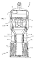
- FIG. 6 is a detailed schematical side elevational view of one possible embodiment of the dirt collection vessel of the present invention.
- FIG. 7 is a detailed side elevational view of an alternative embodiment of a dirt collection vessel incorporating a stepped dirt cup side wall.
- FIG. 8 is a detailed cross sectional view illustrating seven different profiles for ribs provided along the inner surface of the dirt cup side wall such as illustrated in either of FIGS. 4 and 5 .
- the upright vacuum cleaner 10 has a body 12 including a nozzle assembly 14 and a handle assembly 16 .
- the handle assembly 16 includes a control handle 18 and a handgrip 20 .
- a control switch 22 is provided for turning the vacuum cleaner 10 on and off.
- electrical power is supplied to the vacuum cleaner 10 from a standard electrical wall outlet through an electrical cord (not shown).
- the vacuum cleaner 10 could be powered by battery if desired.
- a pair of rear wheels 24 are provided on the lower portion of the handle assembly 16 and a pair of front wheels 25 are provided on the nozzle assembly 14 . Together, these wheels 24 , 25 support the vacuum cleaner 10 for movement across the floor.
- a foot latch 26 functions to lock the handle assembly 16 in an upright position as shown in FIGS. 1-3 . When the foot latch 26 is released, the handle assembly 16 may be pivoted relative to the nozzle assembly 14 as the vacuum cleaner 10 is manipulated back and forth to clean the floor.
- the handle assembly 16 includes a dirt cup receiver 28 adapted to receive and hold the dirt collection vessel 30 .
- the dirt collection vessel 30 may take the form of a dirt cup 32 and cooperating lid 34 .
- the dirt cup 32 includes a dirt collection chamber 36 having an arcuate sidewall 38 , a tangentially directed inlet 40 and an axially directed outlet 42 .
- a shroud 44 is provided in the dirt cup 32 over the axially directed outlet 42 .
- the shroud 44 includes a plurality of fine apertures 46 which allow the passage of clean air yet prevent the passage of course dirt particles and debris.
- the shroud 44 is cylindrical in shape and concentrically received within the cylindrical sidewall 38 of the dirt cup 32 . Such a structural arrangement induces cyclonic airflow in the dirt cup 32 forming a primary cyclone that provides for enhanced cleaning efficiency.
- the dirt collection vessel 30 also includes a secondary cyclone generally designated by reference number 50 .
- the secondary cyclone 50 comprises multiple vortex chambers 52 that are provided in parallel.
- the secondary cyclone 50 generally removes substantially any fine particles remaining in the air stream after it passes through the shroud 44 .
- the nozzle assembly 14 includes a suction inlet 54 .
- a rotary agitator 56 is carried on the nozzle assembly 14 so as to extend across the suction inlet 54 .
- a suction generator 58 including a fan and a cooperating drive motor, is carried on the handle assembly 16 .
- the suction generator 58 functions to generate a vacuum air stream for drawing dirt and debris from the surface to be cleaned.
- the rotary agitator 56 is connected by power take off to the motor of the suction generator 58 . While the suction generator 58 is illustrated as being carried on the handle assembly 16 , it should be appreciated that, alternatively, it could be carried on the nozzle assembly 14 if desired.
- the rotary agitator 56 is driven by the motor of the suction generator 58 and functions to beat dirt and debris from the nap of an underlying carpet.
- the suction generator 58 simultaneously functions to draw a vacuum air stream into the suction inlet 54 . Dirt and debris from the carpet is entrained in the air stream, which is then drawn by the suction generator 58 into the dirt cup 32 of the dirt collection vessel 30 . Dirt and debris is captured in the dirt collection chamber 30 of the dirt cup 32 while relatively clean air is drawn through the shroud 44 . That air stream then passes through the secondary cyclone or fine particle filter 50 before being exhausted through the dirt collection discharge outlet 57 and then passing over the motor of the suction generator 58 to provide cooling. The air is then exhausted through a final filter (not shown), such as a HEPA filter, before being exhausted through an exhaust port 62 into the environment.
- a final filter such as a HEPA filter
- ribbing 60 is provided along the inside surface of the arcuate or cylindrical sidewall 38 of the dirt cup 32 .
- the ribbing may extend upwardly from the bottom wall 64 of the dirt cup 34 to a point even with the bottom of the filter skirt 66 (note area delineated by “A”).
- the ribbing 60 may extend from the bottom wall 64 of the dirt cup 32 to the top of the dirt cup (note area delineated by “B”).
- other ribbing arrangements are possible.
- the ribbing 60 may extend vertically: that is, substantially perpendicular to the bottom wall 64 of the dirt cup 32 .
- the ribbing 60 may extend horizontally: that is, parallel to the bottom wall 64 of the dirt cup 32 .
- the ribbing may also extend helically, spiraling downwardly in the direction of air flow from the inlet 40 toward the bottom wall 64 of the dirt cup 32 .
- the channel 74 provided between the rib 60 is wider at the top near the inlet 40 and gradually narrows until a point adjacent the skirt 72 . From that point until the bottom wall 64 , the channel 74 is approximately the same width.
- the side wall 38 is continuous.
- the arcuate or cylindrical side wall 38 includes a step 70 .
- the step 70 may be provided at a point along the side wall 38 substantially opposite the skirt 72 at the bottom of the shroud 44 .
- the ribbing 60 may extend from the step 70 to the bottom wall 64 or from the inlet 40 , past the step 70 to the bottom wall 64 .
- the helical ribbing 60 is provided above the step 70 and vertical ribbing 60 ′ is provided below the step.
- various rib 60 profiles may be provided including, but not limited to, wave shape, curl shape, wall shape, plateau shape and cove shape.
- the surfaces of the rib 60 are smooth.
- the rib 60 may also have a sloped leading edge 62 (relative to air stream flow) forming an angle with the side wall 38 of between approximately 30 and 60 degrees.
- Each rib 60 may have a height of between about 0.5 and about 3.0 mm.
- the ribs 60 may have a spacing between ribs of between about 1.0 and about 25 mm. Further, the rib spacing to rib height ratio is typically between 3.0 to 15.0.
- the channels 74 formed between the ribs 60 have a cross sectional area of between about 13 and about 50 mm 2 .
- the ribbing 60 functions to increase the performance and cleaning efficiency of the vacuum cleaner 10 by better separating dirt and debris from the air stream.
Landscapes
- Engineering & Computer Science (AREA)
- Mechanical Engineering (AREA)
- Filters For Electric Vacuum Cleaners (AREA)
- Accommodation For Nursing Or Treatment Tables (AREA)
- Lock And Its Accessories (AREA)
Abstract
Description
Claims (17)
Priority Applications (1)
| Application Number | Priority Date | Filing Date | Title |
|---|---|---|---|
| US13/381,279 US8898856B2 (en) | 2010-11-09 | 2011-11-09 | Dirt cup with secondary cyclonic cleaning chambers |
Applications Claiming Priority (3)
| Application Number | Priority Date | Filing Date | Title |
|---|---|---|---|
| US41165910P | 2010-11-09 | 2010-11-09 | |
| US13/381,279 US8898856B2 (en) | 2010-11-09 | 2011-11-09 | Dirt cup with secondary cyclonic cleaning chambers |
| PCT/US2011/059913 WO2012064814A1 (en) | 2010-11-09 | 2011-11-09 | Dirt cup with secondary cyclonic cleaning chambers |
Publications (2)
| Publication Number | Publication Date |
|---|---|
| US20130219654A1 US20130219654A1 (en) | 2013-08-29 |
| US8898856B2 true US8898856B2 (en) | 2014-12-02 |
Family
ID=46050197
Family Applications (2)
| Application Number | Title | Priority Date | Filing Date |
|---|---|---|---|
| US13/291,590 Expired - Fee Related US8336136B1 (en) | 2010-11-09 | 2011-11-08 | Panel assembly for a partial drop-side crib |
| US13/381,279 Expired - Fee Related US8898856B2 (en) | 2010-11-09 | 2011-11-09 | Dirt cup with secondary cyclonic cleaning chambers |
Family Applications Before (1)
| Application Number | Title | Priority Date | Filing Date |
|---|---|---|---|
| US13/291,590 Expired - Fee Related US8336136B1 (en) | 2010-11-09 | 2011-11-08 | Panel assembly for a partial drop-side crib |
Country Status (3)
| Country | Link |
|---|---|
| US (2) | US8336136B1 (en) |
| CA (1) | CA2758037C (en) |
| WO (1) | WO2012064814A1 (en) |
Cited By (7)
| Publication number | Priority date | Publication date | Assignee | Title |
|---|---|---|---|---|
| US9885194B1 (en) | 2017-05-11 | 2018-02-06 | Hayward Industries, Inc. | Pool cleaner impeller subassembly |
| US9885196B2 (en) | 2015-01-26 | 2018-02-06 | Hayward Industries, Inc. | Pool cleaner power coupling |
| US9896858B1 (en) | 2017-05-11 | 2018-02-20 | Hayward Industries, Inc. | Hydrocyclonic pool cleaner |
| US9909333B2 (en) | 2015-01-26 | 2018-03-06 | Hayward Industries, Inc. | Swimming pool cleaner with hydrocyclonic particle separator and/or six-roller drive system |
| US10156083B2 (en) | 2017-05-11 | 2018-12-18 | Hayward Industries, Inc. | Pool cleaner power coupling |
| US20190134649A1 (en) * | 2017-07-05 | 2019-05-09 | Oneida Air Systems, Inc. | Low-Profile, High-Pressure Dust Separator and Collector |
| US20230249111A1 (en) * | 2020-06-03 | 2023-08-10 | York (Wuxi) Air Conditioning And Refrigeration Co., Ltd. | Gas-liquid separator |
Families Citing this family (17)
| Publication number | Priority date | Publication date | Assignee | Title |
|---|---|---|---|---|
| US20170367497A1 (en) * | 2016-06-28 | 2017-12-28 | Breathablebaby, Llc | Porous crib shield system |
| US20170367496A1 (en) | 2016-06-28 | 2017-12-28 | Breathablebaby, Llc | Durable crib shield system |
| US10694868B2 (en) | 2016-06-28 | 2020-06-30 | Breathablebaby, Llc | Layered crib shield system |
| US10722049B2 (en) | 2016-06-28 | 2020-07-28 | Breathablebaby, Llc | Reversible crib shield system |
| US8997310B2 (en) * | 2012-10-12 | 2015-04-07 | Electrolux Home Care Products, Inc. | Vacuum cleaner cyclone with helical cyclone expansion region |
| USD689658S1 (en) | 2012-12-12 | 2013-09-10 | Electrolux Home Care Products, Inc. | Exterior surface of a cyclone receptacle |
| US8978199B2 (en) | 2013-02-01 | 2015-03-17 | Bissell Homecare, Inc. | Vacuum cleaner with debris collector |
| US11166607B2 (en) | 2016-03-31 | 2021-11-09 | Lg Electronics Inc. | Cleaner |
| EP4413908A3 (en) | 2016-03-31 | 2024-11-27 | LG Electronics Inc. | Cleaning apparatus |
| KR102560970B1 (en) * | 2016-03-31 | 2023-07-31 | 엘지전자 주식회사 | Cleaner |
| GB2554929B (en) * | 2016-10-14 | 2022-03-02 | Techtronic Floor Care Tech Ltd | Cyclonic separation device |
| CN214631951U (en) * | 2019-08-28 | 2021-11-09 | 尚科宁家运营有限公司 | Debris fins and dust cups for robotic cleaner dust cups |
| USD942770S1 (en) * | 2021-04-02 | 2022-02-08 | Guangzhou Dengfeng Luggage Co., Ltd | Portable foldable crib |
| USD975994S1 (en) * | 2021-04-16 | 2023-01-24 | Shenzhen Create Future International Trading Company | Baby changing backpack |
| USD971591S1 (en) * | 2021-04-22 | 2022-12-06 | Quanzhou Beisisaile Technology Co., Ltd. | Folding crib diaper backpack |
| USD971592S1 (en) * | 2021-06-09 | 2022-12-06 | Dongguan Miku Keji Co., Ltd. | Backpack for carrying baby |
| US20240374049A1 (en) * | 2023-05-12 | 2024-11-14 | Jennifer Butler | Infant Crib |
Citations (22)
| Publication number | Priority date | Publication date | Assignee | Title |
|---|---|---|---|---|
| US468935A (en) * | 1892-02-16 | Orville m | ||
| US814837A (en) * | 1904-11-08 | 1906-03-18 | Ephraim H Fenton | Pneumatic dust removing and collecting apparatus. |
| US2010128A (en) * | 1931-09-17 | 1935-08-06 | Gerald D Arnold | Centrifugal separator |
| US2222930A (en) * | 1939-04-14 | 1940-11-26 | Gerald D Arnold | Centrifugal separator |
| US2351864A (en) * | 1940-06-27 | 1944-06-20 | Jr Garrett B Linderman | Dust collector |
| US2378600A (en) * | 1940-09-09 | 1945-06-19 | Hermannus Van Tongeren | Centrifugal dust separator |
| US2542635A (en) * | 1948-01-27 | 1951-02-20 | Apex Electrical Mfg Co | Centrifugal dust separator |
| US3399770A (en) * | 1966-01-19 | 1968-09-03 | Beloit Corp | Method for centrifugal separation of particles from a mixture |
| US3513642A (en) * | 1968-07-25 | 1970-05-26 | Milan S Cornett | Centrifugal dust separator |
| US3577711A (en) * | 1969-06-02 | 1971-05-04 | Us Agriculture | Apparatus for removing entrained particles from gases |
| US5137554A (en) * | 1991-09-09 | 1992-08-11 | Fasco Industries, Inc. | Cyclonic vacuum cleaner cone |
| US20050066469A1 (en) * | 2003-09-30 | 2005-03-31 | Samsung Gwangju Electronics Co., Ltd. | Cyclone dust collecting apparatus for vacuum cleaner |
| US20050138759A1 (en) * | 2003-12-27 | 2005-06-30 | Lg Electronics Inc. | Dust collector of vacuum cleaner |
| US20050172585A1 (en) * | 2004-02-11 | 2005-08-11 | Jang-Keun Oh | Cyclone dust collecting apparatus for a vacuum cleaner |
| US20060042206A1 (en) * | 2004-08-26 | 2006-03-02 | Arnold Adrian C | Compact cyclonic separation device |
| US20060230718A1 (en) * | 2005-03-29 | 2006-10-19 | Samsung Gwangju Electronics Co., Ltd. | Dust-separating apparatus for vacuum cleaner |
| US20070163073A1 (en) * | 2006-01-19 | 2007-07-19 | Arnold Sepke | Vacuum cleaner dustcup and conduit construction |
| US20080155948A1 (en) * | 2006-12-22 | 2008-07-03 | David Benjamin Smith | Cyclonic Separation Apparatus |
| US7419522B2 (en) * | 2005-03-18 | 2008-09-02 | Euro-Pro Operating, Llc | Dirt separation and collection assembly for vacuum cleaner |
| US20090007369A1 (en) * | 2007-07-05 | 2009-01-08 | Dyson Technology Limited | Cyclonic separating apparatus |
| US20090300874A1 (en) * | 2008-06-05 | 2009-12-10 | Bissell Homecare, Inc. | Cyclonic vacuum cleaner with improved collection chamber |
| US7922794B2 (en) | 2008-10-08 | 2011-04-12 | Electrolux Home Care Products, Inc. | Cyclonic vacuum cleaner ribbed cyclone shroud |
Family Cites Families (19)
| Publication number | Priority date | Publication date | Assignee | Title |
|---|---|---|---|---|
| US1695571A (en) * | 1927-04-23 | 1928-12-18 | E M Trimble Mfg Co Inc | Crib |
| US4359792A (en) | 1980-01-17 | 1982-11-23 | Dale Clara M | Crib |
| US4530528A (en) | 1983-02-22 | 1985-07-23 | Louis Shamie | Double action crib drop side lock |
| US4535493A (en) | 1984-04-27 | 1985-08-20 | Gem Industries, Inc. | Crib drop side latch |
| US4703524A (en) * | 1984-12-28 | 1987-11-03 | Simmons Universal Corporation | Crib |
| US4768243A (en) | 1987-10-09 | 1988-09-06 | The Quaker Oats Company | Latch for a drop side crib |
| US4924539A (en) | 1989-10-17 | 1990-05-15 | Benoit Roland A | Child's crib |
| CA2034366A1 (en) | 1990-10-19 | 1992-04-20 | Norma Bellini | Crib with drop-side |
| CA2302066C (en) | 1999-04-08 | 2006-07-18 | Gem Industries, Inc. | Child's crib |
| US6596044B1 (en) * | 2000-03-06 | 2003-07-22 | The Hoover Company | Dirt collecting system for a vacuum cleaner |
| US6349761B1 (en) * | 2000-12-27 | 2002-02-26 | Industrial Technology Research Institute | Fin-tube heat exchanger with vortex generator |
| US6505360B2 (en) | 2001-04-06 | 2003-01-14 | Hickory Springs Manufacturing Company | Crib with drop side, and guiding and locking mechanism therefor |
| US6704951B2 (en) | 2001-07-03 | 2004-03-16 | Community Products, Llc | Crib |
| US20050081321A1 (en) * | 2003-10-15 | 2005-04-21 | Milligan Michael A. | Hand-held cordless vacuum cleaner |
| WO2005041739A1 (en) * | 2003-10-22 | 2005-05-12 | Bissell Homecare, Inc. | Vacuum cleaner with cyclonic dirt separation and bottom discharge dirt cup with filter |
| US7062806B2 (en) | 2004-04-28 | 2006-06-20 | Katherine Merlin | Bedding structure with improved door/tracking system |
| US7918909B2 (en) * | 2004-09-01 | 2011-04-05 | Bissell Homecare, Inc. | Cyclone separator with fine particle separation member |
| US7415740B1 (en) | 2007-05-08 | 2008-08-26 | Kemper Gary M | Safety bed |
| US7752689B1 (en) * | 2008-12-09 | 2010-07-13 | Delta Enterprise Corp. | Crib with pivoting and sliding drop side rail |
-
2011
- 2011-11-08 US US13/291,590 patent/US8336136B1/en not_active Expired - Fee Related
- 2011-11-08 CA CA2758037A patent/CA2758037C/en active Active
- 2011-11-09 US US13/381,279 patent/US8898856B2/en not_active Expired - Fee Related
- 2011-11-09 WO PCT/US2011/059913 patent/WO2012064814A1/en not_active Ceased
Patent Citations (23)
| Publication number | Priority date | Publication date | Assignee | Title |
|---|---|---|---|---|
| US468935A (en) * | 1892-02-16 | Orville m | ||
| US814837A (en) * | 1904-11-08 | 1906-03-18 | Ephraim H Fenton | Pneumatic dust removing and collecting apparatus. |
| US2010128A (en) * | 1931-09-17 | 1935-08-06 | Gerald D Arnold | Centrifugal separator |
| US2222930A (en) * | 1939-04-14 | 1940-11-26 | Gerald D Arnold | Centrifugal separator |
| US2351864A (en) * | 1940-06-27 | 1944-06-20 | Jr Garrett B Linderman | Dust collector |
| US2378600A (en) * | 1940-09-09 | 1945-06-19 | Hermannus Van Tongeren | Centrifugal dust separator |
| US2542635A (en) * | 1948-01-27 | 1951-02-20 | Apex Electrical Mfg Co | Centrifugal dust separator |
| US3399770A (en) * | 1966-01-19 | 1968-09-03 | Beloit Corp | Method for centrifugal separation of particles from a mixture |
| US3513642A (en) * | 1968-07-25 | 1970-05-26 | Milan S Cornett | Centrifugal dust separator |
| US3577711A (en) * | 1969-06-02 | 1971-05-04 | Us Agriculture | Apparatus for removing entrained particles from gases |
| US5137554A (en) * | 1991-09-09 | 1992-08-11 | Fasco Industries, Inc. | Cyclonic vacuum cleaner cone |
| US20050066469A1 (en) * | 2003-09-30 | 2005-03-31 | Samsung Gwangju Electronics Co., Ltd. | Cyclone dust collecting apparatus for vacuum cleaner |
| US20050138759A1 (en) * | 2003-12-27 | 2005-06-30 | Lg Electronics Inc. | Dust collector of vacuum cleaner |
| US20050172585A1 (en) * | 2004-02-11 | 2005-08-11 | Jang-Keun Oh | Cyclone dust collecting apparatus for a vacuum cleaner |
| US20060042206A1 (en) * | 2004-08-26 | 2006-03-02 | Arnold Adrian C | Compact cyclonic separation device |
| US7419522B2 (en) * | 2005-03-18 | 2008-09-02 | Euro-Pro Operating, Llc | Dirt separation and collection assembly for vacuum cleaner |
| US20060230718A1 (en) * | 2005-03-29 | 2006-10-19 | Samsung Gwangju Electronics Co., Ltd. | Dust-separating apparatus for vacuum cleaner |
| US20070163073A1 (en) * | 2006-01-19 | 2007-07-19 | Arnold Sepke | Vacuum cleaner dustcup and conduit construction |
| US20080155948A1 (en) * | 2006-12-22 | 2008-07-03 | David Benjamin Smith | Cyclonic Separation Apparatus |
| US20090007369A1 (en) * | 2007-07-05 | 2009-01-08 | Dyson Technology Limited | Cyclonic separating apparatus |
| US20090300874A1 (en) * | 2008-06-05 | 2009-12-10 | Bissell Homecare, Inc. | Cyclonic vacuum cleaner with improved collection chamber |
| US20090300872A1 (en) * | 2008-06-05 | 2009-12-10 | Bissell Homecare, Inc. | Cyclonic vacuum cleaner with improved filter cartridge |
| US7922794B2 (en) | 2008-10-08 | 2011-04-12 | Electrolux Home Care Products, Inc. | Cyclonic vacuum cleaner ribbed cyclone shroud |
Cited By (13)
| Publication number | Priority date | Publication date | Assignee | Title |
|---|---|---|---|---|
| US11236523B2 (en) | 2015-01-26 | 2022-02-01 | Hayward Industries, Inc. | Pool cleaner with cyclonic flow |
| US9885196B2 (en) | 2015-01-26 | 2018-02-06 | Hayward Industries, Inc. | Pool cleaner power coupling |
| US9909333B2 (en) | 2015-01-26 | 2018-03-06 | Hayward Industries, Inc. | Swimming pool cleaner with hydrocyclonic particle separator and/or six-roller drive system |
| US10557278B2 (en) | 2015-01-26 | 2020-02-11 | Hayward Industries, Inc. | Pool cleaner with cyclonic flow |
| US12065854B2 (en) | 2015-01-26 | 2024-08-20 | Hayward Industries, Inc. | Pool cleaner with cyclonic flow |
| US9896858B1 (en) | 2017-05-11 | 2018-02-20 | Hayward Industries, Inc. | Hydrocyclonic pool cleaner |
| US10156083B2 (en) | 2017-05-11 | 2018-12-18 | Hayward Industries, Inc. | Pool cleaner power coupling |
| US10253517B2 (en) | 2017-05-11 | 2019-04-09 | Hayward Industries, Inc. | Hydrocyclonic pool cleaner |
| US10767382B2 (en) | 2017-05-11 | 2020-09-08 | Hayward Industries, Inc. | Pool cleaner impeller subassembly |
| US9885194B1 (en) | 2017-05-11 | 2018-02-06 | Hayward Industries, Inc. | Pool cleaner impeller subassembly |
| US20190134649A1 (en) * | 2017-07-05 | 2019-05-09 | Oneida Air Systems, Inc. | Low-Profile, High-Pressure Dust Separator and Collector |
| US20230249111A1 (en) * | 2020-06-03 | 2023-08-10 | York (Wuxi) Air Conditioning And Refrigeration Co., Ltd. | Gas-liquid separator |
| US12508526B2 (en) * | 2020-06-03 | 2025-12-30 | York (Wuxi) Air Conditioning And Refrigeration Co., Ltd. | Gas-liquid separator |
Also Published As
| Publication number | Publication date |
|---|---|
| US20130219654A1 (en) | 2013-08-29 |
| CA2758037A1 (en) | 2012-05-09 |
| CA2758037C (en) | 2018-11-20 |
| US8336136B1 (en) | 2012-12-25 |
| WO2012064814A1 (en) | 2012-05-18 |
Similar Documents
| Publication | Publication Date | Title |
|---|---|---|
| US8898856B2 (en) | Dirt cup with secondary cyclonic cleaning chambers | |
| US9681787B2 (en) | Dual stage cyclone vacuum cleaner | |
| US20110023261A1 (en) | Filterless and bagless vacuum cleaner incorporating a sling shot separator | |
| US7887613B2 (en) | Vacuum cleaner having dirt collection vessel with toroidal cyclone | |
| US8209815B2 (en) | Dual stage cyclonic dust collector | |
| US8533903B2 (en) | Dirt cup assembly with a pre-filter having a plurality of ribs | |
| US8726461B2 (en) | Dual stage cyclonic vacuum cleaner | |
| US6607572B2 (en) | Cyclonic separating apparatus | |
| US7581287B2 (en) | Vacuum cleaner with spiral air guide | |
| WO2008070969A1 (en) | Surface cleaning apparatus with off-centre dirt bin inlet | |
| US20100269289A1 (en) | Internal air separators in a dirt separation device | |
| US20090193613A1 (en) | Dirt cup with secondary cyclonic cleaning chambers | |
| JP6291218B2 (en) | Electric vacuum cleaner | |
| WO2009073888A1 (en) | Dual stage cyclonic dust collector | |
| US20090178237A1 (en) | Vacuum cleaner with spiral air guide | |
| US20100186189A1 (en) | Vacuum cleaner having dirt collection vessel with a labyrinthine air flow path | |
| CA2794909C (en) | Pre-filter or shroud with helical stepped wall | |
| CA2461879C (en) | Nozzle assembly with air flow acceleration channels | |
| GB2498450A (en) | Bag compartment of a vacuum cleaner | |
| CN102599851A (en) | Motor box structure for lowering noise of motor | |
| JP6178214B2 (en) | Electric vacuum cleaner | |
| CA2263011C (en) | Vacuum cleaner with three stage air induction system |
Legal Events
| Date | Code | Title | Description |
|---|---|---|---|
| AS | Assignment |
Owner name: PANASONIC CORPORATION OF NORTH AMERICA, NEW JERSEY Free format text: ASSIGNMENT OF ASSIGNORS INTEREST;ASSIGNOR:RUBEN, BRIAN K.;REEL/FRAME:027946/0073 Effective date: 20111222 |
|
| FEPP | Fee payment procedure |
Free format text: MAINTENANCE FEE REMINDER MAILED (ORIGINAL EVENT CODE: REM.) |
|
| LAPS | Lapse for failure to pay maintenance fees |
Free format text: PATENT EXPIRED FOR FAILURE TO PAY MAINTENANCE FEES (ORIGINAL EVENT CODE: EXP.); ENTITY STATUS OF PATENT OWNER: LARGE ENTITY |
|
| STCH | Information on status: patent discontinuation |
Free format text: PATENT EXPIRED DUE TO NONPAYMENT OF MAINTENANCE FEES UNDER 37 CFR 1.362 |
|
| FP | Lapsed due to failure to pay maintenance fee |
Effective date: 20181202 |