US8897936B2 - Device for stabilising the guidance of a vehicle - Google Patents
Device for stabilising the guidance of a vehicle Download PDFInfo
- Publication number
- US8897936B2 US8897936B2 US13/518,204 US201013518204A US8897936B2 US 8897936 B2 US8897936 B2 US 8897936B2 US 201013518204 A US201013518204 A US 201013518204A US 8897936 B2 US8897936 B2 US 8897936B2
- Authority
- US
- United States
- Prior art keywords
- wheel
- vehicle
- friction
- dynamic friction
- static friction
- Prior art date
- Legal status (The legal status is an assumption and is not a legal conclusion. Google has not performed a legal analysis and makes no representation as to the accuracy of the status listed.)
- Active
Links
Images


Classifications
-
- B—PERFORMING OPERATIONS; TRANSPORTING
- B64—AIRCRAFT; AVIATION; COSMONAUTICS
- B64C—AEROPLANES; HELICOPTERS
- B64C25/00—Alighting gear
- B64C25/32—Alighting gear characterised by elements which contact the ground or similar surface
- B64C25/50—Steerable undercarriages; Shimmy-damping
Definitions
- the invention relates to a device for stabilizing the guidance of an aircraft, the aircraft having at least one wheel which is arranged in such a way that it can be turned relative to the longitudinal axis of the vehicle, and steering means that interact with the at least one wheel and are designed to guide the vehicle by turning the at least one wheel.
- Aircraft are designed to travel through the air, i.e. the structure thereof is optimized for air as a medium.
- the undercarriage of an aircraft serves to enable the aircraft to move safely and comfortably even in contact with the ground.
- the undercarriage is also used for landing or starting the aircraft, i.e. for transferring the aircraft from or to the proper medium for its movement.
- ground contact is reduced to a relatively small area in relation to the weight and size of the aircraft by the wheels arranged on the undercarriage, and therefore, due to poor weather conditions, for example, and the resulting poor condition of the runway, a risk to safety may arise.
- U.S. Pat. No. 6,722,610 B1 has disclosed a steerable undercarriage for aircraft which, in the case of a crosswind landing by the De-Crab method, aligns the wheels of the undercarriage in the direction of motion of the aircraft, thus allowing the aircraft to land safely on the runway at the correction angle required by the crosswind without the pilot turning the longitudinal axis of the aircraft in the direction of motion beforehand, this being regarded as the most critical moment in such a crosswind landing. Any transverse forces on the undercarriage of the aircraft can thus be avoided.
- the abovementioned patent document furthermore describes a method for increasing the braking effect after the aircraft touches down by turning the pivotably arranged wheels of the undercarriage by such an angle over the direction of motion of the vehicle that abrasion of the rubber of the wheels is increased.
- This is supposed to ensure that the aircraft slows down more quickly or that deceleration increases owing to the increased friction between the ground covering and the tires.
- the static friction between the ground covering and the tires which is necessary for ground contact, may change to dynamic friction, this being referred to colloquially as skidding and leading to the aircraft becoming unstable and no longer having acceptable maneuverability.
- the object is achieved, using the initially mentioned device for guidance stabilization, by virtue of the fact that the device has a detecting unit, which is designed to detect an at least partial transition from static friction to dynamic friction between the at least one wheel and a ground covering, and the device furthermore has a control unit, which, when the detecting unit detects the transition from static friction to dynamic friction, is designed to turn the at least one wheel by means of the steering means in such a way that the dynamic friction between the wheel and the ground covering changes back to static friction.
- turning the wheel provided for guiding the vehicle is understood to mean turning in such a way that the wheel is turned or pivoted relative to the longitudinal axis of the vehicle, the turning or pivoting axis being substantially parallel to the yaw or vertical axis of the vehicle.
- the present invention uses an appropriate detecting unit to detect the at least partial transition from static friction to dynamic friction between the at least one wheel and the ground covering, something which can occur, for example, when the wheel is acted upon by relevant transverse forces, which lead to a loss of wheel adhesion. The wheel would thus begin to skid.
- the detecting unit detects skidding or the transition from static friction to dynamic friction
- an intervention is made in the steering by means of a control unit in such a way that the wheels are turned and thus the direction of running thereof is modified, ensuring that the dynamic friction between the wheel and the ground covering changes back to static friction.
- This is advantageous, for example, particularly when the steering means provided for turning the wheels are connected to an automatic steering system for automating the guidance of the vehicle.
- the major advantage here is that a skidding vehicle is automatically brought back into a state in which it has appropriate ground adhesion and is thus made steerable again. It is thereby possible to significantly increase the safety of a vehicle in the case of correspondingly extreme weather conditions, for example.
- the control unit turns the wheels with the aid of the steering means in such a way that the direction of running of the wheels is aligned in the direction of motion.
- the direction of motion can be determined with the aid of a GNS system, for example.
- the wheels are then turned in the direction of skidding, with the result that they can make a transition back from dynamic friction to static friction, and hence the vehicle once again has appropriate ground adhesion.
- the detecting unit is furthermore designed to detect a reverse transition from dynamic friction to static friction between the wheel and the ground covering, thus making it possible correspondingly to detect when the wheel again has ground adhesion to enable the vehicle to be guided. This makes it possible to ensure that the wheels cannot be turned back as far as the direction of motion of the vehicle but only until there is once again static friction between the wheel and the ground covering.
- the transition from static to dynamic friction and the reverse transition from dynamic to static friction can advantageously be determined in such a way that a sensor for measuring the speed of rotation is arranged on the wheel, a transition being detected when a theoretical vehicle speed correlated with the speed of rotation of the wheel deviates from the actual vehicle speed, which can likewise be determined by means of a GNS system, for example.
- the speed of rotation of the wheel correlates with the vehicle speed, a transition from static to dynamic friction being detected when the theoretical vehicle speed obtained from the speed of rotation is less than the actual vehicle speed. If the theoretical speed obtained from the speed of rotation of the wheel is 0, the wheel is locked up.
- the transition from static to dynamic friction or the reverse transition can advantageously also be determined according to the steering angle relative to the longitudinal axis of the vehicle and the actual direction of motion. If the actual direction of motion of the vehicle deviates from the theoretical direction of motion which ought to result from the steering angle, it is possible to infer that the wheel or wheels is/are losing ground adhesion and are skidding, it thus being possible to assume dynamic friction between the ground covering and the wheel.
- the present invention is suitable particularly for aircraft which have a steerable undercarriage and turn their undercarriage in a particular direction after landing or touchdown of the aircraft on the runway in order to steer the aircraft during the rollout phase.
- the wheels may lose adhesion and begin to skid, with the result that the guidance stability of the aircraft is limited.
- the wheels recover adhesion and, as a result, the brakes also work more effectively.
- FIG. 1 shows a schematic representation of a landed aircraft with skidding tires
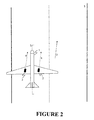
- FIG. 2 shows a schematic representation of a landed aircraft with corresponding ground adhesion
- FIG. 3 shows a schematic representation of the device.
- FIG. 1 shows schematically a landed aircraft 1 , the undercarriage (steering means) of which and hence also the wheels 2 of the main undercarriage have been turned in the direction of the center of the runway 3 in order to guide the aircraft 1 in this direction shortly after touchdown.
- the direction of running of the wheels 2 is indicated by the dashed arrows 4 and deviates from the actual direction of motion 5 of the aircraft 1 .
- the device With the aid of the detecting unit, the device then detects this state, i.e. the transition from static to dynamic friction, and initiates appropriate measures.
- the control unit By means of the control unit according to the invention, the undercarriage with its wheels 2 is then turned in such a way that the direction of running 4 of the wheels 2 is turned in the direction of motion until the dynamic friction between the wheels 2 and the runway 3 changes back to static friction and the aircraft 1 again has appropriate adhesion. This is illustrated schematically in FIG. 2 .
- the wheels 2 as illustrated in FIG. 2 , have been turned until the dynamic friction has changed back to static friction. However, the wheels have not been turned until they are aligned parallel to the longitudinal axis of the aircraft but only until there is static friction again.
- the aircraft 1 then begins immediately with guidance in the then prevailing direction 5 , and the aircraft is therefore stabilized and can be steered and braked safely.
- FIG. 3 shows a schematic representation of the device 10 .
- the device has two wheels 2 in order to guide a vehicle (not shown) in a particular direction or in order to ensure so-called transverse guidance of the vehicle.
- the wheels 2 can be turned or pivoted relative to the longitudinal axis of the vehicle, this being accomplished by means of appropriate steering means (not shown), which are sufficiently well known from the prior art.
- the device 10 furthermore has a detecting unit 12 , which is designed to detect a transition from static friction to dynamic friction between the wheels 2 and the ground covering 3 in contact with said wheels 2 .
- This detection can be accomplished, for example, with the aid of a rotation sensor, which continuously measures the speed of rotation of the wheels 2 and, if there is a deviation between the actual vehicle speed and a theoretical vehicle speed correlated with the speed of rotation of the wheels 2 , infers a transition from static to dynamic friction and vice versa.
- the detecting unit 12 is furthermore connected to a control unit 11 , which is designed to turn the wheels with the aid of the steering means. If the detecting unit 12 detects a transition from static to dynamic friction, i.e. skidding of the wheels 2 , it communicates this fact to the control unit 11 , with the result that the control unit 11 then turns the wheels 2 in the direction of the longitudinal axis of the vehicle, for example, thus enabling the wheels 2 to regain ground adhesion, that is to say allowing a transition to take place from dynamic friction to static friction.
Landscapes
- Engineering & Computer Science (AREA)
- Mechanical Engineering (AREA)
- Aviation & Aerospace Engineering (AREA)
- Regulating Braking Force (AREA)
- Control Of Driving Devices And Active Controlling Of Vehicle (AREA)
- Steering Control In Accordance With Driving Conditions (AREA)
Abstract
Description
Claims (5)
Applications Claiming Priority (4)
| Application Number | Priority Date | Filing Date | Title |
|---|---|---|---|
| DE200910060562 DE102009060562A1 (en) | 2009-12-23 | 2009-12-23 | Device for guiding stabilization of a vehicle |
| DE102009060562 | 2009-12-23 | ||
| DE102009060562.2 | 2009-12-23 | ||
| PCT/EP2010/007810 WO2011079924A1 (en) | 2009-12-23 | 2010-12-21 | Device for stabilizing the guidance of a vehicle |
Publications (2)
| Publication Number | Publication Date |
|---|---|
| US20120310452A1 US20120310452A1 (en) | 2012-12-06 |
| US8897936B2 true US8897936B2 (en) | 2014-11-25 |
Family
ID=43857893
Family Applications (1)
| Application Number | Title | Priority Date | Filing Date |
|---|---|---|---|
| US13/518,204 Active US8897936B2 (en) | 2009-12-23 | 2010-12-21 | Device for stabilising the guidance of a vehicle |
Country Status (4)
| Country | Link |
|---|---|
| US (1) | US8897936B2 (en) |
| EP (1) | EP2516266B1 (en) |
| DE (1) | DE102009060562A1 (en) |
| WO (1) | WO2011079924A1 (en) |
Families Citing this family (4)
| Publication number | Priority date | Publication date | Assignee | Title |
|---|---|---|---|---|
| US10106249B2 (en) * | 2011-02-04 | 2018-10-23 | Borealis Technical Limited | Method of operating aircraft drive to move an aircraft under adverse ground conditions |
| FR2982582B1 (en) * | 2011-11-10 | 2013-12-13 | Messier Bugatti Dowty | (EN) ORIENTATION REAGENT METHOD FOR AN AIRCRAFT AIRCRAFT COMPRISING AN EASILY ORIENTABLE PART. |
| CN113753226A (en) * | 2021-08-18 | 2021-12-07 | 西安航空制动科技有限公司 | Integrated embedded aircraft braking system |
| CN114013636B (en) * | 2021-11-02 | 2023-02-10 | 西安航空制动科技有限公司 | Method for analyzing and simulating antiskid failure of airplane wheel braking system |
Citations (3)
| Publication number | Priority date | Publication date | Assignee | Title |
|---|---|---|---|---|
| US20060071547A1 (en) * | 2004-09-30 | 2006-04-06 | Eaton Corporation | Valve assembly for anti-skid aircraft brakes |
| WO2006096446A2 (en) * | 2005-03-01 | 2006-09-14 | Borealis Technical Limited | Motor controller |
| WO2007110566A1 (en) | 2006-03-27 | 2007-10-04 | Airbus Uk Limited | Aircraft steering angle warning system |
Family Cites Families (4)
| Publication number | Priority date | Publication date | Assignee | Title |
|---|---|---|---|---|
| US6722610B1 (en) | 2002-11-25 | 2004-04-20 | The Boeing Company | Method, system, and computer program product for controlling maneuverable wheels on a vehicle |
| US7281684B2 (en) * | 2005-02-23 | 2007-10-16 | The Boeing Company | Systems and methods for braking aircraft, including braking intermediate main gears and differential braking |
| US8016366B2 (en) * | 2006-06-02 | 2011-09-13 | Goodrich Corporation | Differential brake control and weighted average wheel speed for brake control system |
| WO2009089551A2 (en) * | 2008-01-11 | 2009-07-16 | General Atomics | Braking system with linear actuator |
-
2009
- 2009-12-23 DE DE200910060562 patent/DE102009060562A1/en not_active Withdrawn
-
2010
- 2010-12-21 WO PCT/EP2010/007810 patent/WO2011079924A1/en not_active Ceased
- 2010-12-21 EP EP20100803233 patent/EP2516266B1/en active Active
- 2010-12-21 US US13/518,204 patent/US8897936B2/en active Active
Patent Citations (3)
| Publication number | Priority date | Publication date | Assignee | Title |
|---|---|---|---|---|
| US20060071547A1 (en) * | 2004-09-30 | 2006-04-06 | Eaton Corporation | Valve assembly for anti-skid aircraft brakes |
| WO2006096446A2 (en) * | 2005-03-01 | 2006-09-14 | Borealis Technical Limited | Motor controller |
| WO2007110566A1 (en) | 2006-03-27 | 2007-10-04 | Airbus Uk Limited | Aircraft steering angle warning system |
Also Published As
| Publication number | Publication date |
|---|---|
| US20120310452A1 (en) | 2012-12-06 |
| EP2516266B1 (en) | 2015-04-29 |
| WO2011079924A1 (en) | 2011-07-07 |
| EP2516266A1 (en) | 2012-10-31 |
| DE102009060562A1 (en) | 2011-06-30 |
Similar Documents
| Publication | Publication Date | Title |
|---|---|---|
| US11235747B2 (en) | Method for controlling a steering system of a vehicle | |
| KR102429180B1 (en) | Vehicle stability control system and method for the same | |
| US10661827B2 (en) | Motor vehicle for piloted driving comprising a front axle steering system and a rear axle steering system | |
| US8781684B2 (en) | Steering and control systems for a three-wheeled vehicle | |
| CN107650893B (en) | Heavy vehicle cornering braking stability assist control system | |
| US9315177B2 (en) | Antilock braking system with directional control | |
| US20130015290A1 (en) | Method of managing the steering of aircraft wheels, in particular in the event of a tire bursting or deflating | |
| US8897936B2 (en) | Device for stabilising the guidance of a vehicle | |
| CN105857586B (en) | Method and apparatus for controlling steerable landing gear | |
| KR102067914B1 (en) | Method for assisting drivers in the event of aquaplaning on a road surface | |
| CN106335634B (en) | Aircraft, steering system, steering method and steering system controller thereof | |
| AU2015306430A1 (en) | Method and device for preventing a cyclist from falling | |
| CN120457067A (en) | Vehicle control method with steering angle correction | |
| US9205866B2 (en) | Steering control apparatus and method | |
| US9199728B2 (en) | Control device for aircraft | |
| EP2567873B1 (en) | Systems and methods for improved aircraft braking | |
| KR102080978B1 (en) | The Safety Driving Method by Controlling Motor and Engine of the Vehicle | |
| CN207535885U (en) | Heavy vehicle brakeing during cornereing stability supplementary controlled system | |
| EP2562059B1 (en) | Method and arrangement for assisting a driver of a vehicle to turn the vehicle when driving during glare ice conditions | |
| JP5460325B2 (en) | A device for correcting the course of an automobile, comprising: first means for selectively braking the wheel; and second means for turning the rear wheel. | |
| JPH037669A (en) | skid control system | |
| CN103707884A (en) | Racing car stability control device and control method | |
| CN119739207B (en) | An aircraft ground direction control system based on authority allocation | |
| US20240246663A1 (en) | System for controlling aircraft ground manoeuvres |
Legal Events
| Date | Code | Title | Description |
|---|---|---|---|
| AS | Assignment |
Owner name: DEUTSCHES ZENTRM FUER LUFT- UND RAUMFAHRT E. V., G Free format text: ASSIGNMENT OF ASSIGNORS INTEREST;ASSIGNORS:HAHN, KLAUS-UWE;MEISSNER, UTE MARITA;SIGNING DATES FROM 20120725 TO 20120806;REEL/FRAME:028783/0013 Owner name: MEISSNER, UTE MARITA, FRAU, GERMANY Free format text: ASSIGNMENT OF ASSIGNORS INTEREST;ASSIGNORS:HAHN, KLAUS-UWE;MEISSNER, UTE MARITA;SIGNING DATES FROM 20120725 TO 20120806;REEL/FRAME:028783/0013 |
|
| AS | Assignment |
Owner name: DEUTSCHES ZENTRUM FUER LUFT- UND RAUMFAHRT E. V., Free format text: CORRECTIVE ASSIGNMENT TO CORRECT THE FIRST ASSIGNEE'S NAME PREVIOUSLY RECORDED AT REEL: 028783 FRAME: 0013. ASSIGNOR(S) HEREBY CONFIRMS THE ASSIGNMENT;ASSIGNORS:HAHN, KLAUS-UWE;MEISSNER, UTE MARITA;SIGNING DATES FROM 20120725 TO 20120806;REEL/FRAME:033886/0689 Owner name: MEISSNER, UTE MARITA, FRAU, GERMANY Free format text: CORRECTIVE ASSIGNMENT TO CORRECT THE FIRST ASSIGNEE'S NAME PREVIOUSLY RECORDED AT REEL: 028783 FRAME: 0013. ASSIGNOR(S) HEREBY CONFIRMS THE ASSIGNMENT;ASSIGNORS:HAHN, KLAUS-UWE;MEISSNER, UTE MARITA;SIGNING DATES FROM 20120725 TO 20120806;REEL/FRAME:033886/0689 |
|
| STCF | Information on status: patent grant |
Free format text: PATENTED CASE |
|
| MAFP | Maintenance fee payment |
Free format text: PAYMENT OF MAINTENANCE FEE, 4TH YEAR, LARGE ENTITY (ORIGINAL EVENT CODE: M1551) Year of fee payment: 4 |
|
| FEPP | Fee payment procedure |
Free format text: MAINTENANCE FEE REMINDER MAILED (ORIGINAL EVENT CODE: REM.); ENTITY STATUS OF PATENT OWNER: LARGE ENTITY |
|
| FEPP | Fee payment procedure |
Free format text: ENTITY STATUS SET TO SMALL (ORIGINAL EVENT CODE: SMAL); ENTITY STATUS OF PATENT OWNER: SMALL ENTITY Free format text: 7.5 YR SURCHARGE - LATE PMT W/IN 6 MO, SMALL ENTITY (ORIGINAL EVENT CODE: M2555); ENTITY STATUS OF PATENT OWNER: SMALL ENTITY |
|
| MAFP | Maintenance fee payment |
Free format text: PAYMENT OF MAINTENANCE FEE, 8TH YR, SMALL ENTITY (ORIGINAL EVENT CODE: M2552); ENTITY STATUS OF PATENT OWNER: SMALL ENTITY Year of fee payment: 8 |
|
| AS | Assignment |
Owner name: MEISSNER, UTE MARINA, GERMANY Free format text: ASSIGNMENT OF ASSIGNORS INTEREST;ASSIGNOR:DEUTSCHES ZENTRUM FUER LUFT- UND RAUMFAHRT E.V.;REEL/FRAME:061876/0267 Effective date: 20221124 |