US8893919B2 - Storage box - Google Patents
Storage box Download PDFInfo
- Publication number
- US8893919B2 US8893919B2 US13/935,789 US201313935789A US8893919B2 US 8893919 B2 US8893919 B2 US 8893919B2 US 201313935789 A US201313935789 A US 201313935789A US 8893919 B2 US8893919 B2 US 8893919B2
- Authority
- US
- United States
- Prior art keywords
- pair
- lines
- side walls
- walls
- lid
- Prior art date
- Legal status (The legal status is an assumption and is not a legal conclusion. Google has not performed a legal analysis and makes no representation as to the accuracy of the status listed.)
- Active
Links
Images


Classifications
-
- B—PERFORMING OPERATIONS; TRANSPORTING
- B65—CONVEYING; PACKING; STORING; HANDLING THIN OR FILAMENTARY MATERIAL
- B65D—CONTAINERS FOR STORAGE OR TRANSPORT OF ARTICLES OR MATERIALS, e.g. BAGS, BARRELS, BOTTLES, BOXES, CANS, CARTONS, CRATES, DRUMS, JARS, TANKS, HOPPERS, FORWARDING CONTAINERS; ACCESSORIES, CLOSURES, OR FITTINGS THEREFOR; PACKAGING ELEMENTS; PACKAGES
- B65D5/00—Rigid or semi-rigid containers of polygonal cross-section, e.g. boxes, cartons or trays, formed by folding or erecting one or more blanks made of paper
- B65D5/42—Details of containers or of foldable or erectable container blanks
- B65D5/44—Integral, inserted or attached portions forming internal or external fittings
- B65D5/50—Internal supporting or protecting elements for contents
- B65D5/5028—Elements formed separately from the container body
- B65D5/5033—Corner pads or corner posts
-
- B—PERFORMING OPERATIONS; TRANSPORTING
- B65—CONVEYING; PACKING; STORING; HANDLING THIN OR FILAMENTARY MATERIAL
- B65D—CONTAINERS FOR STORAGE OR TRANSPORT OF ARTICLES OR MATERIALS, e.g. BAGS, BARRELS, BOTTLES, BOXES, CANS, CARTONS, CRATES, DRUMS, JARS, TANKS, HOPPERS, FORWARDING CONTAINERS; ACCESSORIES, CLOSURES, OR FITTINGS THEREFOR; PACKAGING ELEMENTS; PACKAGES
- B65D5/00—Rigid or semi-rigid containers of polygonal cross-section, e.g. boxes, cartons or trays, formed by folding or erecting one or more blanks made of paper
- B65D5/42—Details of containers or of foldable or erectable container blanks
- B65D5/4266—Folding lines, score lines, crease lines
-
- B—PERFORMING OPERATIONS; TRANSPORTING
- B65—CONVEYING; PACKING; STORING; HANDLING THIN OR FILAMENTARY MATERIAL
- B65D—CONTAINERS FOR STORAGE OR TRANSPORT OF ARTICLES OR MATERIALS, e.g. BAGS, BARRELS, BOTTLES, BOXES, CANS, CARTONS, CRATES, DRUMS, JARS, TANKS, HOPPERS, FORWARDING CONTAINERS; ACCESSORIES, CLOSURES, OR FITTINGS THEREFOR; PACKAGING ELEMENTS; PACKAGES
- B65D5/00—Rigid or semi-rigid containers of polygonal cross-section, e.g. boxes, cartons or trays, formed by folding or erecting one or more blanks made of paper
- B65D5/42—Details of containers or of foldable or erectable container blanks
-
- B—PERFORMING OPERATIONS; TRANSPORTING
- B65—CONVEYING; PACKING; STORING; HANDLING THIN OR FILAMENTARY MATERIAL
- B65D—CONTAINERS FOR STORAGE OR TRANSPORT OF ARTICLES OR MATERIALS, e.g. BAGS, BARRELS, BOTTLES, BOXES, CANS, CARTONS, CRATES, DRUMS, JARS, TANKS, HOPPERS, FORWARDING CONTAINERS; ACCESSORIES, CLOSURES, OR FITTINGS THEREFOR; PACKAGING ELEMENTS; PACKAGES
- B65D5/00—Rigid or semi-rigid containers of polygonal cross-section, e.g. boxes, cartons or trays, formed by folding or erecting one or more blanks made of paper
- B65D5/42—Details of containers or of foldable or erectable container blanks
- B65D5/4204—Inspection openings or windows
-
- B—PERFORMING OPERATIONS; TRANSPORTING
- B65—CONVEYING; PACKING; STORING; HANDLING THIN OR FILAMENTARY MATERIAL
- B65D—CONTAINERS FOR STORAGE OR TRANSPORT OF ARTICLES OR MATERIALS, e.g. BAGS, BARRELS, BOTTLES, BOXES, CANS, CARTONS, CRATES, DRUMS, JARS, TANKS, HOPPERS, FORWARDING CONTAINERS; ACCESSORIES, CLOSURES, OR FITTINGS THEREFOR; PACKAGING ELEMENTS; PACKAGES
- B65D2231/00—Means for facilitating the complete expelling of the contents
- B65D2231/02—Precut holes or weakened zones
Definitions
- the present invention relates to a storage box.
- a storage box including a box body that includes a bottom wall and plural side walls including a pair of side walls that oppose each other, the box body having an opening at the top and containing an object, and a pair of lid walls that extend upward from top edges of the pair of side walls and are bent along the top edges so as to cover the opening of the box body.
- a pair of first lines are formed on the pair of lid walls and the pair of side walls, each first line extending at least partway from a top edge of the corresponding lid wall to a bottom edge of the corresponding side wall and facilitating outward bending of the corresponding side wall when an arm is inserted between the object contained in the box body and the corresponding side wall.
- FIG. 1 illustrates a storage box according to a first exemplary embodiment of the present invention
- FIG. 2 illustrates the storage box in the state in which lid walls are cut along lid segments of lines and opening portions are opened
- FIG. 3 illustrates the manner in which a worker inserts his or her arms into gaps between an outer surface of a contained object and side walls of the storage box, and grabs handhold portions;
- FIG. 4 illustrates a storage box according to a second exemplary embodiment of the present invention
- FIG. 5 illustrates the manner in which a worker puts his or her arms into gaps between an outer surface of a contained object and side walls of the storage box according to the second exemplary embodiment, and grabs handhold portions;
- FIG. 6 illustrates a storage box according to a third exemplary embodiment of the present invention.
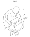
- FIG. 7 illustrates the manner in which a worker puts his or her arms into gaps between an outer surface of a contained object and side walls of the storage box according to the third exemplary embodiment, and grabs handhold portions.
- FIG. 1 illustrates a storage box 1 according to a first exemplary embodiment of the present invention.
- the storage box 1 illustrated in FIG. 1 is a rectangular parallelepiped shaped box made of corrugated paperboard, and includes a box body 10 , a pair of first lid walls 20 , and a pair of second lid walls 30 .
- the box body 10 includes a rectangular bottom wall 11 and four side walls 12 that stand upright at respective sides of the bottom wall 11 , and has an opening 10 a at the top.
- An object T to be contained in the storage box 1 is put into and taken out of the storage box 1 through the opening 10 a .
- the object T to be contained has a pair of handhold portions, which will be described below, that are located so as to face respective side walls 12 a that oppose each other, one of the side walls 12 a being at the near left side in FIG. 2 and the other side wall 12 a being at the far right side in FIG. 2 .
- a worker grabs the handhold portions when putting the object T into the storage box 1 or taking it out of the storage box 1 .
- the box body 10 corresponds to an example of a box body according to an exemplary embodiment of the present invention.
- the bottom wall 11 corresponds to an example of a bottom wall according to an exemplary embodiment of the present invention.
- the pair of side walls 12 a corresponds to an example of a pair of side walls according to an exemplary embodiment of the present invention.
- the pair of first lid walls 20 corresponds to an example of a pair of lid walls according to an exemplary embodiment of the present invention.
- the first lid walls 20 extend upward from the top edges of the respective side walls 12 a such that the first lid walls 20 are bendable along the top edges of the side walls 12 a .
- the first lid walls 20 are bent in the directions of arrows A along the top edges of the side walls 12 a , thereby forming a lid that covers the opening 10 a together with second lid walls 30 described below.
- the second lid walls 30 extend from the top edges of a pair of side walls 12 b other than the pair of side walls 12 a such that the second lid walls 30 are bendable along the top edges of the side walls 12 b .
- the second lid walls 30 are bent in the directions of arrows B along the top edges of the side walls 12 b so as to cover the pair of first lid walls 20 in the above-described bent state from above, thereby forming a lid that covers the opening 10 a together with the first lid walls 20 .
- the first lid walls 20 and the second lid walls 30 are opened to expose the opening 10 a.
- the pair of first lid walls 20 and the pair of side walls 12 a connected to the respective first lid walls 20 are provided with lines 40 described below.
- the lines 40 correspond to an example of first lines according to an exemplary embodiment of the present invention.
- Each line 40 lies along a line connecting a position 20 a that is on the top edge of the corresponding first lid wall 20 and that is above the corresponding handhold portion when the first lid wall 20 is opened and raised while the object T is contained in the box body 10 , and a position 12 a — 1 that is on the corresponding side wall 12 a and that opposes the handhold portion.
- the line 40 lies along this line and extends partway to the bottom edge of the side wall 12 a .
- the line 40 includes a lid segment 41 on the first lid wall 20 and a side wall segment 42 on the side wall 12 a , and the lid segment 41 and the side wall segment 42 are a perforated line and a fold line, respectively.
- the side walls 12 a on which the lines 40 are provided, have opening portions 50 located below the bottom ends of the side wall segments 42 of the lines 40 .
- the opening portions 50 may be torn open along perforated lines to form holes in the side walls 12 a when force is applied thereto.
- the opening portions 50 are opened by pivoting them about the bottom edges of the side walls 12 a .
- the side wall segments 42 of the lines 40 extend to the opening portions 50 .
- the opening portions 50 correspond to an example of opening portions according to an exemplary embodiment of the present invention.
- FIG. 2 illustrates the storage box 1 in the state in which the first lid walls 20 are cut along the lid segments 41 of the lines 40 and the opening portions 50 are opened.
- the contained object T has handhold portions T 1 that are grabbed when the contained object T is taken out.
- the opening portions 50 are positioned so as to face the respective handhold portions T 1 . Therefore, when the opening portions 50 are opened, the holes 51 are formed in the side walls 12 a at positions corresponding to the handhold portions T 1 .
- the worker views the opening 10 a of the storage box 1 from above when taking out the contained object T. Light enters through the holes 51 formed at the positions corresponding to the handhold portions T 1 to illuminate the regions around the handhold portions T 1 , so that the worker may easily find the handhold portions T 1 .
- the object T is contained in the storage box 1 while packing members S made of styrene foam are provided between the inner surface of the storage box 1 and four bottom corners of the contained object T. Accordingly, a gap corresponding to the thickness of the packing members S is provided between the outer surface of the contained object T and the inner surface of the storage box 1 .
- the worker inserts his or her arms into the gaps between the sides of the contained object T on which the handhold portions T 1 are formed and the side walls 12 a of the storage box 1 .
- the thickness of the packing members S is smaller than the thickness of the arms of the worker, so that the gaps into which the worker inserts his or her arms are smaller than the thickness of the arms of the worker.
- FIG. 3 illustrates the manner in which the worker puts his or her arms into the gaps between the outer surface of the contained object T and the side walls 12 a of the storage box 1 , and grabs the handhold portions T 1 .
- the gaps that are provided between the side surfaces of the contained object T and the side walls 12 a of the storage box 1 and into which the worker inserts his or her arms to take out the contained object T are smaller than the thickness of the arms of the worker.
- the first lid walls 20 which are connected to the side walls 12 a of the storage box 1 , are cut along the lid segments 41 of the lines 40 (see FIG. 2 ) so that cuts are formed therein.
- the side wall segments 42 which are fold lines, of the lines 40 are provided on the side walls 12 a of the storage box 1 so as to extend to the holes 51 formed when the opening portions 50 are opened.
- the side walls 12 a of the storage box 1 are pushed from the inside by the arms and bent along the side wall segments 42 , which are fold lines, in the directions of arrows D.
- the side walls 12 a are bent outward toward the outside of the box body 10 .
- the holes 51 are deformed so as to facilitate the outward bending of the side walls 12 a .
- the cuts formed in the first lid walls 20 along the lid segments 41 widen in the directions of arrows E.
- the gaps that are provided between the side surfaces of the contained object T and the side walls 12 a of the storage box 1 and that were initially small as described above widen to provide spaces that allow the worker to insert his or her arms deep enough to grab the handhold portions T 1 .
- the worker inserts his or her arms deep into these spaces, grabs the handhold portions T 1 , and takes the contained object T out of the storage box 1 .
- the second exemplary embodiment differs from the above-described first exemplary embodiment in that side walls of a storage box corresponding to the side walls 12 a connected to the first lid walls 20 according to the first exemplary embodiment are provided with second lines, which will be described below.
- the difference between the second exemplary embodiment and the first exemplary embodiment will be mainly described.
- FIG. 4 illustrates a storage box 2 according to the second exemplary embodiment of the present invention.
- FIG. 4 components similar to those of the storage box 1 according to the first exemplary embodiment illustrated in FIG. 1 are denoted by the same reference numerals as those in FIG. 1 , and explanations thereof are omitted in the following description to avoid redundancy.
- FIG. 5 which will be referred to below.
- side wall segments 42 ′ of lines 40 ′ provided on side walls 12 a which are connected to respective first lid walls 20 , extend to positions above and separated from respective opening portions 50 .
- Two second lines 60 extend from the bottom end of each side wall segment 42 ′ to both ends of the bottom edge of the corresponding side wall 12 a .
- the second lines 60 are fold lines that extend from the bottom end of the side wall segment 42 ′ to both ends of the bottom edge of the side wall 12 a .
- the lines 40 ′ correspond to an example of first lines according to an exemplary embodiment of the present invention.
- the second lines 60 correspond to an example of second lines according to an exemplary embodiment of the present invention.
- FIG. 5 illustrates the manner in which a worker puts his or her arms into gaps between an outer surface of a contained object T and the side walls 12 a of the storage box 2 according to the second exemplary embodiment, and grabs handhold portions T 1 .
- the side walls 12 a are pushed from the inside and outwardly bent in the directions of arrows D along the side wall segments 42 ′ of the lines 40 ′.
- the side walls 12 a are also outwardly bent along the second lines 60 , so that the second lines 60 facilitate the outward bending of the side walls 12 a along the side wall segment 42 ′.
- the side walls 12 a may be more easily bent outward compared to the case in which the second lines 60 are not provided on the side walls 12 a of the storage box 2 .
- segments of lines on lid walls that correspond to the first lid walls 20 according to the above-described first exemplary embodiment differ from the lid segments 41 of the lines 40 according to the first exemplary embodiment.
- the difference between the third exemplary embodiment and the first exemplary embodiment will be mainly described.
- FIG. 6 illustrates a storage box 3 according to the third exemplary embodiment of the present invention.
- FIG. 6 components similar to those of the storage box 1 according to the first exemplary embodiment illustrated in FIG. 1 are denoted by the same reference numerals as those in FIG. 1 , and explanations thereof are omitted in the following description to avoid redundancy.
- FIG. 7 which will be referred to below.
- lid segments 41 ′ of lines 40 ′′ on first lid walls 20 are fold lines.
- the lines 40 ′′ correspond to an example of first lines according to an exemplary embodiment of the present invention.
- a worker takes out an object T contained in the storage box 3 through an opening 10 a by inserting his or her arms into gaps between the outer surface of the contained object T and side walls 12 a of the storage box 3 and grabbing handhold portions.
- the worker grabs the handhold portions and takes out the contained object T while the pair of first lid walls 20 are raised, as described below.
- FIG. 7 illustrates the manner in which the worker puts his or her arms into the gaps between the outer surface of the contained object T and the side walls 12 a of the storage box 3 according to the third exemplary embodiment, and grabs the handhold portions.
- the worker inserts his or her arms into the gaps between the outer surface of the contained object T and the side walls 12 a of the storage box 3 while the pair of first lid walls 20 are raised.
- the first lid walls 20 are outwardly bent in the directions of arrows D together with the side walls 12 a along the lid segments 41 ′ of the lines 40 ′′.
- the gaps between the side surfaces of the contained object T and the side walls 12 a of the storage box 3 widen to provide spaces that allow the worker to insert his or her arms deep enough to grab the handhold portions.
- storage boxes including lid walls on which perforated lines or fold lines are formed as lines are described as storage boxes according to exemplary embodiments of the present invention.
- storage boxes according to exemplary embodiments of the present invention are not limited to this, and may instead include lid walls having cut lines as lines.
- storage boxes including side walls having opening portions that are located below the bottom ends of the lines and that may be torn open along perforated lines to form holes in the side walls when force is applied thereto are described as storage boxes according to exemplary embodiments of the present invention.
- storage boxes according to exemplary embodiments of the present invention are not limited to this, and may instead include side walls in which holes are initially formed.
- a storage box according to an exemplary embodiment of the present invention may instead be formed such that no holes or opening portions are provided.
- storage boxes in which the lines on the side walls extend partway to the bottom edges of the side walls and the opening portions are formed below the bottom ends of the lines are described as storage boxes according to exemplary embodiment of the present invention.
- storage boxes according to exemplary embodiments of the present invention are not limited to this, and may instead be formed such that no holes or opening portions are provided on the side walls and the lines extend to the bottom edges of the side walls.
- corrugated paperboard boxes are described as storage boxes according to exemplary embodiments of the present invention.
- storage boxes according to exemplary embodiments of the present invention are not limited to this, and may instead be, for example, a box made of paper other than corrugated paperboard or a box made of a plastic plate that is thin enough to be outwardly bent as described above.
- a storage box according to an exemplary embodiment of the present invention may be a box having a polygonal prism shape, other than a rectangular parallelepiped shape, having a pair of side walls that oppose each other.
- a storage box according to an exemplary embodiment of the present invention may have an octangular prism shape obtained by chamfering four corners of the rectangular bottom wall of the rectangular parallelepiped shape.
- Storage boxes according to exemplary embodiments of the present invention are also not limited to polygonal prism shaped boxes as long as the storage boxes include a pair of side walls that oppose each other.
- a storage box according to an exemplary embodiment of the present invention may be a box in which side walls other than a pair of side walls are curved.
Landscapes
- Engineering & Computer Science (AREA)
- Mechanical Engineering (AREA)
- Cartons (AREA)
- Closures For Containers (AREA)
- Details Of Rigid Or Semi-Rigid Containers (AREA)
Abstract
Description
Claims (4)
Applications Claiming Priority (2)
| Application Number | Priority Date | Filing Date | Title |
|---|---|---|---|
| JP2012-243500 | 2012-11-05 | ||
| JP2012243500A JP2014091558A (en) | 2012-11-05 | 2012-11-05 | Storage box |
Publications (2)
| Publication Number | Publication Date |
|---|---|
| US20140124515A1 US20140124515A1 (en) | 2014-05-08 |
| US8893919B2 true US8893919B2 (en) | 2014-11-25 |
Family
ID=50621423
Family Applications (1)
| Application Number | Title | Priority Date | Filing Date |
|---|---|---|---|
| US13/935,789 Active US8893919B2 (en) | 2012-11-05 | 2013-07-05 | Storage box |
Country Status (3)
| Country | Link |
|---|---|
| US (1) | US8893919B2 (en) |
| JP (1) | JP2014091558A (en) |
| CN (1) | CN103803149B (en) |
Cited By (1)
| Publication number | Priority date | Publication date | Assignee | Title |
|---|---|---|---|---|
| US20170369199A1 (en) * | 2016-06-28 | 2017-12-28 | David L. Dierberger | Tiered pizza tray support and pizza ingredient catch device |
Families Citing this family (4)
| Publication number | Priority date | Publication date | Assignee | Title |
|---|---|---|---|---|
| CN111453129B (en) * | 2020-05-21 | 2024-08-13 | 天津博容包装制品有限公司 | Packaging box convenient for packaging and manufacturing method thereof |
| US12145775B2 (en) | 2022-03-23 | 2024-11-19 | Hebei Fenger Intelligent Technology Co., Ltd. | Storage box cover and storage box used therewith |
| US11772854B2 (en) | 2022-03-23 | 2023-10-03 | Genicook Product Llc | Storage box |
| CN115771664B (en) * | 2022-12-24 | 2024-05-24 | 安徽新隆泰包装股份有限公司 | Packing box |
Citations (8)
| Publication number | Priority date | Publication date | Assignee | Title |
|---|---|---|---|---|
| US5141149A (en) * | 1991-08-05 | 1992-08-25 | Fulton J Scott | Multiple use plant shipping and display container |
| US5318219A (en) * | 1992-06-05 | 1994-06-07 | Four M Manufacturing Group Of Cpc, Inc. | Collapsible pallet mounted container |
| US5474230A (en) * | 1992-10-16 | 1995-12-12 | Hitachi Kasei Shoji Co., Ltd. | Folding box |
| US6050410A (en) * | 1998-01-11 | 2000-04-18 | Quirion; M. Yvan | Foldable pallet-mounted container |
| US20050087590A1 (en) * | 2003-01-28 | 2005-04-28 | Masahiro Kawagoe | Packaging container and method for folding up the same |
| JP2005239222A (en) | 2004-02-26 | 2005-09-08 | Japan Storage Battery Co Ltd | Packing box |
| US20120000912A1 (en) * | 2010-06-30 | 2012-01-05 | Prolound Products, Inc. | Organizer container for vehicle trunk or other use |
| US20140048546A1 (en) * | 2012-08-16 | 2014-02-20 | Bigbagbox International, Inc. | Collapsible Container |
Family Cites Families (2)
| Publication number | Priority date | Publication date | Assignee | Title |
|---|---|---|---|---|
| JP2010241434A (en) * | 2009-04-01 | 2010-10-28 | Starway Co Ltd | Article storage box |
| CN201545251U (en) * | 2009-11-17 | 2010-08-11 | 上海鹈鸬国际贸易有限公司 | Carton convenient for folding and unfolding and providing sealing function |
-
2012
- 2012-11-05 JP JP2012243500A patent/JP2014091558A/en active Pending
-
2013
- 2013-07-05 US US13/935,789 patent/US8893919B2/en active Active
- 2013-08-09 CN CN201310346732.1A patent/CN103803149B/en active Active
Patent Citations (8)
| Publication number | Priority date | Publication date | Assignee | Title |
|---|---|---|---|---|
| US5141149A (en) * | 1991-08-05 | 1992-08-25 | Fulton J Scott | Multiple use plant shipping and display container |
| US5318219A (en) * | 1992-06-05 | 1994-06-07 | Four M Manufacturing Group Of Cpc, Inc. | Collapsible pallet mounted container |
| US5474230A (en) * | 1992-10-16 | 1995-12-12 | Hitachi Kasei Shoji Co., Ltd. | Folding box |
| US6050410A (en) * | 1998-01-11 | 2000-04-18 | Quirion; M. Yvan | Foldable pallet-mounted container |
| US20050087590A1 (en) * | 2003-01-28 | 2005-04-28 | Masahiro Kawagoe | Packaging container and method for folding up the same |
| JP2005239222A (en) | 2004-02-26 | 2005-09-08 | Japan Storage Battery Co Ltd | Packing box |
| US20120000912A1 (en) * | 2010-06-30 | 2012-01-05 | Prolound Products, Inc. | Organizer container for vehicle trunk or other use |
| US20140048546A1 (en) * | 2012-08-16 | 2014-02-20 | Bigbagbox International, Inc. | Collapsible Container |
Cited By (1)
| Publication number | Priority date | Publication date | Assignee | Title |
|---|---|---|---|---|
| US20170369199A1 (en) * | 2016-06-28 | 2017-12-28 | David L. Dierberger | Tiered pizza tray support and pizza ingredient catch device |
Also Published As
| Publication number | Publication date |
|---|---|
| CN103803149B (en) | 2018-06-22 |
| JP2014091558A (en) | 2014-05-19 |
| US20140124515A1 (en) | 2014-05-08 |
| CN103803149A (en) | 2014-05-21 |
Similar Documents
| Publication | Publication Date | Title |
|---|---|---|
| US20140124515A1 (en) | Storage box | |
| JP2020533247A5 (en) | ||
| JP5961616B2 (en) | Smoking pack | |
| JP7107098B2 (en) | packaging box | |
| JP2006021808A (en) | Tray-like box for packaging | |
| US10023351B2 (en) | Box and package | |
| JP5545730B2 (en) | Ruled line structure and packaging box for paper products | |
| EP2436614A1 (en) | Collapsible container | |
| JP5685038B2 (en) | Household tissue paper storage box | |
| KR200456896Y1 (en) | Paper box | |
| JP6637453B2 (en) | Packaging box | |
| JP2006264717A (en) | Plastic container | |
| JP6259788B2 (en) | Packing box | |
| JP6363364B2 (en) | Tissue paper storage container | |
| JP4981520B2 (en) | Container storage structure | |
| US20140346083A1 (en) | Container for packaging paper sheets, and paper sheet package body | |
| JP6776990B2 (en) | Packaging boxes and blank sheets for packaging boxes | |
| JP2007022580A (en) | Box type container | |
| JP6780951B2 (en) | Packaging box | |
| JP6998007B2 (en) | Cover structure and packaging container using this | |
| KR102682226B1 (en) | Packaging box packed without using tape by using wings of different size | |
| JP2020164211A (en) | Packing box | |
| CN110104300B (en) | Packaging box, using method of packaging box and manufacturing method of packaging box | |
| JP2009241948A (en) | Inner box | |
| JP2012201398A (en) | Corrugated cardboard for assembling box and corrugated box |
Legal Events
| Date | Code | Title | Description |
|---|---|---|---|
| AS | Assignment |
Owner name: FUJI XEROX CO., LTD., JAPAN Free format text: ASSIGNMENT OF ASSIGNORS INTEREST;ASSIGNORS:KABE, YUSUKE;YOSHIDA, TAKAAKI;REEL/FRAME:030839/0495 Effective date: 20130328 |
|
| STCF | Information on status: patent grant |
Free format text: PATENTED CASE |
|
| MAFP | Maintenance fee payment |
Free format text: PAYMENT OF MAINTENANCE FEE, 4TH YEAR, LARGE ENTITY (ORIGINAL EVENT CODE: M1551) Year of fee payment: 4 |
|
| AS | Assignment |
Owner name: FUJIFILM BUSINESS INNOVATION CORP., JAPAN Free format text: CHANGE OF NAME;ASSIGNOR:FUJI XEROX CO., LTD.;REEL/FRAME:058287/0056 Effective date: 20210401 |
|
| MAFP | Maintenance fee payment |
Free format text: PAYMENT OF MAINTENANCE FEE, 8TH YEAR, LARGE ENTITY (ORIGINAL EVENT CODE: M1552); ENTITY STATUS OF PATENT OWNER: LARGE ENTITY Year of fee payment: 8 |
|
| MAFP | Maintenance fee payment |
Free format text: PAYMENT OF MAINTENANCE FEE, 12TH YEAR, LARGE ENTITY (ORIGINAL EVENT CODE: M1553); ENTITY STATUS OF PATENT OWNER: LARGE ENTITY Year of fee payment: 12 |