US8890728B2 - Method and device for use with analog to digital converter - Google Patents
Method and device for use with analog to digital converter Download PDFInfo
- Publication number
- US8890728B2 US8890728B2 US14/179,993 US201414179993A US8890728B2 US 8890728 B2 US8890728 B2 US 8890728B2 US 201414179993 A US201414179993 A US 201414179993A US 8890728 B2 US8890728 B2 US 8890728B2
- Authority
- US
- United States
- Prior art keywords
- matrix
- processing
- samples
- train
- correlation
- Prior art date
- Legal status (The legal status is an assumption and is not a legal conclusion. Google has not performed a legal analysis and makes no representation as to the accuracy of the status listed.)
- Active
Links
Images


Classifications
-
- H—ELECTRICITY
- H03—ELECTRONIC CIRCUITRY
- H03M—CODING; DECODING; CODE CONVERSION IN GENERAL
- H03M1/00—Analogue/digital conversion; Digital/analogue conversion
- H03M1/06—Continuously compensating for, or preventing, undesired influence of physical parameters
- H03M1/0617—Continuously compensating for, or preventing, undesired influence of physical parameters characterised by the use of methods or means not specific to a particular type of detrimental influence
- H03M1/0624—Continuously compensating for, or preventing, undesired influence of physical parameters characterised by the use of methods or means not specific to a particular type of detrimental influence by synchronisation
-
- H—ELECTRICITY
- H03—ELECTRONIC CIRCUITRY
- H03M—CODING; DECODING; CODE CONVERSION IN GENERAL
- H03M1/00—Analogue/digital conversion; Digital/analogue conversion
-
- H—ELECTRICITY
- H03—ELECTRONIC CIRCUITRY
- H03M—CODING; DECODING; CODE CONVERSION IN GENERAL
- H03M1/00—Analogue/digital conversion; Digital/analogue conversion
- H03M1/12—Analogue/digital converters
-
- H—ELECTRICITY
- H03—ELECTRONIC CIRCUITRY
- H03M—CODING; DECODING; CODE CONVERSION IN GENERAL
- H03M1/00—Analogue/digital conversion; Digital/analogue conversion
- H03M1/12—Analogue/digital converters
- H03M1/1205—Multiplexed conversion systems
- H03M1/121—Interleaved, i.e. using multiple converters or converter parts for one channel
- H03M1/1215—Interleaved, i.e. using multiple converters or converter parts for one channel using time-division multiplexing
-
- H—ELECTRICITY
- H03—ELECTRONIC CIRCUITRY
- H03M—CODING; DECODING; CODE CONVERSION IN GENERAL
- H03M1/00—Analogue/digital conversion; Digital/analogue conversion
- H03M1/12—Analogue/digital converters
- H03M1/1205—Multiplexed conversion systems
- H03M1/122—Shared using a single converter or a part thereof for multiple channels, e.g. a residue amplifier for multiple stages
- H03M1/1225—Shared using a single converter or a part thereof for multiple channels, e.g. a residue amplifier for multiple stages using time-division multiplexing
Definitions
- the present invention relates generally to electronics circuits and methods, and, in particular embodiments, to a method and device for compensating the timing skew mismatch of several time interleaved analog to digital converters.
- Certain applications require analog/digital converters exhibiting a high sampling frequency and high resolution.
- these applications are cable TV transmissions, optical communications, and satellite communications in which one or more modulated signals are transmitted simultaneously on a wide frequency band (for example several GHz wide).
- TIADCs Time-Interleaved Analog-to-Digital Converters
- TIADCs Time-Interleaved Analog-to-Digital Converters
- the temporally interleaved analog/digital converters respectively perform temporally shifted analog/digital conversions of an analog signal.
- the structure comprises M converters, the latter successively sample each in their turn the signal at a frequency equal to Fs/M, where Fs is the global frequency of sampling of the structure.
- Timing skew clock shifts
- offset gains and/or shifts
- a mismatch in terms of clock shift or gain adds to the frequency spectrum of the output signal attenuated spurious images of the frequency spectrum of the input signal around the frequencies that are multiples of Fs/M.
- offset A mismatch in terms of shift (“offset”) creates spurious spectral lines localized at frequencies that are multiples of Fs/M. Furthermore these shifts can vary over time.
- Embodiments of the invention relate to the processing of a sampled signal, for example, to the correction of this sampled signal so as in particular to correct the disparity of the clock shifts (known by the expression “timing skew mismatch”) of several analog/digital converters of an analog/digital conversion system delivering this sampled signal.
- Embodiments of the invention apply in particular but not exclusively to the correction of the mismatch between the various values of the clock shifts of several analog/digital converters said to be “temporally interleaved”, that is to say performing respectively temporally shifted analog/digital conversions of an analog signal so as to increase the global sampling frequency.
- a method and a device for processing a sampled signal arising from a structure of temporally interleaved converters making it possible to estimate the mismatch in terms of clock shifts of the converters, in particular in a simple and fast manner, without requiring a feedback loop or a calibration phase.
- a method and a processing device also making it possible to estimate the shift value (“offset”) of each analog/digital converter of the structure, to correct the values of the samples so as to take account of this estimated shift value in terms of voltage, and therefore to compensate the mismatch of these shifts, while spreading over the whole of the frequency spectrum, the residual frequency spectral lines resulting from the quantization of the corrected signal.
- a method for processing a sampled signal comprising M, M being greater than two, original trains of original samples respectively arising from M temporally interleaved converters, that is to say respectively performing temporally shifted analog/digital conversions of an analog signal.
- the original trains of samples can be the trains of samples actually delivered as output from the converters, or else, if the trains delivered by the converters have undergone a prior processing, for example a compensation “of offset” and/or a compensation in terms of gain, trains arising from these trains delivered by the converters, for example the trains preprocessed by the compensation of offset and/or in terms of gain.
- the method according to this aspect comprises a first processing comprising a selection of an original train in the guise of reference train, and for the M ⁇ 1 other original trains, at least one estimation of a suite of M ⁇ 1 shift coefficients respectively representative of clock shifts between these M ⁇ 1 other original trains and the reference train.
- the at least one estimation comprises on the one hand a correlation processing involving at least one part of the sampled signal, at least one part of at least one first signal gleaned from a sampled derived signal representative of a temporal derivative of the input signal and at least one part of N partial filtered signals respectively representative of N weighted differences between N pairs of bracketing versions flanking the sampled signal, N being greater than or equal to 1.
- a pair of bracketing versions flanking the sampled signal comprises a version comprising, for each current sample of the signal, a K th sample following this current sample and a version of the signal comprising, for each current sample, a K th sample preceding this current sample.
- the parts of the sampled signal, of the at least one first signal and of the filtered partial signal or signals on which the at least one correlation processing is performed can each comprise a group of L samples, for example a million samples, of the corresponding signal.
- each correlation of the correlation processing can comprise an average of L products of samples.
- This average can be a conventional average or any other type of average, for example a weighted average or else a modified moving average (MMA) of period L samples.
- MMA modified moving average
- N can be equal to 1.
- N can be equal to 1.
- N only a single pair of bracketing versions flanking the sampled signal is used, for example the two neighboring samples bracketing a current sample. That said, using several pairs of bracketing versions (N greater than 1) makes it possible to estimate the clock shifts (timing skew) by weighting the various useful frequency zones of the signal differently.
- N When N is greater than 1, N can be less than, equal to or greater than M.
- the at least one estimation comprises on the other hand a matrix processing on the results of the correlation processing.
- the method according to this aspect thus makes it possible to perform the estimation of the clock shifts of the converters in a forward (“direct”) manner, that is to say without feedback correction of the original samples on the basis of information situated downstream of the point of reception of the original samples to be processed (corrected).
- This therefore requires just a single iteration, that is to say no feedback loop without risk of divergence nor necessity to provide a calibration phase. Therefore the hardware embodiment thereof is simplified and the estimation of the mismatch faster.
- the compensation in terms of clock shifts advantageously comprises a correction of the sampled signal with the estimated shift coefficients.
- the first processing also comprises at least one processing for correcting the M ⁇ 1 other original trains involving respectively M ⁇ 1 second signals gleaned from the derived signal and the suite of M ⁇ 1 estimated shift coefficients, so as to deliver M processed trains including the reference original train and M ⁇ 1 corrected original trains.
- the M ⁇ 1 second signals thus comprise for example respectively the samples of the derived signal that are respectively associated with the M ⁇ 1 other original trains.
- the at least one correction processing can comprise a first-order Taylor approximation.
- Such a correction processing performed on the sampled signal makes it possible to compensate the mismatch in terms of clock shifts at the tempo of arrival of the samples to be corrected.
- the correlation processing comprises at least one set of N first correlations between the at least one part of the at least one first signal and at least one part of N third signals respectively gleaned from the N partial filtered signals, delivering at least one set of N first results of correlations.
- the N third signals advantageously comprise the samples of the N partial filtered signals associated with a single original train, for example the hereinabove mentioned said one of the M original trains (that is to say the original train associated with the first signal), and the correlation processing then comprises a single set of N first correlations between the at least one part of the first signal and the at least one part of the N third signals, delivering a single set of N first results of correlations.
- the parts of the third signals comprise for example L samples.
- the at least one estimation comprises a calculation of a global filtered signal resulting from the sum of the N partial filtered signals
- the correlation processing comprises M second correlations between respectively the samples of the M original trains and the corresponding samples of the global filtered signal, delivering M second correlation results.
- the correlation processing delivers at least one set of N first correlation results and a set of M second correlation results and the matrix processing comprises a calculation of a final matrix of size (M ⁇ 1) ⁇ M (M ⁇ 1 rows and M columns) on the basis of at least one first constant circulant matrix and of the first correlation results and a multiplication of the M second correlation results with the coefficients of the final matrix, so as to obtain the suite of M ⁇ 1 shift coefficients.
- the calculation of the final matrix advantageously comprises a calculation of an intermediate matrix on the basis of a single first constant circulant matrix, a calculation of a pseudo-inverse matrix of the intermediate matrix and a weighting of the coefficients of the pseudo-inverse matrix with the first correlation result, for example its inverse, so as to obtain the coefficients of the final matrix.
- the first constant circulant matrix is for example a matrix of size M ⁇ M whose coefficients are equal
- the intermediate matrix is the first constant circulant matrix ridded of its first column, and the weighting of the coefficients of the pseudo inverse matrix comprises a division of these coefficients by the first correlation result so as to obtain the coefficients of the final matrix.
- the calculation of the final matrix advantageously comprises a calculation of an intermediate matrix on the basis of a linear combination of N second constant circulant matrices respectively arising from N first constant circulant matrices, the combination being weighted by the N first correlation results, and a calculation of a pseudo-inverse matrix of the intermediate matrix, this pseudo-inverse matrix forming the final matrix.
- Each first constant circulant matrix of rank i, with i varying from 1 to N, is then for example a matrix of size M ⁇ M
- each second circulant matrix is then the first circulant matrix ridded of its first column.
- the first processing can comprise several successive estimations so as to deliver several successive suites of M ⁇ 1 shift coefficients, and if appropriate several digital processings of successive corrections successively using the estimated successive suites of M ⁇ 1 shift coefficients. This makes it possible in particular to take account of a temperature modification.
- the method can advantageously comprise, before or after the first processing, a second processing comprising, after a transient phase, an equalization of the mean powers of the various initial trains of initial samples performed on the fly and at the tempo of delivery of the samples, on the basis of the values of initial samples of these initial trains, so as to deliver processed trains of processed samples;
- an initial train can be a train delivered by the corresponding converter or else a train arising from this converter having undergone a preprocessing, for example an offset compensation, or else a train processed by the first processing (compensation of clock shifts).
- the transient phase corresponds for example to the number of current samples required to obtain an accuracy deemed acceptable, for the envisaged application, in the values of the mean powers.
- This transient period can be longer or shorter as a function of the way in which the mean power is determined.
- each mean power can comprise the use of a modified moving average.
- a modified moving average of period L samples which is computed for example on the basis of a group of values of samples containing the current sample and a plurality of preceding samples of the corresponding train, is particularly advantageous since it allows frequent updating of the estimated value of the mean power and it allows in particular temporal tracking of the changes due to temperature for example.
- a modified moving average although having a period of L samples, is in practice always computed over a very large number of samples and the estimated value then has an acceptable accuracy after a duration corresponding to several periods of L samples.
- Equalization of the mean powers makes it possible to perform a compensation of the mismatch in terms of gain of the converters. Moreover this equalization is performed on the fly and at the tempo of delivery of the initial samples. Stated otherwise it is performed in a forward (“direct”) manner, that is to say without feedback correction of the initial samples on the basis of information situated downstream of the point of reception of the initial samples to be processed (corrected). Therefore the hardware embodiment thereof is simplified and the compensation of the mismatch faster.
- the equalization of the mean powers of the various initial trains of samples comprises a selection of one of the initial trains as reference initial train and, for each of the other initial trains, an estimation of the relative gain between the corresponding converter and the converter delivering the reference initial train, and a correction of the values of the initial samples of each of the other initial trains by the corresponding relative gain so as to deliver the corresponding processed samples, the estimation and the correction being performed on the fly and at the tempo of delivery of the initial samples.
- mean power is advantageously considered in a very broad sense encompassing not only the effective mean power but also any variable representative of this mean power, such as for example an average of absolute values.
- the estimation of the relative gain between each other converter and the converter delivering the reference initial train comprises a determination of an average, for example a modified moving average, of the absolute values of samples of the reference initial train, and, for the other initial train, a determination of an average, for example a modified moving average, of the absolute values of samples of this other initial train, and a ratio of these two averages.
- the ratio is representative of the relative gain.
- the correction of the values of the initial samples of each of the other initial trains by the corresponding relative gain comprises for example a division of the values of the initial samples by the estimated relative gain.
- a modified moving average of period L samples computed for example on the basis of a group of values of initial samples containing the current initial sample and a plurality of preceding initial samples of the corresponding initial train, is particularly advantageous since, as indicated hereinabove, it allows frequent updating of the estimated value of the power and therefore of the relative gain and it allows in particular temporal tracking of the changes due to temperature for example.
- the method can comprise furthermore, before or after the first processing, and if appropriate before or after the second processing, a third processing comprising, after a transient period (which can be identical or different from that relating to the equalization of the mean powers), for each current primary sample of each primary train arising from the corresponding converter,
- a primary train of primary samples can be a train of samples actually delivered by the corresponding converter, if this “offset” compensation is performed before the compensation in terms of gain, or else a processed train of processed samples if this offset compensation is performed after the gain compensation processing or after the clock shifts compensation processing.
- transient phase corresponds for example to the number of current samples required to obtain an accuracy deemed acceptable, for the envisaged application, in the estimated value of the shift which will correspond to the average of the values of the pseudo-random sequence of digital words.
- This transient period can be longer or shorter as a function of the way in which this mean value is estimated.
- the estimation of the value of the voltage offset of the corresponding converter can comprise a modified moving average of the values of primary samples arising from this converter.
- the corrected current sample and the current primary sample arising from the converter can be coded on one and the same number of bits.
- the current intermediate sample can be identical to the current primary sample.
- the corrected current sample can advantageously be coded on a larger number of bits than that of the current primary sample arising from the corresponding converter.
- the current intermediate sample can be the current primary sample supplemented with an appropriate number of low-order bits equal to 0.
- the mean value of the primary samples arising from the corresponding converter is “continually” equalized to a constant reference value, in practice a zero or almost zero value.
- the estimated shift of the corresponding converter is therefore taken into account to perform a corresponding correction at the level of each sample.
- a particularly simple way of achieving the pseudo-random sequence having as average the estimated value of the shift consists in calculating an initial pseudo-random sequence of zero or almost zero average and to sum over each word delivered by this initial sequence the estimated value of the shift.
- the corrected samples of each train are coded on n bits and the calculation of the digital correction word comprises
- the value of “the offset” of the corresponding converter is determined on a greater number of bits than that of the primary samples arising from the converter, thereby making it possible to estimate the decimal part of “the offset”.
- This decimal part is corrected by b-n bits, for example the b-n low-order bits, of the initial digital word arising from the initial pseudo-random sequence, and the digital correction word is therefore the integer part of the estimated value of the offset, which is either unchanged, or incremented by 1 or decremented by 1 as a function of the values of the b-n bits of the initial digital word that are used for the correction.
- the determination of the digital correction word comprises
- a calculation of a modified digital word comprising the b-n bits of the initial digital word, supplemented with n high-order bits all having the same logic value (for example the logic value 0 or the logic value 1), and
- the digital correction word being formed by the n high-order bits of the word of b bits resulting from the summation.
- An input device receives a sampled signal comprising M original trains of liminary samples respectively arising from M analog/digital converters with temporal interleaving.
- M is greater than two and one of the original trains is considered to be the reference train.
- a first processing module comprises an estimation unit configured to perform for the M ⁇ 1 other original trains, at least one estimation of a suite of M ⁇ 1 shift coefficients respectively representative of clock shifts between these M ⁇ 1 other original trains and the reference train.
- the estimation unit comprises, on the one hand, a correlation unit configured to perform a correlation processing involving at least one part of the sampled signal.
- At least one part of at least one first signal is gleaned from a derived signal representative of a temporal derivative of the sampled signal and at least one part of N partial filtered signals respectively representative of N weighted differences between N pairs of bracketing versions flank the sampled signal.
- N is greater than or equal to 1.
- the estimation unit comprises, on the other hand, a matrix processing unit configured to perform a matrix processing on the results of this correlation processing.
- the first processing module comprises a correction unit configured to perform at least one processing for correcting the M ⁇ 1 other trains involving respectively M ⁇ 1 second signals gleaned from the derived signal and the suite of M ⁇ 1 shift coefficients, so as to deliver M processed trains including the reference original train and M ⁇ 1 corrected original trains.
- the correction unit can be configured to perform a first-order Taylor approximation.
- the parts of the sampled signal, of the at least one first signal and of the filtered partial signal or signals on which the at least one correlation processing is performed each comprise a group of L samples of the corresponding signal.
- the first signal can moreover comprise the samples of the derived signal that are associated with one of the M trains and the M ⁇ 1 second signals can comprise respectively the samples of the derived signal that are respectively associated with the M ⁇ 1 other trains.
- the correlation unit is configured to perform at least one set of N first correlations between the at least one part of the at least one first signal and at least one part of N third signals respectively gleaned from the N partial filtered signals, delivering at least one set of N first results of correlations.
- the N third signals comprise the samples of the N partial filtered signals associated with the one of the M trains
- the correlation unit is configured to perform a single set of N first correlations between the at least one part of the first signal and the at least one part of the N third signals, delivering a single set of N first results of correlations.
- the parts of the third signals can also comprise L samples.
- the estimation unit is furthermore configured to calculate a global filtered signal resulting from the sum of the N partial filtered signals
- the correlation unit is configured to perform M second correlations between respectively the samples of the M original trains and the corresponding samples of the global filtered signal, delivering M second correlation results.
- the correlation unit can be configured to perform each correlation by using an average of L products of samples.
- the correlation unit is configured to deliver at least one set of N first correlation results and a set of M second correlation results and the matrix processing unit is configured to calculate a final matrix of size (M ⁇ 1) ⁇ M on the basis of at least one first constant circulant matrix and of the first correlation results and to perform a multiplication of the M second correlation results with the coefficients of the final matrix, so as to obtain the suite of M ⁇ 1 shift coefficients.
- N is equal to 1 and the correlation unit is configured to deliver a single first correlation result obtained on the basis of the train arising from a single converter, and the matrix processing unit is configured to calculate an intermediate matrix on the basis of a single first constant circulant matrix, a pseudo-inverse matrix of the intermediate matrix and to perform a weighting of the coefficients of the pseudo-inverse matrix with the first correlation result so as to obtain the coefficients of the final matrix.
- the first constant circulant matrix is then for example a matrix of size M ⁇ M whose coefficients are equal to 1 when the row index is equal to the column index, to ⁇ 0.5 if the column index is equal to the row index plus or minus 1 modulo M and to 0 otherwise, the intermediate matrix is the first constant circulant matrix ridded of its first column, and the matrix processing unit is configured to perform a division of these coefficients by the first correlation result so as to obtain the coefficients of the final matrix.
- N is greater than 1 and the correlation unit is configured to deliver N first results obtained on the basis of the train arising from a single converter, and the matrix processing unit is configured to calculate an intermediate matrix on the basis of a linear combination of N second constant circulant matrices respectively arising from N first constant circulant matrices, the combination being weighted by the N first correlation results, and a pseudo-inverse matrix of the intermediate matrix, this pseudo-inverse matrix forming the final matrix.
- Each first constant circulant matrix of rank i, with i varying from 1 to N, is then for example a matrix of size M ⁇ M
- each second circulant matrix being the first circulant matrix ridded of its first column.
- the estimation unit is configured to perform several successive estimations so as to deliver several successive suites of M ⁇ 1 shift coefficients
- the correction unit is configured to perform several successive processings of corrections successively using the estimated successive suites of M ⁇ 1 shift coefficients.
- the device furthermore comprises a second processing module configured to perform before or after the first processing, a second processing comprising, after a transient phase, an equalization of the mean powers of the various initial trains of initial samples performed on the fly and at the tempo of delivery of the samples, on the basis of the values of initial samples of these initial trains, so as to deliver processed trains of processed samples, an initial train being able to be a train arising from the corresponding converter or else a processed train delivered by the first processing module.
- a second processing module configured to perform before or after the first processing, a second processing comprising, after a transient phase, an equalization of the mean powers of the various initial trains of initial samples performed on the fly and at the tempo of delivery of the samples, on the basis of the values of initial samples of these initial trains, so as to deliver processed trains of processed samples, an initial train being able to be a train arising from the corresponding converter or else a processed train delivered by the first processing module.
- one of the initial trains is taken as reference initial train.
- the second processing module comprises a first block configured to perform on the fly and at the tempo of delivery of the initial samples, for each of the other initial trains, an estimation of the relative gain between the corresponding converter and the converter associated with the reference initial train.
- the second processing module also comprises a second block configured to perform on the fly and at the tempo of delivery of the initial samples, a correction of the values of the initial samples of each of the other initial trains by the corresponding relative gain.
- the first block comprises a number of circuits.
- a first circuit is configured to determine an average, for example a modified moving average, of the absolute values of initial samples of the reference initial train.
- Second circuits are respectively configured to determine for the other initial trains, the averages, for example modified moving averages, of the absolute values of initial samples of these other initial trains.
- Third circuits are respectively configured to determine ratios between the average of the absolute values of initial samples of the reference initial train and the averages of the absolute values of initial samples of the other initial trains, the ratios being representative of the relative gains.
- the second block comprises for example dividers respectively configured to divide values of the initial samples of the other initial trains by the corresponding estimated relative gains.
- the device furthermore comprises a third processing module configured to perform, before or after the first processing, and if appropriate before or after the second processing, a third processing.
- the third processing is performed, after a transient phase, for each current primary sample of each primary train arising from the corresponding converter.
- the processing includes a calculation of a digital correction word belonging to a pseudo-random sequence of digital words, the average of whose values is equal or almost equal to a value of the shift of the corresponding converter, estimated on the basis of the values of primary samples of the primary train arising from the corresponding converter.
- the processing also includes a subtraction of the digital correction word from a current intermediate sample obtained on the basis of this current primary sample so as to deliver a corrected current sample.
- a primary train can be a train delivered by the corresponding converter or a processed train delivered by the first or the second processing module.
- the third processing module comprises, for each primary train of primary samples, a first block configured to estimate the value of the shift of the corresponding converter, coded on b bits and associated with the current primary sample, b being greater than n.
- a second block is configured to determine the digital correction word coded on n bits on the basis of the estimated shift value coded on b bits that is delivered by the first block and of b-n bits of an initial digital word arising from a generator of an initial pseudo-random sequence of initial digital words whose values have a zero or almost zero average.
- the second block comprises, for example, a number of components including the generator of the initial pseudo-random sequence.
- a modification unit is configured to deliver a modified digital word comprising the b-n bits of the initial digital word, supplemented with n high-order bits all having the same logic value.
- a summation unit is configured to sum the modified digital word and the estimated shift value, the digital correction word being formed by the n high-order bits of the word of b bits that is delivered by the summation unit.
- the third processing module is configured to estimate the value of the voltage offset of the corresponding converter by a modified moving average of the values of the primary samples arising from this converter.
- an integrated circuit incorporating a processing device such as defined hereinabove.
- FIGS. 1 to 25 deal with various modes of implementation and embodiment of a method and of a processing device according to the invention.
- the reference SCV designates a system or structure for analog-digital conversion of an analog signal x(t).
- the analog-digital conversion system employs temporal interleaving comprising several temporally interleaved analog-digital converters (here M analog-digital converters) ADC 0 -ADC M ⁇ 1 .
- the analog-digital converter ADC m is driven by the clock signal clk m .
- the frequency of the clock signal clk m is equal to Fs/M where Fs denotes the effective frequency at which the analog signal x(t) is sampled. Fs can typically be equal to several GHz or several tens of GHz.
- the period of each clock signal clk m is equal to MTs where Ts denotes the period of the clock signal clk having Fs as frequency.
- the sampling of the analog signal x(t) is performed in parallel and in this FIG. 2 which illustrates a perfect theoretical case, each converter ADC m samples the same analog signal with a temporal shift equal to Ts with respect to the preceding converter.
- each converter ADC m delivers an original train of original samples ⁇ tilde over (x) ⁇ m [k].
- timing skew there may be a clock shift (“timing skew”) between the various clock signals clk m .
- each clock signal clk m is shifted temporally by a temporal shift ⁇ t m with respect to this reference clock signal.
- the temporal shifts ⁇ t m are small compared with the period Ts.
- r m
- r m here denotes a shift coefficient representative of the clock shift between the original train arising from the converter ADC m and the reference train, in this instance the train arising from the converter ADC 0 .
- the M analog/digital converters of the conversion system SCV do not generally have the same clock shift. This mismatch in terms of clock shift adds to the frequency spectrum of the output signal attenuated spurious images of the frequency spectrum of the input signal around the frequencies that are multiples of Fs/M.
- This processing method is implemented within a processing device DIS whose M input terminals BE 0 -BE M ⁇ 1 receive the M trains of samples ⁇ tilde over (x) ⁇ m [k], with m varying from 0 to M ⁇ 1.
- the device DIS comprises a first processing module MT 1 delivering as output processed trains of processed samples ⁇ circumflex over (x) ⁇ m [k], with m varying from 0 to M ⁇ 1.
- the first processing module MT 1 comprises estimation unit configured to perform, for the M ⁇ 1 original trains other than the reference original train, at least one estimation of a suite of M ⁇ 1 shift coefficients ⁇ circumflex over (r) ⁇ m (m varying from 1 to M ⁇ 1) respectively representative of the clock shifts between these M ⁇ 1 other original trains and the reference train.
- the coefficient ⁇ circumflex over (r) ⁇ 0 is taken equal to 0 since it entails the reference.
- the module MT 1 moreover comprises correction unit configured to perform at least one processing for correcting the M ⁇ 1 other trains by using in particular these M ⁇ 1 shift coefficients.
- FIGS. 4 to 9 illustrate a first simplified version for embodying the module MT 1 of the device DIS.
- the estimation unit MST is intended to estimate the M ⁇ 1 shift coefficients ⁇ circumflex over (r) ⁇ m , m varying from 1 to M ⁇ 1 ( ⁇ circumflex over (r) ⁇ 0 being taken here equal to 0) comprise a derivative filter FD, correlation unit here comprising two correlation blocks BCR 1 and BCR 2 , and matrix processing unit MTM.
- the correction unit MCR receive the samples ⁇ tilde over (x) ⁇ m [k] of the sampled signal, the derived signal x D [k] delivered by the derivative filter as well as the estimated shift coefficients ⁇ circumflex over (r) ⁇ m , m varying from 0 to M ⁇ 1.
- the samples are for example corrected with zero values.
- the estimation may be performed just once, the suite of coefficients ⁇ circumflex over (r) ⁇ m then remaining valid throughout the duration of operation of the device
- the estimation can be re-performed repeatedly (arrow 40 FIG. 4 ) so as to update the suite of shift coefficients ⁇ circumflex over (r) ⁇ m to take account in particular of alterations in operating temperature for example.
- the corrected samples ⁇ circumflex over (x) ⁇ m [k], with m varying from 0 to M ⁇ 1, are thereafter “reparallelized” in a demultiplexer DMUX so as to deliver M processed trains of processed samples ⁇ circumflex over (x) ⁇ m [k], with m varying from 0 to M ⁇ 1.
- the derivative filter FD is, as illustrated in FIG. 5 , a filter of conventional and known structure having K D coefficients d 1 -d KD , and comprising a set of flip-flops BSC to delay the signal and a set of “subtracter-multiplier” pairs.
- the filter FD thus receives the samples ⁇ tilde over (x) ⁇ [k] of the sampled signal and delivers as output the corresponding samples x D M of a derived signal representative of the temporal derivative of the sampled signal.
- This filter makes it possible to perform a derivation over the entirety of the Nyquist band or over a limited portion of the spectrum according to the value chosen for the coefficients d k .
- the filter FD delivers here, as output from the subtracter STR 1 connected to the multiplier MX 1 , a partial filtered signal ⁇ [k] representative of a difference between a pair of bracketing versions flanking the sampled signal.
- a sample ⁇ [k] of this partial filtered signal represents the weighted difference between the sample immediately following and the sample immediately preceding a current sample of the sampled signal.
- the partial filtered signal ⁇ [k] can be considered to arise from the sampled signal ⁇ tilde over (x) ⁇ [k] through a finite impulse response filter whose coefficients are ( ⁇ 1, 0, +1). And, in this embodiment, this filter is embodied with a part of the means used to embody the derivative filter FD.
- the block BCR 1 of the correlation unit performs a correlation between a first signal SS 1 gleaned from the derived signal x D [k], and a third signal SS 3 gleaned from the weighted difference ⁇ [k].
- the block BCR 1 then delivers a parameter ⁇ obtained through the correlation performed on L samples according to formula (II) hereinbelow:
- L can be for example of the order of a million.
- the first SS 1 comprises the samples x D [m] of the derived signal associated with one only of the M original trains, since the samples of this first signal SS 1 are the samples of the derived signal undersampled by a factor M.
- the third signal SS 3 comprises the samples ⁇ [kM] associated with the same original train as that associated with the first signal SS 1 .
- This parameter ⁇ thus forms a first correlation result.
- the block BCR 2 performs M correlations between the samples ⁇ tilde over (x) ⁇ [k] and the corresponding samples of the filtered partial signal delivered here by the derivative filter FD and corresponding here to the weighted difference ⁇ [k].
- the matrix processing unit MTM will use the first correlation result ⁇ and the M second correlation results ⁇ 0 - ⁇ M ⁇ 1 to determine the estimated shift coefficients ⁇ circumflex over (r) ⁇ 0 - ⁇ circumflex over (r) ⁇ M ⁇ 1 , it being understood of course that ⁇ circumflex over (r) ⁇ 0 is taken equal to 0.
- a final matrix FL having M ⁇ 1 rows and M columns is calculated on the basis of a first constant circulant matrix H′ of size M ⁇ M and of the first correlation result ⁇ .
- the constant circulant matrix H′ of size M ⁇ M, possesses coefficients satisfying the following conditions:
- An intermediate matrix H having M rows and M ⁇ 1 columns is then calculated by deleting the first column of the matrix H′.
- the matrix F′ which is the pseudo inverse matrix of the intermediate matrix H, is then calculated.
- H T is the transpose of the matrix H.
- the coefficients of the final matrix FL are then obtained by weighting the coefficients of the pseudo inverse matrix F′ with the first correlation result ⁇ .
- this weighting is a division performed in a divider DIVM.
- the matrix processing unit MTM then comprises an operator PRM configured to perform the matrix product of the final matrix FL times the vector ⁇ so as to obtain the estimated shift coefficients ⁇ circumflex over (r) ⁇ m .
- the correction unit MCR corrects the samples ⁇ tilde over (x) ⁇ [k] with the samples x D [k] of the derived signal and the estimated shift coefficients ⁇ circumflex over (r) ⁇ m .
- the correction unit MCR uses M ⁇ 1 second signals SS 2 m (with m varying from 1 to M ⁇ 1). These second signals SS 2 m are gleaned from the derived signal x D [k] and comprise respectively the samples of the derived signal that are respectively associated with the M ⁇ 1 original trains, other than the reference train.
- the correction unit MCR simply comprises a multiplier MX and a subtracter STR 2 .
- FIG. 10 illustrates schematically and in a graphical manner, the correction of the sample ⁇ tilde over (x) ⁇ delivered by the converter ADC m which will become the corrected sample ⁇ circumflex over (x) ⁇ .
- FIGS. 11 to 16 describe another embodiment of the first processing module MT 1 which corresponds to a version which is generalized with respect to that which was described previously.
- the estimation unit MST comprise in particular an additional filter FH, the structure and function of which will be returned to in greater detail hereinafter.
- the estimation of the shift coefficients can be performed several times (arrow 110 , FIG. 11 ).
- the derivative filter FD 1 used in this embodiment and illustrated in FIG. 12 , is of analogous structure to that which was described with reference to FIG. 5 . But, now, the subtracter STR 1 of this derivative filter FD 1 does not deliver any weighted difference. The only output from the derivative filter FD 1 is the derived signal x D [k].
- the filter FH is structurally identical to the filter FD 1 but now comprises N coefficients h i with i varying from 1 to N (N is equal to K H mentioned in the figures).
- Each multiplier MX i of the filter H delivers a weighted difference ⁇ i [k] of a pair of bracketing versions flanking the sampled signal.
- ⁇ 1 [k] represents the weighted difference between the sample following (rank n+1) and the sample preceding (rank n ⁇ 1) this current sample (rank n).
- ⁇ 2 [k] represents the weighted difference between the sample of rank n+2 and the sample of rank n ⁇ 2, and so on and so forth up to ⁇ k H [k].
- the filter FH thus makes it possible to weight the various frequency zones of the analog signal differently as a function of the values of the coefficients h i .
- the global filtered signal x H [k], delivered as output from the filter FH, is consequently the sum of all the N weighted differences ⁇ i [k], with i varying from 1 to N.
- the block BCR 1 of the correlation unit now performs N first correlations between on the one hand L samples of the first signal SS 1 gleaned from the derived signal x D [k] in an analogous manner to what was described with reference to FIG. 6 , and on the other hand L samples of each signal SS 3 i gleaned from the corresponding weighted difference ⁇ i [k], in an analogous manner to what was described hereinabove in FIG. 6 for the signal SS 3 .
- the block BCR 2 now performs M second correlations between respectively the samples of the M original trains and the corresponding samples of the global filtered signal x H , thus delivering the M second correlation results ⁇ m .
- These second correlation results ⁇ m can thus be obtained through formula (IX) hereinbelow:
- the matrix processing performed by the matrix processing unit MTM illustrated in FIG. 16 is now more complex than that which was described with reference to FIG. 8 .
- N first circulant matrices H′ i are stored in a memory of the device.
- Each first circulant matrix of rank i, H′ i is a matrix of size M ⁇ M whose coefficients are all zero when i is equal to 0 modulo M.
- i is different from 0 modulo M, i varying from 1 to N, then the coefficients of this first circulant matrix are equal
- N may optionally be greater than M.
- a second constant circulant matrix H is then defined as being the first circulant matrix H′ i ridded of its first column.
- These N second circulant matrices can be stored in a memory of the device.
- the block BL 1 can then calculate an intermediate matrix H through a linear combination of the N second constant circulant matrices H i , this combination being weighted by the N first correlation results ⁇ i , according to formula (X) hereinbelow:
- the operator PRM performs the matrix product of the final matrix F with the vector ⁇ so as to deliver the vector ⁇ circumflex over (r) ⁇ containing the M shift coefficients ⁇ circumflex over (r) ⁇ 0 - ⁇ circumflex over (r) ⁇ M ⁇ 1 , it being understood of course that ⁇ circumflex over (r) ⁇ 0 is equal to 0.
- the correction of the samples performed by the correction unit MCR is analogous to that which was described with reference to FIGS. 9 and 10 .
- the processing module MT 1 can be embodied by a specific integrated circuit (ASIC) or else optionally in a software manner within a microprocessor or else within a programmable logic array (“FPGA: Field Programmable Gate Array”).
- ASIC application-specific integrated circuit
- FPGA Field Programmable Gate Array
- An analog converter can also exhibit an offset (“shift”).
- This offset is generally a voltage offset. In the presence of such a shift, a zero value of the analog input signal is manifested by a non-zero digital word. The offset is thus manifested by a horizontal shift of the transfer characteristic of the converter.
- the M analog-digital converters of the conversion system SCV do not generally have the same shift. This mismatch between the various shifts is manifested in the frequency spectrum of the sampled signal, by spurious spectral lines appearing at frequencies that are multiples of Fs/M.
- the M analog-digital converters of the conversion system SCV do not also generally have the same gain. This mismatch in gain adds to the frequency spectrum of the output signal attenuated spurious images of the frequency spectrum of the input signal around the frequencies that are multiples of Fs/M.
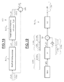
- FIGS. 17 to 21 Such a variant embodiment is illustrated more precisely in FIGS. 17 to 21 .
- the compensation processing in terms of clock shift (“skew mismatch compensation”) is performed in the first processing module MT 1 .
- the compensation processing in terms of gain is performed in a second module MT 2 here preceding the first module MT 1 .
- offset is performed in a third processing module here preceding the second processing module.
- the order of the three compensation processings may be arbitrary, although in practice performing the compensation in terms of gain before the compensation in terms of clock shifts is preferable.
- the M converters ADC m therefore deliver here M primary trains of samples a ⁇ tilde over (x) ⁇ m [k].
- the module MT 3 consequently delivers M corrected trains of corrected samples b ⁇ tilde over (x) ⁇ m [k] which are then considered for the module MT 2 as primary trains of primary samples.
- the module MT 2 therefore delivers in its turn M processed trains of processed samples ⁇ tilde over (x) ⁇ m [k] which are then considered to be the M original trains of original samples processed by the first processing module MT 1 which will deliver as output the M trains of processed samples ⁇ circumflex over (x) ⁇ m [k].
- the processings performed within the third processing module MT 3 on each of the M trains of samples are identical. They are for example performed in parallel.
- the processing module MT 3 is therefore configured to, for each current primary sample of this primary train, calculate a digital correction word mc m [k] belonging to a pseudo-random sequence of digital words, the average of whose values is equal or almost equal to the estimated value of the shift in terms of voltage ô m [k] of the corresponding converter ADC m , this shift value ô m [k] being computed on the basis of the values of a group of primary samples, here by performing a modified moving average.
- the processing module MT 3 is configured to subtract, in a subtracter STR, the digital correction word mc m [k] from the current primary sample a ⁇ tilde over (x) ⁇ m [k] so as to deliver the corrected sample b ⁇ tilde over (x) ⁇ m [k].
- the number L can here again for example be chosen to be of the order of a million.
- the primary samples a ⁇ tilde over (x) ⁇ m [k], arising from the converter ADC m , are in this example coded on n bits, for example 10 bits, just like the corrected samples b ⁇ tilde over (x) ⁇ m [k].
- the processing module MT 3 then comprises, associated with the converter ADC m , a first block BLC 1 m configured to, on the basis of the values a ⁇ tilde over (x) ⁇ m [k] of a group of primary samples, estimate here by performing a modified moving average of period L samples, the value of the shift ô m [k].
- o ⁇ m ⁇ [ k ] o ⁇ m ⁇ [ k - 1 ] - o ⁇ m ⁇ [ k - 1 ] L + a ⁇ x ⁇ m ⁇ [ k ] L ⁇ ⁇ ⁇ ⁇ m ⁇ [ 0 ] ⁇ ⁇ is ⁇ ⁇ taken ⁇ ⁇ equal ⁇ ⁇ to ⁇ ⁇ 0. ( XIII )
- the number L can be for example chosen equal to a power of 2 so as to avoid the use of a divider, this division operation then being able to be performed through a simple wiring.
- This offset (shift) is determined on a number of bits b that is greater than n.
- the number b can for example be taken equal to 16.
- the second block BLC 2 m of the processing module MT 3 associated also with the converter ADC m , comprises, as illustrated more particularly in FIG. 19 , a generator GEN configured to deliver an initial pseudo-random sequence of initial digital words a 1 m [k] whose values have a zero or almost zero average.
- the generator GEN can be for example of the type based on a linear feedback shift register (LFSR), whose structure and manner of operation are well known to the person skilled in the art.
- LFSR linear feedback shift register
- the shift register here comprises q flip-flops BSC 1 -BSCq connected in series and looped back by way of several logic gates, here three logic gates PL 1 , PL 2 , PL 3 , for example of the EXCLUSIVE OR type.
- the q outputs of the flip-flops deliver the q bits of an initial digital word a 1 m [k] of the pseudo-random sequence.
- the values of the words a 1 m [k] have a zero average when q is equal to infinity.
- q has a high value, for example 32, it may be estimated that the values of the words a 1 m [k] have a zero or almost zero average.
- random generator is merely a non-limiting particular example.
- Other types of random generators well known to the person skilled in the art can also be used such as for example a linear congruential generator.
- the block BLC 2 m also comprises a modification unit M 1 configured to deliver a modified digital word a 2 m [k] comprising in this example the b-n low-order bits of the initial digital word a 1 m [k] supplemented with n high-order bits all having the same logic value, here the logic value 0.
- a modification unit M 1 configured to deliver a modified digital word a 2 m [k] comprising in this example the b-n low-order bits of the initial digital word a 1 m [k] supplemented with n high-order bits all having the same logic value, here the logic value 0.
- the modification unit M 1 can be embodied simply by wiring, the n locations of a register that are intended to contain the word a 2 m [k] and that correspond to the n high-order bits being for example linked permanently to earth.
- the modified digital word a 2 m [k] consequently has b bits and is summed in summation unit SM, typically a conventional adder, with the shift ô m [k] also coded on b bits.
- summation unit SM typically a conventional adder
- the result of the summation is a word on b bits from which unit M 2 take away the b-n low-order bits so as to keep only n bits and thus form the digital correction word mc m [k].
- the unit M 2 can very well be embodied simply by wiring.
- the value of the digital correction word mc m [k] can therefore sometimes be greater than the value of the shift, sometimes lower, sometimes equal.
- the processing module MT 3 can be embodied by a specific integrated circuit (ASIC) or else optionally in a software manner within a microprocessor or else within a programmable logic array (“FPGA: Field Programmable Gate Array”).
- ASIC application-specific integrated circuit
- FPGA Field Programmable Gate Array
- This offset compensation processing can exhibit different variants.
- the modified moving average performed by each block BLC 1 m can be replaced with a fixed average calculated on a group of L samples or any other type of average.
- the b-n bits of the initial digital word are not necessarily the b-n low-order bits but may be b-n arbitrary bits of this initial digital word.
- the corrected current sample b ⁇ tilde over (x) ⁇ m [k] can be coded on a larger number of bits than that of the current primary sample a ⁇ tilde over (x) ⁇ m [k] delivered by the corresponding converter ADC m .
- the first block BLC 1 m takes n′ bits as input and still outputs b bits with b greater than n.
- the subtracter STR still subtracts the correction word of n bits, but now not from the current primary sample a ⁇ tilde over (x) ⁇ m [k] of n′ bits, but from a current intermediate sample of n bits which is obtained by supplementing the current primary sample a ⁇ tilde over (x) ⁇ m [k] with n-n′ low-order bits equal to 0.
- the gain mismatch compensation processing performed by the second processing module MT 2 it advantageously comprises an equalization of the mean powers of the various initial trains of initial samples, performed on the fly and at the tempo of delivery of the samples, on the basis of the values of the samples of these initial trains.
- the mean powers are determined here by modified moving averages of period L samples.
- the number L can be for example chosen here again to be of the order of a million.
- one of the initial trains is taken as reference train. In the example described here, this is the initial train of initial samples delivered by the converter ADC 0 .
- the second processing module MT 2 comprises a first block BLC 10 configured to perform on the fly and at the tempo of delivery of the initial samples b ⁇ tilde over (x) ⁇ m [k], for each of the other trains, an estimation of the relative gain between the corresponding converter and the converter ADC 0 delivering the reference train.
- the second processing module MT 2 also comprises a second block BLC 20 configured to perform on the fly and at the tempo of delivery of the initial samples b ⁇ tilde over (x) ⁇ m [k], a correction of the values of the samples of each of the other trains by the corresponding relative gain.
- the first block BLC 10 comprises a first circuit CR 0 configured to determine the modified moving average of the absolute values of the initial samples b ⁇ tilde over (x) ⁇ 0 [k] of the reference train.
- the first block BLC 10 also comprises a second circuit CR m configured to determine the modified moving average of the absolute values of the initial samples b ⁇ tilde over (x) ⁇ m [k] of the train arising from the converter ADC m .
- the first block BLC 10 further comprises a third circuit DIV m configured to determine the ratio between the average of the absolute values of the samples b ⁇ tilde over (x) ⁇ 0 [k] of the reference train and the average of the absolute values of the samples b ⁇ tilde over (x) ⁇ m [k] of the train arising from the converter ADC m , the ratio being representative of the estimated gain ⁇ m [k] of the converter ADC m in relation to the converter ADC 0 .
- a third circuit DIV m configured to determine the ratio between the average of the absolute values of the samples b ⁇ tilde over (x) ⁇ 0 [k] of the reference train and the average of the absolute values of the samples b ⁇ tilde over (x) ⁇ m [k] of the train arising from the converter ADC m , the ratio being representative of the estimated gain ⁇ m [k] of the converter ADC m in relation to the converter ADC 0 .
- the first circuit CR 0 comprises a first sub-circuit ABS 0 configured to deliver the absolute value of the sample b ⁇ tilde over (x) ⁇ 0 [k] present at input.
- the sub-circuit ABS 0 tests the value of the sign bit of the sample.
- the sub-circuit ABS 0 delivers the data bits of the sample as they are, then representing the absolute value of the sample.
- the sub-circuit ABS 0 inverts the data bits of the sample and adds 1 to the intermediate sample thus obtained, these new data bits then representing the absolute value of the sample.
- the sub-circuit ABS 0 can thus be embodied in a very simple manner, in part by wiring and by using a multiplexer, inverters and an adder.
- the first circuit CR 0 also comprises a sub-circuit MYG 0 configured to, on the basis of the values b ⁇ tilde over (x) ⁇ m [k] of a group of samples, determine here by performing a modified moving average of period L samples, the value of the following expression (formula XIV):
- the second circuit CR m comprises a sub-circuit ABS m and a sub-circuit MYG m , that are structurally and functionally identical to the sub-circuits ABS 0 and MYG 0 .
- the sub-circuit MYG m is configured to, on the basis of the values b ⁇ tilde over (x) ⁇ m [k] of a group of samples, determine here by performing a modified moving average of period L samples, the value of the following expression (formula XV)
- the number L can be for example chosen equal to a power of 2 so as to avoid the use of a divider, this division operation then being able to be performed through simple wiring.
- a divider DIVm thereafter calculates the ratio between these two expressions to determine the inverse of the relative gain ⁇ m [k] of the converter ADC m with respect to the converter ADC 0 , associated with the current initial sample b ⁇ tilde over (x) ⁇ m [k] (formula XVI):
- the second block BLC 20 m comprises circuitry configured to divide values of the samples of the train arising from the converter ADCm by the estimated relative gain.
- This circuitry is here a multiplier which multiplies the current initial sample b ⁇ tilde over (x) ⁇ m [k] by the inverse of the relative gain (formula XVII) to deliver the processed sample ⁇ tilde over (x) ⁇ m [k]:
- x ⁇ m ⁇ [ k ] x ⁇ m ⁇ [ k ] ⁇ x ⁇ 1 g ⁇ m ⁇ [ k ] ( XVII )
- the processing module MT 2 can also be embodied by an ASIC or else optionally in a software manner within a microprocessor, or else within an FPGA.
- the device DIS as a whole can be embodied within a single ASIC or single FPGA or else in a software manner within a single microprocessor.
- FIGS. 22 to 25 illustrate simulation results obtained for a device of the type of that illustrated in FIG. 17 , devoid however of the processing module MT 3 , since it is connected to a conversion structure with temporal interleaving whose temporally interleaved converters are not assumed to exhibit mismatch in terms of shift (“offset”).
- the analog signal is a signal having a single tone TN.
- the spectral power of the sampled signal has been represented as ordinate and the normalized frequency F/Fs as abscissa, where F denotes the frequency of the sampled signal.
- the sampled signal delivered as output from the device DIS still exhibits the tone TN but, this time, the spurious spectral lines have been eliminated.
- the input signal is a multitone signal possessing several useful tones TN i .
Landscapes
- Engineering & Computer Science (AREA)
- Theoretical Computer Science (AREA)
- Analogue/Digital Conversion (AREA)
Abstract
Description
|r m |=|δt m /Ts|
is much less than 1, typically less than 1%. rm here denotes a shift coefficient representative of the clock shift between the original train arising from the converter ADCm and the reference train, in this instance the train arising from the converter ADC0.
D(z)=Σk=1 K
-
- when the row index is equal to the column index of the matrix, the coefficients are equal to 1;
- when the column index is equal to the row index plus or
minus 1 modulo M, the corresponding coefficient is equal to −0.5; - the coefficient is equal to 0 for all the other values of the row and column indices.
F′=(H T H)−1 H T (IV)
{circumflex over (x)} m [k]={tilde over (x)}[kM+m]−{circumflex over (r)} m x D [kM+m] (V)
F=(H T H)−1 H T (XI)
b{tilde over (x)} m [k]=a{tilde over (x)} m [k]−mc m [k] (XII)
Claims (40)
Applications Claiming Priority (2)
| Application Number | Priority Date | Filing Date | Title |
|---|---|---|---|
| FR1351448 | 2013-02-20 | ||
| FR1351448A FR3002391A1 (en) | 2013-02-20 | 2013-02-20 | METHOD AND DEVICE FOR IN PARTICULAR COMPENSATING FOR THE DISPAIRING OF TIMER OFFSETS OF MULTIPLE TEMPORALLY INTERLACED ANALOGUE / DIGITAL CONVERTERS |
Publications (2)
| Publication Number | Publication Date |
|---|---|
| US20140232575A1 US20140232575A1 (en) | 2014-08-21 |
| US8890728B2 true US8890728B2 (en) | 2014-11-18 |
Family
ID=49111292
Family Applications (1)
| Application Number | Title | Priority Date | Filing Date |
|---|---|---|---|
| US14/179,993 Active US8890728B2 (en) | 2013-02-20 | 2014-02-13 | Method and device for use with analog to digital converter |
Country Status (2)
| Country | Link |
|---|---|
| US (1) | US8890728B2 (en) |
| FR (1) | FR3002391A1 (en) |
Cited By (7)
| Publication number | Priority date | Publication date | Assignee | Title |
|---|---|---|---|---|
| US20150263747A1 (en) * | 2014-03-12 | 2015-09-17 | Texas Instruments Incorporated | Close-in tones |
| US9941893B2 (en) * | 2016-04-19 | 2018-04-10 | Texas Instruments Incorporated | Pattern based estimation of errors in ADC |
| US10784882B2 (en) * | 2019-01-23 | 2020-09-22 | Global Unichip Corporation | Analog to digital converter device and method of calibrating clock skew |
| US10868556B2 (en) * | 2019-03-29 | 2020-12-15 | Intel Corporation | Apparatus for calibrating a time-interleaved analog-to-digital converter |
| US11552646B2 (en) | 2020-06-24 | 2023-01-10 | Stmicroelectronics International N.V. | Timing skew mismatch calibration for time interleaved analog to digital converters |
| US11641210B1 (en) | 2021-11-18 | 2023-05-02 | Caelus Technologies Limited | Matrix processor generating SAR-searched input delay adjustments to calibrate timing skews in a multi-channel interleaved analog-to-digital converter (ADC) |
| US11646747B1 (en) | 2021-11-18 | 2023-05-09 | Caelus Technologies Limited | Multi-channel interleaved analog-to-digital converter (ADC) using overlapping multi-phase clocks with SAR-searched input-clock delay adjustments and background offset and gain correction |
Families Citing this family (6)
| Publication number | Priority date | Publication date | Assignee | Title |
|---|---|---|---|---|
| US8611480B1 (en) * | 2007-03-26 | 2013-12-17 | Marvell International Ltd. | Optimal decoding of transmit diversity code with varying channel characteristics |
| US10132663B2 (en) * | 2015-04-30 | 2018-11-20 | Goodrich Corporation | Self-calibrating linear voltage differential transformer demodulator |
| US10256831B2 (en) | 2016-09-21 | 2019-04-09 | Analog Devices Global | Method and apparatus to reduce effect of dielectric absorption in SAR ADC |
| WO2020043305A1 (en) * | 2018-08-31 | 2020-03-05 | Telefonaktiebolaget Lm Ericsson (Publ) | Control of a time-interleaved analog-to-digital converter |
| US11750166B2 (en) | 2021-01-13 | 2023-09-05 | Marvell Asia Pte. Ltd. | Method and device for high bandwidth receiver for high baud-rate communications |
| US11309904B1 (en) * | 2021-02-24 | 2022-04-19 | Marvell Asia Pte Ltd. | Method and device for synchronization of large-scale systems with multiple time interleaving sub-systems |
Citations (4)
| Publication number | Priority date | Publication date | Assignee | Title |
|---|---|---|---|---|
| US7138933B2 (en) * | 2005-04-26 | 2006-11-21 | Analog Devices, Inc. | Time-interleaved signal converter systems with reduced timing skews |
| US7403875B2 (en) | 2006-04-12 | 2008-07-22 | Infineon Technologies Ag | System for reconstruction of non-uniformly sampled signals |
| US8159377B2 (en) | 2010-08-31 | 2012-04-17 | Texas Instruments Incorporated | System, method, and circuitry for blind timing mismatch estimation of interleaved analog-to-digital converters |
| EP2503696A1 (en) | 2006-06-30 | 2012-09-26 | Signal Processing Devices Sweden AB | Time-interleaved analog-to-digital converter system |
-
2013
- 2013-02-20 FR FR1351448A patent/FR3002391A1/en not_active Withdrawn
-
2014
- 2014-02-13 US US14/179,993 patent/US8890728B2/en active Active
Patent Citations (4)
| Publication number | Priority date | Publication date | Assignee | Title |
|---|---|---|---|---|
| US7138933B2 (en) * | 2005-04-26 | 2006-11-21 | Analog Devices, Inc. | Time-interleaved signal converter systems with reduced timing skews |
| US7403875B2 (en) | 2006-04-12 | 2008-07-22 | Infineon Technologies Ag | System for reconstruction of non-uniformly sampled signals |
| EP2503696A1 (en) | 2006-06-30 | 2012-09-26 | Signal Processing Devices Sweden AB | Time-interleaved analog-to-digital converter system |
| US8159377B2 (en) | 2010-08-31 | 2012-04-17 | Texas Instruments Incorporated | System, method, and circuitry for blind timing mismatch estimation of interleaved analog-to-digital converters |
Non-Patent Citations (12)
| Title |
|---|
| Abbaszadeh, et al., "A New FPGA-Based Postprocessor Architecture for Channel Mismatch Correction of Time Interleaved ADCS," Signal Processing Systems, Oct. 7, 2009, 6 pages. |
| Divi, et al., "Blind Calibration of Timing Skew in Time-Interleaved Analog-to-Digital Converters," IEEE Journal of Selected Topics in Signal Processing, vol. 3, No. 3, Jun. 2009, 14 pages. |
| Elbornsson, et al., "Blind Adaptive Equalization of Mismatch Errors in a Time-Interleaved A/D Converter System," IEEE Transactions on Circuits and System-I: Regular Papers, vol. 51, No. 1, Jan. 2001, 8 pages. |
| Elbornsson, et al., "Blind Adaptive Equalization of Mismatch Errors in a Time-Interleaved A/D Converter System," IEEE Transactions on Circuits and System—I: Regular Papers, vol. 51, No. 1, Jan. 2001, 8 pages. |
| Huang, et al., "A 10-bit 400-MS/s 36-mW Interleaved ADC," IEEE International Symposium on Radio-Frequency Integration Technology, Nov. 30-Dec. 2, 2011, Beijing, China, 4 pages. |
| Huang, et al., "Blind Calibration of Timing Offsets for Four-Channel Time-Interleaved ADCs," IEEE Transactions on Circuits and Systems-I: Regular Papers, vol. 54, No. 4, Apr. 2007, 14 pages. |
| Huang, et al., "Blind Calibration of Timing Offsets for Four-Channel Time-Interleaved ADCs," IEEE Transactions on Circuits and Systems—I: Regular Papers, vol. 54, No. 4, Apr. 2007, 14 pages. |
| Jamal, et al., "A 10-b 120-Msample/s Time-Interleaved Analog-to-Digital Converter With Digital Background Calibration," IEEE Journal of Solid-State Circuits, vol. 37, No. 12, Dec. 2002, 10 pages. |
| Oppenheim, et al., "Discrete-Time Differentiators," Prentice Hall, Inc. Jan. 1989, 4 pages. |
| Saleem, "Adaptive Blind Calibration of Gain and Timing Mismatches in a Time-Interleaved ADC-A Performance Analysis," Instrumentation and Measurement Technology Conference, May 13, 2012, 6 pages. |
| Shu, et al., "A 10~15-bit 60-MS/s Floating-Point ADC With Digital Gain and Offset Calibration," IEEE Journal of Solid-State Circuits, vol. 44, No. 9, Sep. 2009, 10 pages. |
| Shu, et al., "A 10˜15-bit 60-MS/s Floating-Point ADC With Digital Gain and Offset Calibration," IEEE Journal of Solid-State Circuits, vol. 44, No. 9, Sep. 2009, 10 pages. |
Cited By (10)
| Publication number | Priority date | Publication date | Assignee | Title |
|---|---|---|---|---|
| US20150263747A1 (en) * | 2014-03-12 | 2015-09-17 | Texas Instruments Incorporated | Close-in tones |
| US9160358B2 (en) * | 2014-03-12 | 2015-10-13 | Texas Instruments Incorporated | Close-in tones |
| US9941893B2 (en) * | 2016-04-19 | 2018-04-10 | Texas Instruments Incorporated | Pattern based estimation of errors in ADC |
| US10320405B2 (en) | 2016-04-19 | 2019-06-11 | Texas Instruments Incorporated | Pattern based estimation of errors in ADC |
| US10784882B2 (en) * | 2019-01-23 | 2020-09-22 | Global Unichip Corporation | Analog to digital converter device and method of calibrating clock skew |
| US10868556B2 (en) * | 2019-03-29 | 2020-12-15 | Intel Corporation | Apparatus for calibrating a time-interleaved analog-to-digital converter |
| US11552646B2 (en) | 2020-06-24 | 2023-01-10 | Stmicroelectronics International N.V. | Timing skew mismatch calibration for time interleaved analog to digital converters |
| US12009830B2 (en) | 2020-06-24 | 2024-06-11 | Stmicroelectronics International N.V. | Timing skew mismatch calibration for time interleaved analog to digital converters |
| US11641210B1 (en) | 2021-11-18 | 2023-05-02 | Caelus Technologies Limited | Matrix processor generating SAR-searched input delay adjustments to calibrate timing skews in a multi-channel interleaved analog-to-digital converter (ADC) |
| US11646747B1 (en) | 2021-11-18 | 2023-05-09 | Caelus Technologies Limited | Multi-channel interleaved analog-to-digital converter (ADC) using overlapping multi-phase clocks with SAR-searched input-clock delay adjustments and background offset and gain correction |
Also Published As
| Publication number | Publication date |
|---|---|
| US20140232575A1 (en) | 2014-08-21 |
| FR3002391A1 (en) | 2014-08-22 |
Similar Documents
| Publication | Publication Date | Title |
|---|---|---|
| US8890728B2 (en) | Method and device for use with analog to digital converter | |
| Salib et al. | A high-precision time skew estimation and correction technique for time-interleaved ADCs | |
| Matsuno et al. | All-digital background calibration technique for time-interleaved ADC using pseudo aliasing signal | |
| Liu et al. | Adaptive calibration of channel mismatches in time-interleaved ADCs based on equivalent signal recombination | |
| US20170117914A1 (en) | Method and apparatus for providing digital background calibration for mismatches in m-channel time-interleved adcs (ti-adcs) | |
| US11552646B2 (en) | Timing skew mismatch calibration for time interleaved analog to digital converters | |
| US8564462B2 (en) | Digital correction techniques for data converters | |
| US8421656B2 (en) | Time-interleaved analog-to-digital conversion circuit having polyphase correction filter | |
| US20130049999A1 (en) | Analog/digital converter and semiconductor integrated circuit device | |
| US7348908B2 (en) | Linearity corrector using filter products | |
| Schmidt et al. | Efficient estimation and correction of mismatch errors in time-interleaved ADCs | |
| KR20100080391A (en) | Error estimation and correction in a two-channel time-interleaved analog-to-digital converter | |
| US9178525B2 (en) | Mismatch corrector | |
| Le Duc et al. | A fully digital background calibration of timing skew in undersampling TI-ADC | |
| JP2013500662A (en) | Method for correcting analog defects in parallel analog-to-digital converters, especially for the use of multi-standard software defined radios and / or cognitive radios | |
| US20250337423A1 (en) | Time-interleaved adc mismatch correction method and time-interleaved adc | |
| JP3752237B2 (en) | A / D converter | |
| US9762254B2 (en) | Continuous tracking of mismatch correction in both analog and digital domains in an interleaved ADC | |
| Salib et al. | A low-complexity correlation-based time skew estimation technique for time-interleaved SAR ADCs | |
| Salib et al. | Time-skew estimation for random sampling sequence time-interleaved adcs | |
| Ta et al. | Fully digital background calibration technique for channel mismatches in TIADCs | |
| KR101691367B1 (en) | METHOD OF PROVIDING DIGITAL BACKGROUND CALIBRATION FOR MISMATCHES IN M-CHANNEL TI-ADCs AND THE APPARATUS THEREOF | |
| US10735010B1 (en) | CDR-based timing skew calibration | |
| Xu et al. | Recursive filters for time-interleaved ADC mismatch compensation | |
| Divi et al. | Scalable blind calibration of timing skew in high-resolution time-interleaved ADCs |
Legal Events
| Date | Code | Title | Description |
|---|---|---|---|
| AS | Assignment |
Owner name: STMICROELECTRONICS SA, FRANCE Free format text: ASSIGNMENT OF ASSIGNORS INTEREST;ASSIGNORS:LE DORTZ, NICOLAS;SIMON, THIERRY;URARD, PASCAL;AND OTHERS;SIGNING DATES FROM 20140202 TO 20140210;REEL/FRAME:032214/0237 |
|
| STCF | Information on status: patent grant |
Free format text: PATENTED CASE |
|
| MAFP | Maintenance fee payment |
Free format text: PAYMENT OF MAINTENANCE FEE, 4TH YEAR, LARGE ENTITY (ORIGINAL EVENT CODE: M1551) Year of fee payment: 4 |
|
| MAFP | Maintenance fee payment |
Free format text: PAYMENT OF MAINTENANCE FEE, 8TH YEAR, LARGE ENTITY (ORIGINAL EVENT CODE: M1552); ENTITY STATUS OF PATENT OWNER: LARGE ENTITY Year of fee payment: 8 |
|
| AS | Assignment |
Owner name: STMICROELECTRONICS INTERNATIONAL N.V., SWITZERLAND Free format text: ASSIGNMENT OF ASSIGNORS INTEREST;ASSIGNOR:STMICROELECTRONICS SA;REEL/FRAME:060620/0769 Effective date: 20220630 |