US8887892B2 - Chain for rolling elements - Google Patents

Chain for rolling elements Download PDF

Info

Publication number
US8887892B2
US8887892B2 US13/777,716 US201313777716A US8887892B2 US 8887892 B2 US8887892 B2 US 8887892B2 US 201313777716 A US201313777716 A US 201313777716A US 8887892 B2 US8887892 B2 US 8887892B2
Authority
US
United States
Prior art keywords
ribs
chain
retainer
thickness
carrier belt
Prior art date
Legal status (The legal status is an assumption and is not a legal conclusion. Google has not performed a legal analysis and makes no representation as to the accuracy of the status listed.)
Active, expires
Application number
US13/777,716
Other versions
US20140060996A1 (en
Inventor
Ming-Che Hsu
Current Assignee (The listed assignees may be inaccurate. Google has not performed a legal analysis and makes no representation or warranty as to the accuracy of the list.)
Chieftek Precision Co Ltd CPC
Original Assignee
Chieftek Precision Co Ltd CPC
Priority date (The priority date is an assumption and is not a legal conclusion. Google has not performed a legal analysis and makes no representation as to the accuracy of the date listed.)
Filing date
Publication date
Application filed by Chieftek Precision Co Ltd CPC filed Critical Chieftek Precision Co Ltd CPC
Assigned to Chieftek Precision Co., Ltd. reassignment Chieftek Precision Co., Ltd. ASSIGNMENT OF ASSIGNORS INTEREST (SEE DOCUMENT FOR DETAILS). Assignors: HSU, MING-CHE
Publication of US20140060996A1 publication Critical patent/US20140060996A1/en
Application granted granted Critical
Publication of US8887892B2 publication Critical patent/US8887892B2/en
Active legal-status Critical Current
Adjusted expiration legal-status Critical

Links

Images

Classifications

    • FMECHANICAL ENGINEERING; LIGHTING; HEATING; WEAPONS; BLASTING
    • F16ENGINEERING ELEMENTS AND UNITS; GENERAL MEASURES FOR PRODUCING AND MAINTAINING EFFECTIVE FUNCTIONING OF MACHINES OR INSTALLATIONS; THERMAL INSULATION IN GENERAL
    • F16CSHAFTS; FLEXIBLE SHAFTS; ELEMENTS OR CRANKSHAFT MECHANISMS; ROTARY BODIES OTHER THAN GEARING ELEMENTS; BEARINGS
    • F16C33/00Parts of bearings; Special methods for making bearings or parts thereof
    • F16C33/30Parts of ball or roller bearings
    • F16C33/38Ball cages
    • F16C33/3825Ball cages formed as a flexible belt, e.g. spacers connected by a thin film
    • FMECHANICAL ENGINEERING; LIGHTING; HEATING; WEAPONS; BLASTING
    • F16ENGINEERING ELEMENTS AND UNITS; GENERAL MEASURES FOR PRODUCING AND MAINTAINING EFFECTIVE FUNCTIONING OF MACHINES OR INSTALLATIONS; THERMAL INSULATION IN GENERAL
    • F16CSHAFTS; FLEXIBLE SHAFTS; ELEMENTS OR CRANKSHAFT MECHANISMS; ROTARY BODIES OTHER THAN GEARING ELEMENTS; BEARINGS
    • F16C29/00Bearings for parts moving only linearly
    • F16C29/04Ball or roller bearings
    • F16C29/06Ball or roller bearings in which the rolling bodies circulate partly without carrying load
    • BPERFORMING OPERATIONS; TRANSPORTING
    • B65CONVEYING; PACKING; STORING; HANDLING THIN OR FILAMENTARY MATERIAL
    • B65GTRANSPORT OR STORAGE DEVICES, e.g. CONVEYORS FOR LOADING OR TIPPING, SHOP CONVEYOR SYSTEMS OR PNEUMATIC TUBE CONVEYORS
    • B65G39/00Rollers, e.g. drive rollers, or arrangements thereof incorporated in roller-ways or other types of mechanical conveyors 
    • B65G39/10Arrangements of rollers
    • B65G39/12Arrangements of rollers mounted on framework
    • FMECHANICAL ENGINEERING; LIGHTING; HEATING; WEAPONS; BLASTING
    • F16ENGINEERING ELEMENTS AND UNITS; GENERAL MEASURES FOR PRODUCING AND MAINTAINING EFFECTIVE FUNCTIONING OF MACHINES OR INSTALLATIONS; THERMAL INSULATION IN GENERAL
    • F16CSHAFTS; FLEXIBLE SHAFTS; ELEMENTS OR CRANKSHAFT MECHANISMS; ROTARY BODIES OTHER THAN GEARING ELEMENTS; BEARINGS
    • F16C2240/00Specified values or numerical ranges of parameters; Relations between them
    • F16C2240/40Linear dimensions, e.g. length, radius, thickness, gap
    • F16C2240/60Thickness, e.g. thickness of coatings

Definitions

  • the present invention relates to a chain for rolling elements, and more particularly, to a carrier belt with holes and retainers connected alternatively to each other along the longitudinal direction of the carrier belt and having ribs so as to improve the connecting stiffness between strips and retainers and keep the flexibility of the chain to be even.
  • the conventional chain for rolling elements usually comprises multiple balls rotatably retained in the holes of the carrier belt and between retainers.
  • the adjacent balls do not interfere to each other and the chain is used for high speed circulation movement of precise mechanism such as linear slide assembly.
  • Taiwan Patent Application No. 201122262 discloses a chain which comprises a carrier belt “I” and multiple holes “I 1 ” are defied along the longitudinal direction of the carrier belt “I” so as to receive balls “K” in the holes “I 1 ”.
  • Multiple retainers “J” are alternatively located between the holes “I 1 ” so as to separate the balls “K” to ensure that the balls “K” to operate smoothly.
  • the thickness of the chain varies in different sections along the longitudinal direction so that when the chain moves over a turning path “L 1 ”, the carrier belt “I” cannot smoothly pass through the turning path “L 1 ” and affects the operation of the chain.
  • U.S. Pat. No. 6,364,086 discloses a chain of rolling elements which comprises two side strips and multiple retainers.
  • the multiple retainers are connected between the two side strips so as to form multiple holes.
  • the gaps allow the chain to have more flexibility. Consequently, the carrier belt “I” can smoothly pass through the turning path “L 1 ”.
  • the connection portion between the side strips and the retainers are weaker and suffered by significant pressure such that shorten the life of the chain.
  • the present invention intends to provide a chain for rolling elements which have better flexibility and strength and longer life so as to bear higher operation speed and heavier operation load and improve the shortcomings of the conventional chain for rolling elements.
  • the present invention relates to a chain for rolling elements and comprises a carrier belt having first and second side strip on two sides thereof, and multiple holes are defined in the carrier belt and located between the first and second side strips. Each hole has a first opening end and a second opening end. Multiple retainers are connected to the carrier belt and located alternatively with respect to the holes. Multiple first ribs are connected between the first side strip and the retainer. Multiple second ribs are connected between the second side strip and the retainer. Each of the first and second side strips has a thickness and each of the first and second ribs has a thickness T 2 which is smaller than T 1 . The first and second ribs reinforce connections between the first and second side strips and the retainers so that the chain has even flexibility.
  • the preferable thickness T 1 is larger than 0.1 mm to easily manufacturing the chain by way of injection molding, and the preferable ratio between T 2 /T 1 is less than 50% for providing better flexibility of the chain.
  • each of the first ribs increases from the first opening end toward the second opening end of the hole corresponding thereto, and the thickness of each of the second ribs increases from the second opening end toward the first opening end of the hole corresponding thereto.
  • the thickness of each of the first and second ribs increases from the mediate portion of each of the first and second side strips toward the first and second opening ends of the hole.
  • a straight side or a curved side is formed on the first and second ribs and located adjacent to the holes corresponding thereto.
  • each of the first ribs increases from the retainer connected to the first rib toward a direction away from the retainer.
  • the thickness of each of the second ribs increases from the retainer connected to the second rib toward a direction away from the retainer.
  • the first and second ribs reinforce connections between the first and second side strips and the retainers so that the chain has even flexibility.
  • the chain of the present invention easily passes through the turning portion at high speed.
  • the chain of the present invention can bear higher load and operates at higher speed than the conventional one.
  • FIG. 1 is a perspective view to show the chain of the present invention
  • FIG. 2 is a plane view of the chain of the present invention
  • FIG. 3 is a cross sectional view taken along line A-A of FIG. 2 ;
  • FIG. 4 shows that the chain of the present invention forms a curve
  • FIG. 5 shows that the chain of the present invention is used in a slide assembly and passing through a turning portion of the slide assembly
  • FIG. 6 shows a portion of the second embodiment of the chain of the present invention
  • FIG. 7 shows a portion of the third embodiment of the chain of the present invention.
  • FIG. 8 shows a portion of the fourth embodiment of the chain of the present invention.
  • FIG. 9 is a cross sectional view taken along line B-B of FIG. 8 ;
  • FIG. 10 is a perspective view to show the conventional chain
  • FIG. 11 shows that the conventional chain forms a curve
  • FIG. 12 shows that the conventional chain is used in a slide assembly and passing through a turning portion of the slide assembly.
  • the chain “P” for rolling elements of the present invention comprises a flat carrier belt 1 which extends along the longitudinal direction “A” and has a first side strip 12 and a second side strip 13 on two sides thereof.
  • Multiple holes 11 are defined in the carrier belt 1 along the longitudinal direction “A” and located between the first and second side strips 12 , 13 .
  • the first and second side strips 12 , 13 are located adjacent to the holes 11 .
  • Each hole 11 has a first opening end 111 and a second opening end 112 , and multiple retainers 2 are connected to the carrier belt 1 and located alternatively with respect to the holes 11 .
  • first ribs 14 are connected between the first side strip 12 and the retainer 2 , and each of the first ribs 14 is located adjacent the hole 11 corresponding thereto.
  • Multiple second ribs 15 are connected between the second side strip 13 and the retainer 2 , and each of the second ribs 15 is located adjacent the hole 11 corresponding thereto.
  • Each of the first and second side strips 12 , 13 has a thickness T 1
  • each of the first and second ribs 14 , 15 has a thickness T 2 which is smaller than T 1 .
  • thickness T 1 is larger than 0.1 mm to easily manufacture the chain by way of injection molding, and the preferable ratio between T 2 /T 1 is less than 50% for providing better flexibility of the chain “P”. As shown in FIG.
  • a first curved side 141 is formed on the first rib 14 and located adjacent to the hole 11 corresponding thereto.
  • a second curved side 151 is formed on the second rib 15 and located adjacent to the hole 11 corresponding thereto.
  • the thickness T 2 of each of the first ribs 14 increases from the first opening end 111 toward the second opening end 112 of the hole 11 corresponding thereto.
  • the thickness T 2 of each of the second ribs 15 increases from the second opening end 112 toward the first opening end 111 of the hole 11 corresponding thereto.
  • the first rib 14 is connected between the first side strip 12 and the retainer 2
  • the second rib 15 is connected to the second side strip 13 and the retainer 2
  • the first and second ribs 14 , 15 reinforce the connections between the first and second side strips 12 , 13 and the retainers 2 so that the flat carrier belt 1 and chain have even flexibility and can form smooth curves.
  • the chain “P” having the balls 3 is installed in the circulating passage/loop-like track of the linear slide assembly 4 . When the chain “p” with balls 3 passes through the turning portion 41 of the circulating passage, the flat carrier belt 1 forms a smooth curve in the turning portion 41 .
  • the stability and smoothness of the chain “p” during the passing of the turning portion 41 are improved. Further, because of the reinforcement of the connections between the first and second side strips 12 , 13 and the retainers 2 , the chain “P” can bear higher load and move at higher speed than the conventional one in the linear slide assembly 4 .
  • FIG. 6 shows the second embodiment, wherein the chain comprises a flat carrier belt 1 A which has a first side strip 12 A and a second side strip 13 A on two sides thereof.
  • Multiple holes 11 A are defined in the carrier belt 1 A and located between the first and second side strips 12 A, 13 A.
  • the first and second side strips 12 A, 13 A are located adjacent to the holes 11 A.
  • Each hole 11 A has a first opening end 111 A and a second opening end 112 A, and multiple retainers 2 A are connected to the carrier belt 1 A and located alternatively with respect to the holes 11 A.
  • Multiple first ribs 14 A are connected between the first side strip 12 A and the retainer 2 A, and each of the first ribs 14 A is located adjacent the hole 11 A corresponding thereto.
  • Multiple second ribs 15 A are connected between the second side strip 13 A and the retainer 2 A, and each of the second ribs 15 A is located adjacent the hole 11 A corresponding thereto.
  • the thickness of each of the first and second ribs 14 A, 15 A increases from the mediate portion of each of the first and second side strips 12 A, 13 A toward the first and second opening ends 111 A, 112 A of the hole 11 A.
  • FIG. 7 shows the third embodiment, wherein the chain comprises a flat carrier belt 1 B which has a first side strip 12 B and a second side strip 13 B on two sides thereof.
  • Multiple holes 11 B are defined in the carrier belt 1 B and located between the first and second side strips 12 B, 13 B.
  • the first and second side strips 12 B, 13 B are located adjacent to the holes 11 B.
  • Multiple retainers 2 B are connected to the carrier belt 1 B and located alternatively with respect to the holes 11 B.
  • Multiple first ribs 14 B are connected between the first side strip 12 B and the retainer 2 B, and each of the first ribs 14 B is located adjacent the hole 11 B corresponding thereto.
  • Multiple second ribs 15 B are connected between the second side strip 13 B and the retainer 2 B, and each of the second ribs 15 B is located adjacent the hole 11 B corresponding thereto.
  • a first straight side 141 B is formed on the first rib 14 B and located adjacent to the hole 11 B corresponding thereto.
  • a second straight side 151 B is formed on the second rib 15 B and located adjacent to the hole 11 B corresponding thereto.
  • the carrier belt 1 B can generate smooth curves.
  • FIGS. 8 and 9 shows the fourth embodiment, wherein the chain comprises a flat carrier belt 1 C which has a first side strip 12 C and a second side strip 13 C on two sides thereof.
  • Multiple holes 11 C are defined in the carrier belt 1 C and located between the first and second side strips 12 C, 13 C.
  • the first and second side strips 12 C, 13 C are located adjacent to the holes 11 C.
  • Multiple retainers 2 C are connected to the carrier belt 1 C and located alternatively with respect to the holes 11 C.
  • Multiple first ribs 14 C are connected between the first side strip 12 C and the retainer 2 C, and each of the first ribs 14 C is located adjacent the hole 11 C corresponding thereto.
  • Each of the second ribs 15 C are connected between the second side strip 13 C and the retainer 2 C, and each of the second ribs 15 C is located adjacent the hole 11 C corresponding thereto.
  • the thickness of each of the first ribs 14 C increases from the retainer 2 C connected to the first rib 14 C toward the direction away from the retainer 2 C.
  • the thickness of each of the second ribs 15 C increases from the retainer 2 C connected to the second rib 15 C toward the direction away from the retainer 2 C.
  • the carrier belt 1 C therefore may have more even flexibility and can form smoother curves than the previous embodiments of the chain.

Landscapes

  • Engineering & Computer Science (AREA)
  • General Engineering & Computer Science (AREA)
  • Mechanical Engineering (AREA)
  • Bearings For Parts Moving Linearly (AREA)
  • Rolling Contact Bearings (AREA)

Abstract

A chain for rolling elements includes a carrier belt having first and second side strip on two sides thereof, and multiple holes are defined in the carrier belt and located between the first and second side strips. Each hole has a first opening end and a second opening end. Multiple retainers are connected to the carrier belt and located alternatively with respect to the holes. Multiple first ribs are connected between the first side strip and the retainer. Multiple second ribs are connected between the second side strip and the retainer. Each of the first and second side strips has a thickness T1, and each of the first and second ribs has a thickness T2 which is smaller than T1. The first and second ribs reinforce connections between the first and second side strips and the retainers so that the chain has even flexibility and can operate smoothly.

Description

FIELD OF THE INVENTION
The present invention relates to a chain for rolling elements, and more particularly, to a carrier belt with holes and retainers connected alternatively to each other along the longitudinal direction of the carrier belt and having ribs so as to improve the connecting stiffness between strips and retainers and keep the flexibility of the chain to be even.
BACKGROUND OF THE INVENTION
The conventional chain for rolling elements usually comprises multiple balls rotatably retained in the holes of the carrier belt and between retainers. The adjacent balls do not interfere to each other and the chain is used for high speed circulation movement of precise mechanism such as linear slide assembly.
As shown in FIGS. 10 to 12, the Taiwan Patent Application No. 201122262 discloses a chain which comprises a carrier belt “I” and multiple holes “I1” are defied along the longitudinal direction of the carrier belt “I” so as to receive balls “K” in the holes “I1”. Multiple retainers “J” are alternatively located between the holes “I1” so as to separate the balls “K” to ensure that the balls “K” to operate smoothly. However, the thickness of the chain varies in different sections along the longitudinal direction so that when the chain moves over a turning path “L1”, the carrier belt “I” cannot smoothly pass through the turning path “L1” and affects the operation of the chain.
U.S. Pat. No. 6,364,086 discloses a chain of rolling elements which comprises two side strips and multiple retainers. The multiple retainers are connected between the two side strips so as to form multiple holes. Wherein, when balls are received in the holes, there are gaps between the retainers and the balls so that when the chain moves over the turning path “L1”, the gaps allow the chain to have more flexibility. Consequently, the carrier belt “I” can smoothly pass through the turning path “L1”. Nevertheless, comparing to the Taiwan Patent Application No. 201122262, the connection portion between the side strips and the retainers are weaker and suffered by significant pressure such that shorten the life of the chain.
The present invention intends to provide a chain for rolling elements which have better flexibility and strength and longer life so as to bear higher operation speed and heavier operation load and improve the shortcomings of the conventional chain for rolling elements.
SUMMARY OF THE INVENTION
The present invention relates to a chain for rolling elements and comprises a carrier belt having first and second side strip on two sides thereof, and multiple holes are defined in the carrier belt and located between the first and second side strips. Each hole has a first opening end and a second opening end. Multiple retainers are connected to the carrier belt and located alternatively with respect to the holes. Multiple first ribs are connected between the first side strip and the retainer. Multiple second ribs are connected between the second side strip and the retainer. Each of the first and second side strips has a thickness and each of the first and second ribs has a thickness T2 which is smaller than T1. The first and second ribs reinforce connections between the first and second side strips and the retainers so that the chain has even flexibility. The preferable thickness T1 is larger than 0.1 mm to easily manufacturing the chain by way of injection molding, and the preferable ratio between T2/T1 is less than 50% for providing better flexibility of the chain.
Preferably, the thickness of each of the first ribs increases from the first opening end toward the second opening end of the hole corresponding thereto, and the thickness of each of the second ribs increases from the second opening end toward the first opening end of the hole corresponding thereto. Alternatively, the thickness of each of the first and second ribs increases from the mediate portion of each of the first and second side strips toward the first and second opening ends of the hole.
Preferably, a straight side or a curved side is formed on the first and second ribs and located adjacent to the holes corresponding thereto.
Preferably, the thickness of each of the first ribs increases from the retainer connected to the first rib toward a direction away from the retainer. The thickness of each of the second ribs increases from the retainer connected to the second rib toward a direction away from the retainer.
The first and second ribs reinforce connections between the first and second side strips and the retainers so that the chain has even flexibility. When the chain is used for a linear slide assembly, the chain of the present invention easily passes through the turning portion at high speed.
The chain of the present invention can bear higher load and operates at higher speed than the conventional one.
The present invention will become more obvious from the following description when taken in connection with the accompanying drawings which show, for purposes of illustration only, a preferred embodiment in accordance with the present invention.
BRIEF DESCRIPTION OF THE DRAWINGS
FIG. 1 is a perspective view to show the chain of the present invention;
FIG. 2 is a plane view of the chain of the present invention;
FIG. 3 is a cross sectional view taken along line A-A of FIG. 2;
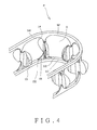
FIG. 4 shows that the chain of the present invention forms a curve;
FIG. 5 shows that the chain of the present invention is used in a slide assembly and passing through a turning portion of the slide assembly;
FIG. 6 shows a portion of the second embodiment of the chain of the present invention;
FIG. 7 shows a portion of the third embodiment of the chain of the present invention;
FIG. 8 shows a portion of the fourth embodiment of the chain of the present invention;
FIG. 9 is a cross sectional view taken along line B-B of FIG. 8;
FIG. 10 is a perspective view to show the conventional chain;
FIG. 11 shows that the conventional chain forms a curve, and
FIG. 12 shows that the conventional chain is used in a slide assembly and passing through a turning portion of the slide assembly.
DETAILED DESCRIPTION OF THE PREFERRED EMBODIMENT
Referring to FIG. 1, the chain “P” for rolling elements of the present invention comprises a flat carrier belt 1 which extends along the longitudinal direction “A” and has a first side strip 12 and a second side strip 13 on two sides thereof. Multiple holes 11 are defined in the carrier belt 1 along the longitudinal direction “A” and located between the first and second side strips 12, 13. The first and second side strips 12, 13 are located adjacent to the holes 11. Each hole 11 has a first opening end 111 and a second opening end 112, and multiple retainers 2 are connected to the carrier belt 1 and located alternatively with respect to the holes 11. Multiple first ribs 14 are connected between the first side strip 12 and the retainer 2, and each of the first ribs 14 is located adjacent the hole 11 corresponding thereto. Multiple second ribs 15 are connected between the second side strip 13 and the retainer 2, and each of the second ribs 15 is located adjacent the hole 11 corresponding thereto. Each of the first and second side strips 12, 13 has a thickness T1, and each of the first and second ribs 14, 15 has a thickness T2 which is smaller than T1. Preferably, thickness T1 is larger than 0.1 mm to easily manufacture the chain by way of injection molding, and the preferable ratio between T2/T1 is less than 50% for providing better flexibility of the chain “P”. As shown in FIG. 2, a first curved side 141 is formed on the first rib 14 and located adjacent to the hole 11 corresponding thereto. A second curved side 151 is formed on the second rib 15 and located adjacent to the hole 11 corresponding thereto. As shown in FIG. 3, the thickness T2 of each of the first ribs 14 increases from the first opening end 111 toward the second opening end 112 of the hole 11 corresponding thereto. The thickness T2 of each of the second ribs 15 increases from the second opening end 112 toward the first opening end 111 of the hole 11 corresponding thereto.
As shown in FIG. 4, the first rib 14 is connected between the first side strip 12 and the retainer 2, and the second rib 15 is connected to the second side strip 13 and the retainer 2. Wherein, the first and second ribs 14, 15 reinforce the connections between the first and second side strips 12, 13 and the retainers 2 so that the flat carrier belt 1 and chain have even flexibility and can form smooth curves. As shown in FIG. 5, the chain “P” having the balls 3 is installed in the circulating passage/loop-like track of the linear slide assembly 4. When the chain “p” with balls 3 passes through the turning portion 41 of the circulating passage, the flat carrier belt 1 forms a smooth curve in the turning portion 41. Therefore, the stability and smoothness of the chain “p” during the passing of the turning portion 41 are improved. Further, because of the reinforcement of the connections between the first and second side strips 12, 13 and the retainers 2, the chain “P” can bear higher load and move at higher speed than the conventional one in the linear slide assembly 4.
FIG. 6 shows the second embodiment, wherein the chain comprises a flat carrier belt 1A which has a first side strip 12A and a second side strip 13A on two sides thereof. Multiple holes 11A are defined in the carrier belt 1A and located between the first and second side strips 12A, 13A. The first and second side strips 12A, 13A are located adjacent to the holes 11A. Each hole 11A has a first opening end 111A and a second opening end 112A, and multiple retainers 2A are connected to the carrier belt 1A and located alternatively with respect to the holes 11A. Multiple first ribs 14A are connected between the first side strip 12A and the retainer 2A, and each of the first ribs 14A is located adjacent the hole 11A corresponding thereto. Multiple second ribs 15A are connected between the second side strip 13A and the retainer 2A, and each of the second ribs 15A is located adjacent the hole 11A corresponding thereto. The thickness of each of the first and second ribs 14A, 15A increases from the mediate portion of each of the first and second side strips 12A, 13A toward the first and second opening ends 111A, 112A of the hole 11A.
FIG. 7 shows the third embodiment, wherein the chain comprises a flat carrier belt 1B which has a first side strip 12B and a second side strip 13B on two sides thereof. Multiple holes 11B are defined in the carrier belt 1B and located between the first and second side strips 12B, 13B. The first and second side strips 12B, 13B are located adjacent to the holes 11B. Multiple retainers 2B are connected to the carrier belt 1B and located alternatively with respect to the holes 11B. Multiple first ribs 14B are connected between the first side strip 12B and the retainer 2B, and each of the first ribs 14B is located adjacent the hole 11B corresponding thereto. Multiple second ribs 15B are connected between the second side strip 13B and the retainer 2B, and each of the second ribs 15B is located adjacent the hole 11B corresponding thereto. A first straight side 141B is formed on the first rib 14B and located adjacent to the hole 11B corresponding thereto. A second straight side 151B is formed on the second rib 15B and located adjacent to the hole 11B corresponding thereto. The carrier belt 1B can generate smooth curves.
FIGS. 8 and 9 shows the fourth embodiment, wherein the chain comprises a flat carrier belt 1C which has a first side strip 12C and a second side strip 13C on two sides thereof. Multiple holes 11C are defined in the carrier belt 1C and located between the first and second side strips 12C, 13C. The first and second side strips 12C, 13C are located adjacent to the holes 11C. Multiple retainers 2C are connected to the carrier belt 1C and located alternatively with respect to the holes 11C. Multiple first ribs 14C are connected between the first side strip 12C and the retainer 2C, and each of the first ribs 14C is located adjacent the hole 11C corresponding thereto. Multiple second ribs 15C are connected between the second side strip 13C and the retainer 2C, and each of the second ribs 15C is located adjacent the hole 11C corresponding thereto. The thickness of each of the first ribs 14C increases from the retainer 2C connected to the first rib 14C toward the direction away from the retainer 2C. The thickness of each of the second ribs 15C increases from the retainer 2C connected to the second rib 15C toward the direction away from the retainer 2C. The carrier belt 1C therefore may have more even flexibility and can form smoother curves than the previous embodiments of the chain.
While we have shown and described the embodiment in accordance with the present invention, it should be clear to those skilled in the art that further embodiments may be made without departing from the scope of the present invention.

Claims (6)

What is claimed is:
1. A chain for rolling elements, comprising:
a flat carrier belt having a first side strip and a second side strip on two sides thereof, multiple holes defined in the carrier belt and located between the first and second side strips, each hole having a first opening end and a second opening end, multiple retainers connected to the carrier belt and located alternatively with respect to the holes, multiple first ribs connected between the first side strip and the retainer, each of the first ribs located adjacent the hole corresponding thereto, multiple second ribs connected between the second side strip and the retainer, each of the second ribs located adjacent the hole corresponding thereto, each of the first and second side strips having a thickness T1, and each of the first and second ribs having a thickness T2 which is smaller than T1, wherein the thickness of each of the first ribs increases from the first opening end toward the second opening end of the hole corresponding thereto, the thickness of each of the second ribs increases from the second opening end toward the first opening end of the hole corresponding thereto.
2. The chain as claimed in claim 1, wherein a straight side or a curved side is formed on the first and second ribs and located adjacent to the holes corresponding thereto.
3. The chain as claimed in claim 1, wherein the thickness of each of the first ribs increases from the retainer connected to the first rib toward a direction away from the retainer, the thickness of each of the second ribs increases from the retainer connected to the second rib toward a direction away from the retainer.
4. A chain for rolling elements, comprising:
a flat carrier belt having a first side strip and a second side strip on two sides thereof, multiple holes defined in the carrier belt and located between the first and second side strips, each hole having a first opening end and a second opening end, multiple retainers connected to the carrier belt and located alternatively with respect to the holes, multiple first ribs connected between the first side strip and the retainer, each of the first ribs located adjacent the hole corresponding thereto, multiple second ribs connected between the second side strip and the retainer, each of the second ribs located adjacent the hole corresponding thereto, each of the first and second side strips having a thickness T1, and each of the first and second ribs having a thickness T2 which is smaller than T1, wherein the thickness of each of the first and second ribs increases from a mediate portion of each of the first and second side strips toward the first and second opening ends of the hole.
5. The chain as claimed in claim 4, wherein a straight side or a curved side is formed on the first and second ribs and located adjacent to the holes corresponding thereto.
6. The chain as claimed in claim 4, wherein the thickness of each of the first ribs increases from the retainer connected to the first rib toward a direction away from the retainer, the thickness of each of the second ribs increases from the retainer connected to the second rib toward a direction away from the retainer.
US13/777,716 2012-09-03 2013-02-26 Chain for rolling elements Active 2033-04-04 US8887892B2 (en)

Applications Claiming Priority (3)

Application Number Priority Date Filing Date Title
TW101132005A TWI503490B (en) 2012-09-03 2012-09-03 Chain for rolling elements
TW101132005A 2012-09-03
TW101132005 2012-09-03

Publications (2)

Publication Number Publication Date
US20140060996A1 US20140060996A1 (en) 2014-03-06
US8887892B2 true US8887892B2 (en) 2014-11-18

Family

ID=50098566

Family Applications (1)

Application Number Title Priority Date Filing Date
US13/777,716 Active 2033-04-04 US8887892B2 (en) 2012-09-03 2013-02-26 Chain for rolling elements

Country Status (5)

Country Link
US (1) US8887892B2 (en)
JP (1) JP5716060B2 (en)
CN (1) CN103671550B (en)
DE (1) DE102013109241A1 (en)
TW (1) TWI503490B (en)

Families Citing this family (1)

* Cited by examiner, † Cited by third party
Publication number Priority date Publication date Assignee Title
US10690188B2 (en) * 2017-12-22 2020-06-23 Aktiebolaget Skf Flexible cage for rolling bearing

Citations (12)

* Cited by examiner, † Cited by third party
Publication number Priority date Publication date Assignee Title
US2665958A (en) * 1952-01-29 1954-01-12 Chefford Master Mfg Co Inc Ball retainer ring for ball bearings
US3486212A (en) * 1966-04-08 1969-12-30 Textron Inc Method of making a ball-bearing retainer
US5391126A (en) * 1992-08-05 1995-02-21 Nsk Ltd. Toroidal type continuously variable transmission
US6364086B1 (en) 1998-05-29 2002-04-02 Rexroth Star Gmbh Chain of rolling elements chain arrangement
US7150564B2 (en) * 2004-10-12 2006-12-19 Linear Tech Co., Ltd. Structure of linear sliding rail circulating device
US7419302B2 (en) * 2004-11-11 2008-09-02 Nsk Ltd. Linear guide device and rolling element accommodating belt for the same
US7465092B2 (en) * 2005-11-11 2008-12-16 Chieftech Precision Co., Ltd. Ball chain
US7563029B2 (en) * 2006-11-01 2009-07-21 Precision Motion Industries, Inc. Rolling element chain
US7802922B2 (en) * 2007-04-13 2010-09-28 Ome Technology Co., Ltd. Retaining structure for rolling elements
TW201122262A (en) 2009-12-25 2011-07-01 Chieftech Prec Co Ltd Ball retainer chain, its manufacturing method used by being integrated to the linear motion mechanism
US8408796B1 (en) * 2011-11-21 2013-04-02 Chieftech Precision Co., Ltd. Rolling element retainer belt and linear motion guide apparatus
US8414192B2 (en) * 2004-07-08 2013-04-09 Jtekt Corporation Cage for ball bearing

Family Cites Families (8)

* Cited by examiner, † Cited by third party
Publication number Priority date Publication date Assignee Title
JP4062574B2 (en) * 1999-09-07 2008-03-19 Thk株式会社 Manufacturing method of rolling element assembly
JP4365522B2 (en) * 2000-10-18 2009-11-18 日本トムソン株式会社 Linear motion guidance unit with separator connection
JP2007092898A (en) * 2005-09-29 2007-04-12 Nsk Ltd Rolling body accommodation belt for linear motion guide device and linear motion guide device
CN100484705C (en) * 2006-07-21 2009-05-06 银泰科技股份有限公司 Linear Slide Holder
CN201043568Y (en) * 2007-05-14 2008-04-02 精浚科技股份有限公司 Structure of rolling member retainer
CN101634337B (en) * 2008-07-23 2011-05-25 直得科技股份有限公司 Rolling element retaining chain unit
JP5908250B2 (en) * 2011-10-18 2016-04-26 直得科技股▲ふん▼有限公司 Rolling body holding chain capable of rotating operation and linear motion mechanism comprising the same
JP2013113359A (en) * 2011-11-28 2013-06-10 Jtekt Corp Retainer for roller bearing

Patent Citations (13)

* Cited by examiner, † Cited by third party
Publication number Priority date Publication date Assignee Title
US2665958A (en) * 1952-01-29 1954-01-12 Chefford Master Mfg Co Inc Ball retainer ring for ball bearings
US3486212A (en) * 1966-04-08 1969-12-30 Textron Inc Method of making a ball-bearing retainer
US5391126A (en) * 1992-08-05 1995-02-21 Nsk Ltd. Toroidal type continuously variable transmission
US6364086B1 (en) 1998-05-29 2002-04-02 Rexroth Star Gmbh Chain of rolling elements chain arrangement
US8414192B2 (en) * 2004-07-08 2013-04-09 Jtekt Corporation Cage for ball bearing
US7150564B2 (en) * 2004-10-12 2006-12-19 Linear Tech Co., Ltd. Structure of linear sliding rail circulating device
US7419302B2 (en) * 2004-11-11 2008-09-02 Nsk Ltd. Linear guide device and rolling element accommodating belt for the same
US7465092B2 (en) * 2005-11-11 2008-12-16 Chieftech Precision Co., Ltd. Ball chain
US7563029B2 (en) * 2006-11-01 2009-07-21 Precision Motion Industries, Inc. Rolling element chain
US7802922B2 (en) * 2007-04-13 2010-09-28 Ome Technology Co., Ltd. Retaining structure for rolling elements
TW201122262A (en) 2009-12-25 2011-07-01 Chieftech Prec Co Ltd Ball retainer chain, its manufacturing method used by being integrated to the linear motion mechanism
US8297843B2 (en) * 2009-12-25 2012-10-30 Chiefteck Precision Co., Ltd. Ball retainer chain, a method of making the same, and a linear guide apparatus
US8408796B1 (en) * 2011-11-21 2013-04-02 Chieftech Precision Co., Ltd. Rolling element retainer belt and linear motion guide apparatus

Also Published As

Publication number Publication date
CN103671550A (en) 2014-03-26
US20140060996A1 (en) 2014-03-06
JP2014047923A (en) 2014-03-17
CN103671550B (en) 2016-02-10
TWI503490B (en) 2015-10-11
JP5716060B2 (en) 2015-05-13
TW201411002A (en) 2014-03-16
DE102013109241A1 (en) 2014-03-06

Similar Documents

Publication Publication Date Title
US8104989B2 (en) Retaining structure
US7721874B2 (en) Roller chain for a linear guideway
RU2014121050A (en) TRACK TAPE
KR200469401Y1 (en) Linear sliding block having rolling ball retainer
US20130259409A1 (en) Linear sliding block
US20150204437A1 (en) Guide shoe
TWI582315B (en) Rolling element accommodating tool
CN108026966B (en) Linear motion guides, end caps for linear motion guides
US8887892B2 (en) Chain for rolling elements
US8408796B1 (en) Rolling element retainer belt and linear motion guide apparatus
US11771217B2 (en) Sliding table
US9297415B2 (en) Linear actuator
US10550886B2 (en) Nonmetallic bearing on bearing assembly
US7121723B2 (en) Linear guide apparatus
US7585112B2 (en) Linear motion guide apparatus
CN105121873B (en) Motion guide device
CN205823938U (en) Linear slide
CN204961574U (en) Linear slides with full dust protection
US20110023641A1 (en) Chain Type Transmission Assembly
US8888368B2 (en) Roller retaining chain
US7563029B2 (en) Rolling element chain
WO2009147260A3 (en) Lift guide
US9651113B2 (en) Silent chain
US20080110285A1 (en) Roller Screw System
CN201215163Y (en) Ball screw device

Legal Events

Date Code Title Description
AS Assignment

Owner name: CHIEFTEK PRECISION CO., LTD., TAIWAN

Free format text: ASSIGNMENT OF ASSIGNORS INTEREST;ASSIGNOR:HSU, MING-CHE;REEL/FRAME:029880/0419

Effective date: 20130219

STCF Information on status: patent grant

Free format text: PATENTED CASE

MAFP Maintenance fee payment

Free format text: PAYMENT OF MAINTENANCE FEE, 4TH YR, SMALL ENTITY (ORIGINAL EVENT CODE: M2551)

Year of fee payment: 4

MAFP Maintenance fee payment

Free format text: PAYMENT OF MAINTENANCE FEE, 8TH YR, SMALL ENTITY (ORIGINAL EVENT CODE: M2552); ENTITY STATUS OF PATENT OWNER: SMALL ENTITY

Year of fee payment: 8

MAFP Maintenance fee payment

Free format text: PAYMENT OF MAINTENANCE FEE, 12TH YR, SMALL ENTITY (ORIGINAL EVENT CODE: M2553); ENTITY STATUS OF PATENT OWNER: SMALL ENTITY

Year of fee payment: 12