US8887793B2 - Screen attachment method for lineals - Google Patents
Screen attachment method for lineals Download PDFInfo
- Publication number
- US8887793B2 US8887793B2 US13/724,289 US201213724289A US8887793B2 US 8887793 B2 US8887793 B2 US 8887793B2 US 201213724289 A US201213724289 A US 201213724289A US 8887793 B2 US8887793 B2 US 8887793B2
- Authority
- US
- United States
- Prior art keywords
- screen
- assembly
- latch
- lineal
- spring
- Prior art date
- Legal status (The legal status is an assumption and is not a legal conclusion. Google has not performed a legal analysis and makes no representation as to the accuracy of the status listed.)
- Expired - Fee Related, expires
Links
Images


Classifications
-
- E—FIXED CONSTRUCTIONS
- E06—DOORS, WINDOWS, SHUTTERS, OR ROLLER BLINDS IN GENERAL; LADDERS
- E06B—FIXED OR MOVABLE CLOSURES FOR OPENINGS IN BUILDINGS, VEHICLES, FENCES OR LIKE ENCLOSURES IN GENERAL, e.g. DOORS, WINDOWS, BLINDS, GATES
- E06B5/00—Doors, windows, or like closures for special purposes; Border constructions therefor
- E06B5/10—Doors, windows, or like closures for special purposes; Border constructions therefor for protection against air-raid or other war-like action; for other protective purposes
-
- E—FIXED CONSTRUCTIONS
- E06—DOORS, WINDOWS, SHUTTERS, OR ROLLER BLINDS IN GENERAL; LADDERS
- E06B—FIXED OR MOVABLE CLOSURES FOR OPENINGS IN BUILDINGS, VEHICLES, FENCES OR LIKE ENCLOSURES IN GENERAL, e.g. DOORS, WINDOWS, BLINDS, GATES
- E06B3/00—Window sashes, door leaves, or like elements for closing wall or like openings; Layout of fixed or moving closures, e.g. windows in wall or like openings; Features of rigidly-mounted outer frames relating to the mounting of wing frames
- E06B3/04—Wing frames not characterised by the manner of movement
- E06B3/26—Compound frames, i.e. one frame within or behind another
-
- E—FIXED CONSTRUCTIONS
- E06—DOORS, WINDOWS, SHUTTERS, OR ROLLER BLINDS IN GENERAL; LADDERS
- E06B—FIXED OR MOVABLE CLOSURES FOR OPENINGS IN BUILDINGS, VEHICLES, FENCES OR LIKE ENCLOSURES IN GENERAL, e.g. DOORS, WINDOWS, BLINDS, GATES
- E06B9/00—Screening or protective devices for wall or similar openings, with or without operating or securing mechanisms; Closures of similar construction
- E06B9/01—Grilles fixed to walls, doors, or windows; Grilles moving with doors or windows; Walls formed as grilles, e.g. claustra
-
- E—FIXED CONSTRUCTIONS
- E06—DOORS, WINDOWS, SHUTTERS, OR ROLLER BLINDS IN GENERAL; LADDERS
- E06B—FIXED OR MOVABLE CLOSURES FOR OPENINGS IN BUILDINGS, VEHICLES, FENCES OR LIKE ENCLOSURES IN GENERAL, e.g. DOORS, WINDOWS, BLINDS, GATES
- E06B9/00—Screening or protective devices for wall or similar openings, with or without operating or securing mechanisms; Closures of similar construction
- E06B9/52—Devices affording protection against insects, e.g. fly screens; Mesh windows for other purposes
- E06B2009/527—Mounting of screens to window or door
-
- Y—GENERAL TAGGING OF NEW TECHNOLOGICAL DEVELOPMENTS; GENERAL TAGGING OF CROSS-SECTIONAL TECHNOLOGIES SPANNING OVER SEVERAL SECTIONS OF THE IPC; TECHNICAL SUBJECTS COVERED BY FORMER USPC CROSS-REFERENCE ART COLLECTIONS [XRACs] AND DIGESTS
- Y10—TECHNICAL SUBJECTS COVERED BY FORMER USPC
- Y10T—TECHNICAL SUBJECTS COVERED BY FORMER US CLASSIFICATION
- Y10T292/00—Closure fasteners
- Y10T292/08—Bolts
- Y10T292/096—Sliding
- Y10T292/0969—Spring projected
Definitions
- the present invention relates generally to the field of window screen latch mechanisms and, more particularly, to spring-biased screen latch.
- Screen latches are used to secure a screen to a window frame so that the screen may be installed and removed depending on the season and desired use by an occupant.
- a window screen assembly includes a screen frame and a spring biased latch assembly.
- the screen frame includes at least one lineal member having a screen channel and at least one aperture positioned between a first end and a second end of the lineal member.
- the screen member is secured in the screen channel.
- the spring biased latch assembly is located within the aperture and includes a latch portion biased in a direction away from the screen channel
- FIG. 1 is an isometric partial view of a latch mechanism.
- FIG. 1A is a cross-sectional view of the latch mechanism taken generally about line 1 A- 1 A of FIG. 1 .
- FIG. 2 is a cross-sectional view of the latch mechanism of FIG. 1 in an engaged position taken along lines 2 - 2 of FIG. 1 .
- FIG. 3 is a cross-sectional view of the latch mechanism of FIG. 2 in a disengaged position.
- FIG. 4 is a cross-sectional view of the latch mechanism of FIG. 2 in a locked position.
- FIG. 5 is a cross-sectional view of the latch mechanism of FIG. 2 in a rocked position.
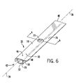
- FIG. 6 is an isometric view of a lineal component of the latch mechanism of FIG. 1 .
- FIG. 7 is a cross-sectional view of the lineal component of FIG. 6 taken along lines 7 - 7 of FIG. 6 .
- FIG. 8 is a side view of a latch component of the latch mechanism of FIG. 1 .
- FIG. 9 is an isometric partially-exploded view of the lineal component of FIG. 6 and the latch component of FIG. 8 positioned relative to one another prior to coupling.
- FIG. 10 is an end view of the lineal component of FIG. 6 coupled to the latch component of FIG. 8 .
- FIG. 11 is an isometric view of the lineal component of FIG. 6 coupled to the latch component of FIG. 8 .
- FIG. 12 is a cross-sectional view of an architectural frame component of the latch of FIG. 1 taken along lines 12 - 12 of FIG. 1 .
- FIG. 13 is a top angle view of the total latch assembly aligning for insertion into a screen lineal.
- FIG. 14 is a side view of a screen lineal.
- FIG. 15 is a side view of a shield installed with a slide aligned to be installed.
- FIG. 16 is an exploded rear view of the latch assembly.
- FIG. 17 is a top angled view of a shield installed with a slide aligned to be installed.
- FIG. 18 is a side view of the screen frame and latch assembly prior to being engaged with a window frame.
- FIG. 19 is a side view of the screen frame and latch assembly engaged with a window frame.
- a latch mechanism 10 is configured to removably secure a screen assembly 12 to an architectural frame 14 such as a window frame or door frame.
- Screen assembly 12 comprises a flexible membrane or screen 16 attached to a screen frame 18 with an attachment device or spline 20 .
- Screen frame 18 includes a screen frame member or lineal 22 .
- Screen assembly 12 when secured to architectural frame 14 separates the inside of a building with the outside of the building, or separates one part of an architectural structure from another part of the architectural structure.
- At least one latch mechanism 10 is coupled to lineal 22 to removably secure screen assembly 12 to architectural frame 14 .
- Latch mechanism 10 may be used to secure a screen to a window or door.
- a window or door with a screen is installed in a vertically-oriented, exterior wall of a building structure separating an inside space from an outside space.
- latch mechanism 10 may be used to secure a screen assembly to different types of windows and doors and in different locations and orientations on the structure, latch mechanism 10 will be described relative to a screen assembly secured to a window in an exterior wall of a structure with the screen assembly 12 being secured to the frame from the inside of the structure.
- the direction “up” or “upward” is used to reference a general vertically-oriented vector direction away from the force of gravity while the term “down” or “downward” is used to reference a general vertically-oriented vector direction toward the force of gravity.
- the direction “in” or “inward” is used to reference a general horizontally-oriented vector direction toward the inside of the structure.
- the direction “out” or “outward” is used to reference a general horizontally-oriented vector direction toward the outside of the structure.
- the term “front” or “inside” is used to describe the surface that a person would see facing the window from the inside of a building structure while the term “rear” or “outside” is used to describe the surface that a person would see facing the window from the outside of a building structure.
- the term “inboard” is used to describe the area inside the form or shape created by architectural frame 14
- the term “outboard” is used to describe the area outside the form created by architectural frame 14 . “Inboardly” and “outboardly” define directions moving toward the inboard area or toward the outboard area, respectively
- latch mechanism 10 includes a bolt or latch member 24 and a handle 26 that are movably coupled to lineal 22 in a sliding motion along a vector direction 28 between an engaged position and a disengaged position with respect to architectural frame 14 .
- the term vector 28 will include a line in both directions.
- a plurality of latch mechanisms 10 are located about screen assembly 12 .
- Latch mechanism may be rocked to a locked position when latch mechanism 10 is in the disengaged position to maintain latch mechanism 10 in the disengaged position when a user releases handle 26 .
- latch mechanism 10 may be rocked to an unlocked position to allow latch mechanism 10 to move to the engaged position.
- Latch mechanism 10 provides easy operation for removably securing screen assembly 12 to architectural frame 14 .
- Screen assembly 12 is secured or attached to architectural frame 14 from inside the structure with handle 26 also facing inside the structure and facing a user.
- handle 26 To attach screen assembly 12 to architectural frame 14 , a user positions screen assembly 12 into alignment with the corresponding opening in architectural frame 14 and exerts a force on screen lineal members 22 toward architectural frame 14 in the outside direction.
- the position of handle 26 automatically adjusts as latch member 24 engages architectural frame 14 .
- handle 26 of latch mechanism 10 responds to the force of the screen being pressed into architectural frame 14 by sliding along vector 28 generally inboardly within lineal 22 as latch member 24 engages architectural frame 14 , and then moves outboardly once latch member 24 clears architectural frame 14 .
- Handle 26 ceases movement in the engaged position, correlating to completion of attachment of screen assembly 12 to architectural frame 14 .
- the user manipulates handle 26 . First, the user slides handle 26 inboardly to the disengaged position. Secondly, the user rocks handle 26 about an axis 34 substantially parallel to or co-linear with a longitudinal axis 44 of lineal 22 . As a result latch mechanism is pivoted to the locked position.
- latch mechanism 10 With latch member 24 in the locked position, the user ceases manipulation of handle 26 and removes screen assembly 12 from architectural frame 14 .
- Latch mechanism 10 will remain in the locked position until the user manipulates handle 26 by rocking handle 26 to the unlocked position thereby releasing latch mechanism 10 from the locked position.
- the user Prior to reattachment of screen assembly 12 to architectural frame 14 , the user preferably releases latch mechanism 10 from locked position by rocking handle 26 in the opposing direction that the handle was rocked to lock the latch mechanism, thereby pivoting latch mechanism 24 in the opposing direction about axis 34 to the unlocked position.
- latch member 24 and handle 26 is spring biased to the extended engaged position in preparation for reattachment of screen assembly 12 to architectural frame 14 .
- the user may alternatively unlock latch mechanism 10 after positioning screen assembly 12 into alignment with architectural frame 14 .
- flexible membrane or screen 16 provides a separation between two areas, including between two rooms or areas within a building structure and between the inside of a building structure and the outside of the building structure.
- Screen 16 may be constructed of a material with characteristics including, but not limited to, the following: permeable, impermeable, metallic, plastic, fabric, opaque, translucent, transparent, woven. Screen 16 may also include decorative elements including, but not limited to, designs and artwork.
- screen 16 may be of a permeable material and located in an exterior building wall, thereby allowing air circulation between the inside and outside of the building.
- screen 16 may be of a permeable material and located in an interior building wall, thereby allowing air circulation between two rooms within a building.
- screen 16 may be of a translucent material with an included artistic design, thereby providing visual and aesthetically-pleasing privacy between two rooms within a building.
- Screen frame 18 is a substantially rigid component or structure, including at least one lineal 22 , configured to receive and support screen 16 and to interface with architectural frame 14 .
- Screen frame 18 has a shape corresponding to the shape of architectural frame 14 and a configuration to accept screen 16 and spline 20 such that screen 16 spans the area contained within the shape or inboard area of screen frame 18 .
- screen frame 18 may include four lineals, creating a rectangular or square shape.
- screen frame 18 may include three lineals, creating a triangular shape.
- screen frame 18 may include other quantities of lineal 22 , creating other shapes, including, but not limited to, pentagon, hexagon and octagon.
- Spline 20 comprises a component of compressible material of a substantially consistent cross-sectional area and of a length sufficient to circumnavigate the perimeter of the shape of screen frame 18 proximate the inboard area.
- Spline 20 retains screen 16 to screen frame 18 by compressive fitment of spline 20 into an area of screen frame 18 with a cross-sectional area that is smaller than the cross-section of spline 20 .
- Spline 20 and screen 16 are removable from frame 18 substantially without damage to spline 20 , screen 16 or frame 18 .
- screen member or lineal portion or lineal 22 is a substantially rigid component of screen frame 18 configured to removably secure latch mechanism 10 and to engage with architectural frame 14 .
- Lineal 22 includes a first end 40 , a second end 42 and a longitudinal axis 36 extending between first end 40 and second end 42 .
- Lineal 22 comprises members that extend between first end 40 and second end 42 including a first wall 46 , the first wall 46 includes a first or interior surface 48 and a second opposing front or exterior surface 50 ; a second wall 52 spaced from and parallel to first wall 46 .
- Second wall 52 includes a first or interior surface 54 and a second or exterior surface 56 ; a third wall 58 , includes a first or interior surface 60 and a second or exterior surface 62 .
- a fourth wall 64 is spaced from and parallel to third wall 58 , the fourth wall 64 includes a first or interior surface 66 and a second or exterior surface 68 .
- Third wall 58 and fourth wall 64 extend generally perpendicular to first wall 46 and second wall 52 .
- a cavity 70 is formed by the first wall 46 , second wall 52 , third wall 58 and fourth wall 64 .
- a first opening 72 extends through first wall 46 and a second opening 74 extends through third wall 58 proximate to first opening 72 .
- First opening 72 and second opening 74 are located intermediate first end 40 and second end 42 .
- first opening 72 and second opening 74 each comprise a circular opening formed from a standard drill bit.
- at least one of first opening 72 and second opening 74 may be noncircular or may be formed by an alternate machining method.
- Lineal 22 also includes a flange or lineal extension 76 extending from first wall 46 .
- Lineal extension 76 includes a first side 138 proximate third wall 58 and an opposing second side 140 distal third wall 58 .
- lineal extension 76 is substantially coplanar with first wall 46 .
- lineal extension 76 may be located in a plane spaced from and substantially parallel to first wall 46 .
- a spline flange 78 extends from first wall 46 and is substantially perpendicular to first wall 46 .
- Spline flange 78 is spaced from and substantially parallel to fourth wall 64 .
- a spline groove 80 is formed between spline flange 78 and fourth wall 64 .
- Spline groove 80 is configured to receive a peripheral portion of screen 16 and spline 20 .
- Spline groove 80 is external to cavity 70 and distal first opening 72 , second opening 74 , and lineal extension 76 .
- a retaining groove or retaining channel 82 is extends from cavity 70 and is formed by first wall 46 and a fifth wall 84 extending between fourth wall 64 and spline flange 78 .
- latch mechanism 10 is configured to be removably coupled to lineal 22 and to engage with architectural frame 14 .
- Latch mechanism 10 includes latch member 24 , handle 26 , and a retaining portion 86 .
- Retaining portion 86 is intermediate latch member 24 and handle 26 .
- a Spring member or spring 88 extends from latch member 24 .
- the latch member 24 , handle 26 , and retaining portion 86 are secured together in a fixed arrangement.
- latch member 24 , handle 26 , and retaining portion 86 comprise a unitary body of solid material.
- latch member 24 , handle 26 , and retaining portion 86 may be individual components permanently secured to one another.
- latch member 24 , handle 26 , and retaining portion 86 may be constructed of nonsolid material. In one embodiment, one or more of latch member 24 , handle 26 , and retaining portion 86 may be constructed of a resilient material including, but not limited to, a polymer material.
- Handle 26 is a component configured for manipulation by a user to create movement in vector direction 28 and about rocking axis 34 .
- Handle 26 includes a first end or spring end 90 and a second end or engagement end 92 and a thumbrest surface 94 intermediate first end 90 and an opposing second end 92 .
- surface 94 may be concave or recessed relative to ends 90 and 92 .
- surface 94 may have another shape relative to ends 90 and 92 , the shape including, but not limited to, flat.
- Latch member 24 is a component configured to engage with architectural frame 14 .
- Latch member 24 is dimensionally configured to fit substantially within cavity 70 .
- Latch member 24 comprises a first side or engagement region 96 , the engagement region 96 includes a beveled surface or ramp 98 terminating at a nose 102 , a horizontal surface 103 extends from nose 102 to a substantially vertical catch surface 100 .
- Horizontal surface 103 and vertical catch surface 100 form a notch 105 .
- Catch surface 100 terminates at an upper end with a substantially horizontal surface 104 .
- Latch member 24 also includes a second side or spring wall 106 .
- Engagement region 96 and spring wall 106 are configured on opposing sides of latch member 24 in a fixed arrangement. Movement of spring wall 106 results in correlating movement of engagement region 96 .
- Retaining portion 86 is configured in combination with latch member 24 and handle 26 to retain latch mechanism 10 in a given position relative to lineal 22 .
- Retaining portion 86 comprises a first end or retaining member 108 adjacent extending from spring wall 106 in a direction away from engagement region 96 .
- a guide groove 110 is formed between a bottom of handle 26 and retaining member 108 .
- Retaining member 108 includes an upper surface 112 facing handle 26 and an opposing bottom surface 114 .
- Retaining portion 86 further includes a retaining flange 116 extending from the bottom of handle 26 .
- Retaining flange 116 includes an engagement surface 118 extending from the bottom of handle 26 to the bottom of retaining flange 116 .
- Engagement surface 118 may be perpendicular to the bottom of handle 26 or may form an angle with respect the bottom of handle 26 forming a lock notch 119 .
- a groove 120 is formed between the bottom of retaining flange 116 and upper surface 104 of latch member 24 .
- Spring member 88 is a component configured to bias latch mechanism 10 in vector direction 28 into engagement with architectural frame 14 .
- Spring 88 is attached to spring region 106 .
- Spring region 106 may include a bore or other fastening mechanism to secure or locate spring 88 to latch member 24 .
- the spring 88 extends substantially perpendicular from surface 106 .
- spring 88 is a compression spring that creates a force against surface 106 when spring 88 is compressed, resulting in a biasing force of latch member 24 in a vector direction 28 from spring region 106 toward engagement region 96 .
- latch member 24 is removably coupled to lineal 22 intermediate first end 40 and second end 42 .
- latch member 24 is positioned relative to lineal 22 in preparation for coupling.
- latch member 24 is coupled to lineal 22 .
- latch mechanism 10 is oriented above first opening 72 with latch member 24 proximate first opening 72 , with nose 102 pointing toward lineal extension 76 and with spring 88 pointing toward spline groove 80 .
- Manipulation of latch mechanism 10 during coupling occurs substantially by manipulation of handle 26 , wherein latch member 24 is inserted into cavity 70 through first opening 72 .
- engagement region 96 engages second opening 74
- groove 120 receives a portion of lineal extension 76
- retaining groove 110 receives a portion of wall 46 of lineal 22 .
- Spring 88 contacts and/or engages interior surface 66 of fourth wall 64 .
- spring 88 is compressed by contact with fourth wall 64 , thereby biasing engagement region 96 through second opening 74 until contact between wall 122 of groove 120 and lineal extension 76 prevents further movement.
- latch mechanism 10 is tilted or twisted to point the free end of spring 88 toward first opening 72 , followed by twisting of latch mechanism 10 in rotating motion about an axis that is generally parallel to the longitudinal axis 36 of lineal 22 .
- engagement region 96 extends through second opening 74 and lip groove 120 receives a portion of lineal extension 76 .
- latch mechanism 10 may be twisted or rotated to point the free end of spring 88 generally toward one of lineal first end 40 and lineal second end 42 , followed by twisting of latch mechanism 10 to allow engagement region 96 to extend through second opening 74 and lip groove 120 receives lineal extension 76 .
- latch mechanism 10 In yet another embodiment of coupling latch mechanism 10 with lineal 22 a combination of twisting motions may occur. A first twisting motion as latch assembly is inserted through first opening 72 and followed by a second different twisting motion to insert engagement region 96 through second opening 74 . In still another embodiment, latch mechanism is coupled to lineal 22 before screen 16 and spline 20 are received in spline groove 80 .
- handle first end 90 does not extend beyond spline flange 78 and handle second end 92 does not extend beyond a terminal edge of lineal extension 76 .
- architectural frame 14 such as a window frame or door frame provides a structure to which screen assembly 12 is removably secured.
- Architectural frame 14 comprises a wall 124 including a first surface 126 and a second opposing surface 128 .
- Second surface 128 is substantially parallel to first surface 126 .
- Architectural frame 14 includes a third surface 130 , the third surface 128 substantially perpendicular first surface 126 and second surface 128 .
- a frame lip 132 extends from the interface of wall 124 and third surface 130 .
- lip 132 is substantially coplanar with wall 124 and substantially perpendicular to third surface 130 .
- lip 132 may be spaced from and substantially parallel to wall 124 .
- screen assembly 12 is removably secured to architectural frame 14 .
- screen assembly 12 is positioned relative to architectural frame 14 with lineal extension 76 proximate frame wall 124 with first side 138 of lineal extension 76 facing first surface 126 of wall 124 .
- Latch mechanism 10 is located within lineal 22 in the extended unlocked position. In this orientation, ramp 98 of latch member 24 abuts a first surface 134 of lip 132 . As a user exerts a force against screen assembly 12 generally toward architectural frame 14 to create movement of lineal extension 76 toward frame wall 124 , latch member 24 is forced inwardly into lineal 22 in vector direction 28 thereby compressing spring 88 . Retaining portion 86 and handle 26 correspondingly move with latch member 24 in vector direction 28 with handle 26 sliding along vector direction 28 away from lineal extension 76 . Latch member 24 will continue to travel toward wall 64 of lineal 22 until nose 102 of ramp 98 clears the free end of lip 132 .
- nose 102 extends a distance beyond the free edge of lip 132 toward wall 130 of architectural frame 14 .
- This overlap provides for both a secure latch of screen assembly 12 to architectural frame 14 .
- wall 122 of groove 120 extends an adjustment distance beyond wall 58 of lineal 22 .
- This distance allows for variability in the gap between screen assembly 12 and architectural frame 14 when screen assembly 12 is secured to architectural frame 14 .
- the adjustment distance or range is defined as the distance between surface 62 of third wall 58 of lineal 22 and wall 130 of frame 14 . This adjustment range varies relative to dimensional differences between screen assembly 12 and architectural frame 14 and provides a range of adjustment for positioning of screen assembly 12 relative to architectural frame 14 .
- two or more latch mechanisms 10 are secured to opposite vertical lineals 22 .
- spring 88 of each of the latch mechanisms will assist in centering screen assembly 12 within architectural frame 14 between the two vertical members of architectural frame 14 .
- two or more latch mechanisms may be secured to opposite horizontal lineals. In this embodiment, springs 88 of each of the opposing latch mechanisms in the horizontal lineals will assist in centering screen assembly 12 in the vertical direction.
- screen assembly 12 comprises a quantity of lineals 22 , the quantity of lineals 22 including, but not limited to, four and a quantity of latch mechanisms 10 , the quantity of latch mechanisms 10 including, but not limited to, four.
- the quantity of lineals 22 are configured to form a screen frame 18 of a shape including, but not limited to, a rectangle with one or more latch mechanisms 10 being coupled to each lineal 22 . Opposing forces exerted by latch mechanisms 10 substantially center screen assembly 12 relative to architectural frame 14 .
- screen assembly 12 is secured to architectural frame 14 in an engaged position.
- external force is exerted on handle 26 in vector direction 28 away from architectural frame 14 toward screen 16 moving handle 26 and latch member 24 inboardly and compressing spring 88 until spring wall 106 moves toward lineal fourth wall 64 and latch member 24 is disengaged from frame 14 .
- latch member 24 is in the disengaged position and no longer in contact with lip 132 of architectural frame 14 .
- lock refers to fixing the position of the latch mechanism 10 in a disengaged position with respect to lineal 22 such that latch member 24 will not engage architectural frame 14 when screen assembly 12 is pressed against architectural frame 14 .
- latch mechanism may be moved to a locked position once catch surface 100 moves through second opening 74 . Once catch surface 100 moves through second opening toward wall 64 , latch mechanism 10 may be rocked to a locked position.
- latch mechanism 10 rocks or rotates about its axis 34 until latch catch surface 100 catches or engages lineal third wall 58 intermediate lineal first wall 46 and lineal second opening 74 .
- latch retaining member 108 In the locked position, latch retaining member 108 is located within lineal retaining groove 82 and latch catch surface 100 proximate nose 102 is engaged with a peripheral portion of second opening 74 .
- Force exerted by spring 88 maintains contact between catch surface 100 and third wall 58 , thereby maintaining latch mechanism 10 in the locked position.
- spring 88 contacts wall 106 biasing latch member 24 about axis 34 such that first end 90 of handle 26 is closer to wall 46 than second end 92 of handle 26 .
- latch mechanism 10 To unlock latch mechanism 10 , to allow latch mechanism to extend to an engaged position, an external force is exerted on handle second end 92 toward lineal extension 76 , as a result, latch mechanism rocks about pivot axis 34 in a second direction opposite to the first direction when latch mechanism was rocked to the locked position. Referring to FIG. 5 , as latch mechanism rocks about pivot axis in the second direction latch notch surface 100 disengages lineal third wall 58 and extends through second opening 74 . As the external force applied by a user on handle 26 is released, the force exerted by spring 88 moves latch member 24 outboardly in vector direction 28 , such that latch member 98 extends through second opening 74 . In this unlocked orientation, screen assembly 12 may be secured to architectural frame 14 as discussed above.
- latch member 24 moves directly to the engaged position when latch mechanism is unlocked thereby securing screen assembly 12 to architectural frame 14 , without the need to engage ramp or beveled surface or ramp 98 against lip 132 of architectural frame 14 .
- screen assembly 12 is positioned to architectural frame 14 prior to release of latch mechanism 10 from the disengaged and locked position. In this position once lineal extension 76 contacts surface 126 of frame wall 124 a user may release the latch mechanism as discussed above. The force of spring 88 will move latch member 24 outboardly in vector direction 28 until reaching the engaged position.
- latch mechanism 10 may be rocked to a lock position by rotating latch mechanism 10 about axis 34 is a second direction opposite the first direction.
- engagement surface 118 engages a peripheral edge of first opening 72 .
- the handle 26 is rocked in the first direction to release engagement surface 118 from the first opening 72 , allowing the latch member 24 to extend through the second opening 74 by spring 88 .
- FIG. 13 another embodiment of a latch assembly 200 is used with a screen assembly including a plurality of screen lineal members 202 .
- Screen lineal members 202 forms the border a four sided screen frame 204 .
- a screen frame may be formed with any number of sides.
- Screen lineal 202 includes at least one top aperture 206 through which latch assembly is inserted thorough.
- Top aperture 206 may be predrilled at a factory or a user may drill the top aperture 206 in the field when the screen frame 204 is being assembled. As discussed below, any resulting burrs adjacent aperture 206 will be covered.
- top aperture 206 is approximately 3 ⁇ 8 of an inch in diameter; however other aperture diameters are also contemplated.
- each screen lineal 202 includes a plurality of walls that form a tunnel 208 and a channel 210 .
- Lineal 202 may be an extruded member having terminal ends that may be open at both ends, closed at either end or closed at both ends.
- Screen lineal 202 includes a flat top surface 212 that faces away from a window that is covered by the screen assembly. The flat top surface 212 is substantially parallel with a screen member 16 .
- aperture 206 is located on aperture 206 may be positioned between the terminal ends of lineal 202 . For example, with one aperture 206 located on each lineal 202 per side, the top aperture 206 is placed in the center position between the two terminal ends of lineal 202 . If there were two apertures 206 per lineal member 202 , the apertures 206 could be positioned at the one third and two thirds mark respectively from one terminal end of lineal 202 .
- Inclined surface 218 extends from top surface 212 in a direction towards a plane created by screen member 16 .
- the angle formed between flat top surface 212 and inclined surface 218 is approximately 150°, of course other angles are contemplated.
- Inclined surface 218 is connected to a lip surface 220 that is essentially parallel to the flat top surface 212 and the screen member 16 .
- the angle formed by the lip surface 220 and inclined surface is approximately 30°.
- Lip surface 220 is connected to a first vertical wall 222 extending in a direction away from top surface 212 .
- the angle formed between lip surface 220 and the first vertical wall 222 is 90°.
- the first vertical wall 222 has a side aperture 224 formed therethrough that lines up with the top aperture 206 .
- a bottom floor member 226 is connected to the first vertical wall 222 and extends nearly parallel to top surface 212 and screen member 16 .
- the angled created by the floor member 226 and first vertical wall 222 is approximately 90°.
- Floor 226 is connected to a second vertical wall 228 .
- the angle created by floor 226 and second vertical wall 228 is approximately 90°.
- Second vertical wall is substantially parallel to first vertical wall 222 .
- Second vertical wall 228 is connected to an elevated floor wall 230 .
- the elevated floor wall 230 is parallel to the tunnel floor 226 , approximately 1 ⁇ 2 the distance between floor 226 and top surface 212 .
- the elevated floor wall 230 extends perpendicular to floor 226 .
- the elevated floor wall 230 is connected to a third vertical wall 232 .
- the third vertical wall 232 extends 90° from elevated floor wall 230 towards flat top surface 212 .
- the third vertical wall 232 and the flat top surface 212 are connected at an edge 214 of top surface 212 and form a 90° angle.
- Channel 210 is defined by second vertical wall 228 , elevated floor wall 230 and third vertical wall 232 and includes an opening through which an edge of screen member 16 is secured.
- a pliable member or screen spline 240 is located within channel securing screen member 16 within the channel 210 .
- Channel 210 comprises the second vertical wall 228 connected to a channel top surface 236 at approximately 90°.
- the channel top surface 236 is connected to a third vertical wall 238 at approximately 90°.
- Within the channel 210 there is a rectangular block or screen spline 240 .
- the screen spline 240 is approximately the height the second vertical wall 228 and the third vertical wall 238 .
- Shield 248 is mounted on the flat top surface 212 of the screen lineal 202 .
- Shield 248 includes a horizontal panel 250 , a vertical panel 252 and a half cylinder backstop 254 .
- Horizontal panel 250 and the vertical panel 252 form an L-shape member.
- Extending from horizontal panel 250 in a direction away from a top surface of horizontal panel is a triangular portion 256 that mates with the slope portion of inclined surface 218 .
- the horizontal panel 250 comprises a first edge 258 that is adjacent to vertical panel 252 and is parallel to the longitudinal axis of screen lineal member 202 .
- Horizontal panel 250 includes a second edge 260 that is perpendicular to first edge 258 .
- a third edge 262 extends from second edge toward a fourth edge 266 that is parallel to second edge 260 and perpendicular to first edge 258 .
- third edge 262 has an concave arcuate shape where tangent of a center point 264 of curved third edge 262 is parallel to first edge 258 .
- horizontal panel 250 includes three apertures, two of which have a bottom forming a first cavity 268 and the second cavity 270 both of which are rectangular, at a length to width ratio of approximately 5:1.
- a first edge 272 of the first cavity 268 is proximate third edge 262 .
- a width edge 274 of the cavity 268 is proximate first edge 258 .
- a first length edge 276 of second cavity 270 is proximate second edge 260 .
- a width edge 278 of second cavity 270 is proximate the first edge 258 .
- a third aperture 280 of shield 248 is mushroom shaped with a first arcuate or mushroom head portion and a second stem or generally rectangular portion. Both the arcuate portion and the second portion are located between first channels 266 and second channel 270 .
- the imaginary line of the mirror center 272 of the mushroom shaped aperture 280 crosses the center point 264 of the third edge 262 of the horizontal panel 250 of shield 248 .
- the half cylinder backstop 254 extends through third aperture 280 .
- Half cylinder backstop 254 is extends downward beyond a bottom side 282 of horizontal panel 250 .
- On the vertical wall 288 of the half cylinder backstop 254 is a V-shaped guidepost 290 .
- the V-shaped guidepost 290 is used to mount a top slide 292 .
- a spring 294 is located within first channel 268 and a second spring 294 is located within second channel.
- the two springs 294 provide for the extension of top slide 292 away from screen member 16 .
- top slide 292 includes a cap 300 , a pair of spring bosses 302 , a vertical shaft 304 , and a latch 306 .
- Latch 306 includes a beveled surface 306 and a front stop 308 .
- cap 300 comprises three standard equilateral triangles 310 and an equilateral triangle with a curved side 312 that is not an equilateral side.
- the physical shape of cap 300 may be of any shape, preferably a design that is comfortable for a user's finger and/or hand.
- the pair of spring bosses 302 is mounted underneath the four sided pyramid cap 300 . Each spring boss 302 is configured to engage one end of a respective spring 294 .
- a vertical shaft 304 is center mounted on the bottom side 314 of the four sided pyramid cap 300 .
- Latch 306 is connected to the bottom side 316 of the vertical shaft 304 .
- Latch portion 320 points towards the window frame 322 and away from the screen frame 16 .
- front stop 308 has an arcuate shape that matched the arcuate opening of center aperture 280 .
- the attachment of the top slide 292 to shield 248 comprises orienting right latch 306 towards aperture 280 of horizontal panel 250 .
- Latch 306 and the vertical shaft 304 are inserted into aperture 280 such that the latch 320 points towards the window frame 322 and away from the screen 16 .
- the combination of the top slide 292 and the shield 248 comprise the latch assembly 200 .
- the resulting latch assembly 200 is shown in FIG. 17 . In operation vertical shaft 304 moves within the rectangular portion of center aperture 280 , while front stop 308 moves under shield 248 .
- the bottom side 314 of top slide 292 may contain two ribs 328 . These ribs 328 are designed to fit into the two pits 268 , 270 to hold springs 294 in place.
- snap-fit or snap-fitting is defined as:
- Replacing or inserting a screen frame 204 is a relatively simple process. If the latch assembly 200 is not already in place, there are three ways to attach the latch assembly 200 .
- the first method a user may simple purchase a latch assembly 200 already assembled. The user would snap-fit the latch assembly 200 into each aperture(s) 206 of the screen lineal(s) 204 .
- a second method a user may snap-fit a top slide 292 with a shield 248 and then snap-fit this assembly 200 into the aperture(s) 206 of the screen lineal(s) 204 .
- a third method would be to insert or snap-fit the shield 248 into the aperture(s) 206 of the screen lineal(s) 204 . Then, a user may snap-fit the top slide 292 into the shield 248 .
- latch assembly 200 when latch assembly 200 is located in top aperture 206 , vertical panel 252 rests on top of a screen side lip 330 .
- the horizontal panel 250 rests on the top surface 212 of lineal 202 .
- a user slides top slide 292 towards the screen 16 . This action moves the latch through side aperture 224 of lineal 202 , away from a window frame lip 326 .
- the screen frame 204 automatically releases the window frame. At this point, the screen 332 can be replaced.
- the window frame lip 326 interacts with the pointed end 320 of the right angle latch 306 .
- the latch 306 in one embodiment is formed from a right angle trapezoid blade moves back through side aperture 224 , toward and making contact with the window frame lip 326 .
- the force exerted on the right angle trapezoid blade 306 from the screen frame 204 insertion in combination with springs 294 forces the top slide 292 to slide back into closed or locked position. Springs 294 also counteract any loosening forces due to vibration or window operation.
Landscapes
- Engineering & Computer Science (AREA)
- Structural Engineering (AREA)
- Civil Engineering (AREA)
- Architecture (AREA)
- Life Sciences & Earth Sciences (AREA)
- Insects & Arthropods (AREA)
- Pest Control & Pesticides (AREA)
- Specific Sealing Or Ventilating Devices For Doors And Windows (AREA)
Abstract
Description
-
- A mechanical joint system where part-to-part attachment is accomplished with locating and locking features (constraint features) that are homogenous with one or the other of the components being joined. Joining requires the (flexible) locking features to move aside for engagement with the mating part, followed by return of the locking feature toward its original position to accomplish the interference required to latch the components together. Locator features, the second type of constraint feature, are inflexible, providing strength and stability in the attachment.
Claims (17)
Priority Applications (3)
| Application Number | Priority Date | Filing Date | Title |
|---|---|---|---|
| US13/724,289 US8887793B2 (en) | 2012-08-08 | 2012-12-21 | Screen attachment method for lineals |
| MX2013009100A MX336585B (en) | 2012-12-21 | 2013-08-07 | Screen attachment method for lineals. |
| CA2822831A CA2822831C (en) | 2012-08-08 | 2013-08-07 | Screen attachment method for lineals |
Applications Claiming Priority (2)
| Application Number | Priority Date | Filing Date | Title |
|---|---|---|---|
| US13/569,449 US8869871B2 (en) | 2012-08-08 | 2012-08-08 | Screen attachment handle with latch |
| US13/724,289 US8887793B2 (en) | 2012-08-08 | 2012-12-21 | Screen attachment method for lineals |
Related Parent Applications (1)
| Application Number | Title | Priority Date | Filing Date |
|---|---|---|---|
| US13/569,449 Continuation-In-Part US8869871B2 (en) | 2012-08-08 | 2012-08-08 | Screen attachment handle with latch |
Publications (2)
| Publication Number | Publication Date |
|---|---|
| US20140041324A1 US20140041324A1 (en) | 2014-02-13 |
| US8887793B2 true US8887793B2 (en) | 2014-11-18 |
Family
ID=50064907
Family Applications (1)
| Application Number | Title | Priority Date | Filing Date |
|---|---|---|---|
| US13/724,289 Expired - Fee Related US8887793B2 (en) | 2012-08-08 | 2012-12-21 | Screen attachment method for lineals |
Country Status (2)
| Country | Link |
|---|---|
| US (1) | US8887793B2 (en) |
| CA (1) | CA2822831C (en) |
Cited By (2)
| Publication number | Priority date | Publication date | Assignee | Title |
|---|---|---|---|---|
| US20140174021A1 (en) * | 2012-12-21 | 2014-06-26 | Milgard Manufacturing Incorporated | Screen corner attachment |
| US20240175315A1 (en) * | 2022-09-09 | 2024-05-30 | Andersen Corporation | Screens for fenestration units with reduced corrosion |
Families Citing this family (3)
| Publication number | Priority date | Publication date | Assignee | Title |
|---|---|---|---|---|
| US10662699B2 (en) | 2015-03-06 | 2020-05-26 | Bobby R Soha | Rain shield for single and double hung windows |
| US10916927B2 (en) | 2019-03-22 | 2021-02-09 | J&C Group, Inc. | Bridge power module with high-joule in-wall surge protection |
| CA3181709A1 (en) * | 2021-11-12 | 2023-05-12 | Pella Corporation | Screen channel insert for fenestration unit |
Citations (10)
| Publication number | Priority date | Publication date | Assignee | Title |
|---|---|---|---|---|
| US410217A (en) | 1889-09-03 | Draper stone | ||
| US1189969A (en) | 1916-04-03 | 1916-07-04 | Gordon Kimball | Window-fastener. |
| US3122797A (en) | 1962-02-08 | 1964-03-03 | Segre Valfredo | Window frame with removable windows |
| US5450701A (en) | 1993-07-19 | 1995-09-19 | Caradon Better-Bilt, Inc. | Latching screen corner |
| US5787657A (en) | 1994-10-19 | 1998-08-04 | Andersen Corporation | Method and apparatus for securing a screen to a window frame |
| US6050618A (en) | 1998-04-20 | 2000-04-18 | Southco, Inc. | Slide latch |
| US6109331A (en) * | 1997-11-26 | 2000-08-29 | Story, Jr.; Paul J. | Screen frame and screen door |
| JP2007007341A (en) | 2005-07-04 | 2007-01-18 | Mutsumi Kuroda | Electric drive unit for wheelchair and electric wheelchair |
| US20100244465A1 (en) | 2009-03-31 | 2010-09-30 | De Mola Manuel Loret | Two assembly parts latch system |
| US20130093198A1 (en) * | 2011-10-13 | 2013-04-18 | Luke Liang | Sash Window Tilt Latch Accommodating Varying Rail/Stile Cross-Sectional Arrangements |
-
2012
- 2012-12-21 US US13/724,289 patent/US8887793B2/en not_active Expired - Fee Related
-
2013
- 2013-08-07 CA CA2822831A patent/CA2822831C/en not_active Expired - Fee Related
Patent Citations (10)
| Publication number | Priority date | Publication date | Assignee | Title |
|---|---|---|---|---|
| US410217A (en) | 1889-09-03 | Draper stone | ||
| US1189969A (en) | 1916-04-03 | 1916-07-04 | Gordon Kimball | Window-fastener. |
| US3122797A (en) | 1962-02-08 | 1964-03-03 | Segre Valfredo | Window frame with removable windows |
| US5450701A (en) | 1993-07-19 | 1995-09-19 | Caradon Better-Bilt, Inc. | Latching screen corner |
| US5787657A (en) | 1994-10-19 | 1998-08-04 | Andersen Corporation | Method and apparatus for securing a screen to a window frame |
| US6109331A (en) * | 1997-11-26 | 2000-08-29 | Story, Jr.; Paul J. | Screen frame and screen door |
| US6050618A (en) | 1998-04-20 | 2000-04-18 | Southco, Inc. | Slide latch |
| JP2007007341A (en) | 2005-07-04 | 2007-01-18 | Mutsumi Kuroda | Electric drive unit for wheelchair and electric wheelchair |
| US20100244465A1 (en) | 2009-03-31 | 2010-09-30 | De Mola Manuel Loret | Two assembly parts latch system |
| US20130093198A1 (en) * | 2011-10-13 | 2013-04-18 | Luke Liang | Sash Window Tilt Latch Accommodating Varying Rail/Stile Cross-Sectional Arrangements |
Cited By (3)
| Publication number | Priority date | Publication date | Assignee | Title |
|---|---|---|---|---|
| US20140174021A1 (en) * | 2012-12-21 | 2014-06-26 | Milgard Manufacturing Incorporated | Screen corner attachment |
| US9631417B2 (en) * | 2012-12-21 | 2017-04-25 | Milgard Manufacturing Incorporated | Screen corner attachment |
| US20240175315A1 (en) * | 2022-09-09 | 2024-05-30 | Andersen Corporation | Screens for fenestration units with reduced corrosion |
Also Published As
| Publication number | Publication date |
|---|---|
| CA2822831C (en) | 2019-04-16 |
| CA2822831A1 (en) | 2014-02-08 |
| US20140041324A1 (en) | 2014-02-13 |
Similar Documents
| Publication | Publication Date | Title |
|---|---|---|
| CA2810743C (en) | Screen attachment handle with latch | |
| US8887793B2 (en) | Screen attachment method for lineals | |
| US9631417B2 (en) | Screen corner attachment | |
| US20080260488A1 (en) | Pin and grommet fastener assembly | |
| US6499188B1 (en) | Case hinge structure | |
| KR20190002051U (en) | Buffing stopper apparatus for window | |
| KR101627648B1 (en) | Locking Apparatus with safety screens | |
| US9149117B2 (en) | Tool cabinet drawer and latching mechanism | |
| US8631619B2 (en) | Window and door grille attachment system | |
| JP6113765B2 (en) | Padlock | |
| CA3053127C (en) | Window vent assist mechanism for vent window assembly | |
| JP4864924B2 (en) | Joinery | |
| US780417A (en) | Window-blind fastener. | |
| JP5728404B2 (en) | Joinery | |
| JP6251140B2 (en) | Locking device | |
| WO1985004443A1 (en) | Simplified lock for double-leaf door | |
| EP1338746A2 (en) | Frame for doors or windows of the type with metal profiles on the outer side and with wood cladding on the inner side | |
| JP6559026B2 (en) | lock | |
| KR200497720Y1 (en) | device to prevent falling off of insect screen with adjustable length | |
| CN204960591U (en) | Window and for window spacer | |
| US12054985B2 (en) | Securing mechanism for blind fascia | |
| JPH0116869Y2 (en) | ||
| JP6987001B2 (en) | Vertical blinds | |
| JP7260375B2 (en) | Parts mounting structure for fittings | |
| JP2018031147A (en) | Inner door shielding structure |
Legal Events
| Date | Code | Title | Description |
|---|---|---|---|
| AS | Assignment |
Owner name: MILGARD MANUFACTURING INCORPORATED, WASHINGTON Free format text: ASSIGNMENT OF ASSIGNORS INTEREST;ASSIGNOR:MASSEY, VICTOR;REEL/FRAME:029527/0804 Effective date: 20121221 |
|
| STCF | Information on status: patent grant |
Free format text: PATENTED CASE |
|
| MAFP | Maintenance fee payment |
Free format text: PAYMENT OF MAINTENANCE FEE, 4TH YEAR, LARGE ENTITY (ORIGINAL EVENT CODE: M1551) Year of fee payment: 4 |
|
| AS | Assignment |
Owner name: MANUFACTURERS AND TRADERS TRUST COMPANY, MARYLAND Free format text: SECURITY INTEREST;ASSIGNORS:MI WINDOWS AND DOORS, LLC;MILGARD MANUFACTURING INCORPORATED;REEL/FRAME:050944/0761 Effective date: 20191106 Owner name: MANUFACTURERS AND TRADERS TRUST COMPANY, MARYLAND Free format text: SECURITY INTEREST;ASSIGNORS:MI WINDOWS AND DOORS, LLC;MILGARD MANUFACTURING INCORPORATED;REEL/FRAME:050945/0297 Effective date: 20191106 |
|
| AS | Assignment |
Owner name: MILGARD MANUFACTURING LLC, DELAWARE Free format text: ENTITY CONVERSION - CORPORATION TO LLC;ASSIGNOR:MILGARD MANUFACTURING INCORPORATED;REEL/FRAME:051485/0206 Effective date: 20191223 |
|
| AS | Assignment |
Owner name: ROYAL BANK OF CANADA, AS COLLATERAL AGENT, CANADA Free format text: PATENT SECURITY AGREEMENT (TERM LOAN);ASSIGNOR:MILGARD MANUFACTURING LLC;REEL/FRAME:054815/0679 Effective date: 20201218 Owner name: MILGARD MANUFACTURING LLC, PENNSYLVANIA Free format text: TERMINATION AND RELEASE OF SECURITY INTEREST IN PATENTS AND TRADEMARKS (REVOLVER);ASSIGNOR:MANUFACTURERS AND TRADERS TRUST COMPANY;REEL/FRAME:054816/0001 Effective date: 20201218 Owner name: MILGARD MANUFACTURING LLC, PENNSYLVANIA Free format text: TERMINATION AND RELEASE OF SECURITY INTEREST IN PATENTS AND TRADEMARKS (TERM LOAN);ASSIGNOR:MANUFACTURERS AND TRADERS TRUST COMPANY;REEL/FRAME:054815/0958 Effective date: 20201218 Owner name: ROYAL BANK OF CANADA, AS COLLATERAL AGENT, CANADA Free format text: PATENT SECURITY AGREEMENT (ABL);ASSIGNOR:MILGARD MANUFACTURING LLC;REEL/FRAME:054815/0708 Effective date: 20201218 Owner name: MI WINDOWS AND DOORS, LLC, PENNSYLVANIA Free format text: TERMINATION AND RELEASE OF SECURITY INTEREST IN PATENTS AND TRADEMARKS (TERM LOAN);ASSIGNOR:MANUFACTURERS AND TRADERS TRUST COMPANY;REEL/FRAME:054815/0958 Effective date: 20201218 Owner name: MI WINDOWS AND DOORS, LLC, PENNSYLVANIA Free format text: TERMINATION AND RELEASE OF SECURITY INTEREST IN PATENTS AND TRADEMARKS (REVOLVER);ASSIGNOR:MANUFACTURERS AND TRADERS TRUST COMPANY;REEL/FRAME:054816/0001 Effective date: 20201218 |
|
| FEPP | Fee payment procedure |
Free format text: MAINTENANCE FEE REMINDER MAILED (ORIGINAL EVENT CODE: REM.); ENTITY STATUS OF PATENT OWNER: LARGE ENTITY |
|
| LAPS | Lapse for failure to pay maintenance fees |
Free format text: PATENT EXPIRED FOR FAILURE TO PAY MAINTENANCE FEES (ORIGINAL EVENT CODE: EXP.); ENTITY STATUS OF PATENT OWNER: LARGE ENTITY |
|
| STCH | Information on status: patent discontinuation |
Free format text: PATENT EXPIRED DUE TO NONPAYMENT OF MAINTENANCE FEES UNDER 37 CFR 1.362 |
|
| FP | Lapsed due to failure to pay maintenance fee |
Effective date: 20221118 |
|
| AS | Assignment |
Owner name: U.S. BANK NATIONAL ASSOCIATION, AS COLLATERAL AGENT, MINNESOTA Free format text: PATENT SECURITY AGREEMENT (NOTES);ASSIGNORS:MI WINDOWS AND DOORS, LLC;MILGARD MANUFACTURING LLC;SUNRISE WINDOWS, LLC;REEL/FRAME:066944/0935 Effective date: 20240328 |