US8882844B2 - Intervertebral instrument, implant, and method - Google Patents
Intervertebral instrument, implant, and method Download PDFInfo
- Publication number
- US8882844B2 US8882844B2 US13/868,443 US201313868443A US8882844B2 US 8882844 B2 US8882844 B2 US 8882844B2 US 201313868443 A US201313868443 A US 201313868443A US 8882844 B2 US8882844 B2 US 8882844B2
- Authority
- US
- United States
- Prior art keywords
- intervertebral
- instrument
- implants
- tip
- implant
- Prior art date
- Legal status (The legal status is an assumption and is not a legal conclusion. Google has not performed a legal analysis and makes no representation as to the accuracy of the status listed.)
- Active
Links
Images


Classifications
-
- A—HUMAN NECESSITIES
- A61—MEDICAL OR VETERINARY SCIENCE; HYGIENE
- A61F—FILTERS IMPLANTABLE INTO BLOOD VESSELS; PROSTHESES; DEVICES PROVIDING PATENCY TO, OR PREVENTING COLLAPSING OF, TUBULAR STRUCTURES OF THE BODY, e.g. STENTS; ORTHOPAEDIC, NURSING OR CONTRACEPTIVE DEVICES; FOMENTATION; TREATMENT OR PROTECTION OF EYES OR EARS; BANDAGES, DRESSINGS OR ABSORBENT PADS; FIRST-AID KITS
- A61F2/00—Filters implantable into blood vessels; Prostheses, i.e. artificial substitutes or replacements for parts of the body; Appliances for connecting them with the body; Devices providing patency to, or preventing collapsing of, tubular structures of the body, e.g. stents
- A61F2/02—Prostheses implantable into the body
- A61F2/30—Joints
- A61F2/44—Joints for the spine, e.g. vertebrae, spinal discs
- A61F2/4455—Joints for the spine, e.g. vertebrae, spinal discs for the fusion of spinal bodies, e.g. intervertebral fusion of adjacent spinal bodies, e.g. fusion cages
-
- A—HUMAN NECESSITIES
- A61—MEDICAL OR VETERINARY SCIENCE; HYGIENE
- A61F—FILTERS IMPLANTABLE INTO BLOOD VESSELS; PROSTHESES; DEVICES PROVIDING PATENCY TO, OR PREVENTING COLLAPSING OF, TUBULAR STRUCTURES OF THE BODY, e.g. STENTS; ORTHOPAEDIC, NURSING OR CONTRACEPTIVE DEVICES; FOMENTATION; TREATMENT OR PROTECTION OF EYES OR EARS; BANDAGES, DRESSINGS OR ABSORBENT PADS; FIRST-AID KITS
- A61F2/00—Filters implantable into blood vessels; Prostheses, i.e. artificial substitutes or replacements for parts of the body; Appliances for connecting them with the body; Devices providing patency to, or preventing collapsing of, tubular structures of the body, e.g. stents
- A61F2/02—Prostheses implantable into the body
- A61F2/30—Joints
- A61F2/46—Special tools for implanting artificial joints
- A61F2/4603—Special tools for implanting artificial joints for insertion or extraction of endoprosthetic joints or of accessories thereof
- A61F2/4611—Special tools for implanting artificial joints for insertion or extraction of endoprosthetic joints or of accessories thereof of spinal prostheses
-
- A—HUMAN NECESSITIES
- A61—MEDICAL OR VETERINARY SCIENCE; HYGIENE
- A61F—FILTERS IMPLANTABLE INTO BLOOD VESSELS; PROSTHESES; DEVICES PROVIDING PATENCY TO, OR PREVENTING COLLAPSING OF, TUBULAR STRUCTURES OF THE BODY, e.g. STENTS; ORTHOPAEDIC, NURSING OR CONTRACEPTIVE DEVICES; FOMENTATION; TREATMENT OR PROTECTION OF EYES OR EARS; BANDAGES, DRESSINGS OR ABSORBENT PADS; FIRST-AID KITS
- A61F2/00—Filters implantable into blood vessels; Prostheses, i.e. artificial substitutes or replacements for parts of the body; Appliances for connecting them with the body; Devices providing patency to, or preventing collapsing of, tubular structures of the body, e.g. stents
- A61F2/02—Prostheses implantable into the body
- A61F2/28—Bones
- A61F2002/2835—Bone graft implants for filling a bony defect or an endoprosthesis cavity, e.g. by synthetic material or biological material
-
- A—HUMAN NECESSITIES
- A61—MEDICAL OR VETERINARY SCIENCE; HYGIENE
- A61F—FILTERS IMPLANTABLE INTO BLOOD VESSELS; PROSTHESES; DEVICES PROVIDING PATENCY TO, OR PREVENTING COLLAPSING OF, TUBULAR STRUCTURES OF THE BODY, e.g. STENTS; ORTHOPAEDIC, NURSING OR CONTRACEPTIVE DEVICES; FOMENTATION; TREATMENT OR PROTECTION OF EYES OR EARS; BANDAGES, DRESSINGS OR ABSORBENT PADS; FIRST-AID KITS
- A61F2/00—Filters implantable into blood vessels; Prostheses, i.e. artificial substitutes or replacements for parts of the body; Appliances for connecting them with the body; Devices providing patency to, or preventing collapsing of, tubular structures of the body, e.g. stents
- A61F2/02—Prostheses implantable into the body
- A61F2/30—Joints
- A61F2002/30001—Additional features of subject-matter classified in A61F2/28, A61F2/30 and subgroups thereof
- A61F2002/30316—The prosthesis having different structural features at different locations within the same prosthesis; Connections between prosthetic parts; Special structural features of bone or joint prostheses not otherwise provided for
- A61F2002/30329—Connections or couplings between prosthetic parts, e.g. between modular parts; Connecting elements
- A61F2002/30383—Connections or couplings between prosthetic parts, e.g. between modular parts; Connecting elements made by laterally inserting a protrusion, e.g. a rib into a complementarily-shaped groove
-
- A—HUMAN NECESSITIES
- A61—MEDICAL OR VETERINARY SCIENCE; HYGIENE
- A61F—FILTERS IMPLANTABLE INTO BLOOD VESSELS; PROSTHESES; DEVICES PROVIDING PATENCY TO, OR PREVENTING COLLAPSING OF, TUBULAR STRUCTURES OF THE BODY, e.g. STENTS; ORTHOPAEDIC, NURSING OR CONTRACEPTIVE DEVICES; FOMENTATION; TREATMENT OR PROTECTION OF EYES OR EARS; BANDAGES, DRESSINGS OR ABSORBENT PADS; FIRST-AID KITS
- A61F2/00—Filters implantable into blood vessels; Prostheses, i.e. artificial substitutes or replacements for parts of the body; Appliances for connecting them with the body; Devices providing patency to, or preventing collapsing of, tubular structures of the body, e.g. stents
- A61F2/02—Prostheses implantable into the body
- A61F2/30—Joints
- A61F2002/30001—Additional features of subject-matter classified in A61F2/28, A61F2/30 and subgroups thereof
- A61F2002/30316—The prosthesis having different structural features at different locations within the same prosthesis; Connections between prosthetic parts; Special structural features of bone or joint prostheses not otherwise provided for
- A61F2002/30535—Special structural features of bone or joint prostheses not otherwise provided for
- A61F2002/30593—Special structural features of bone or joint prostheses not otherwise provided for hollow
-
- A—HUMAN NECESSITIES
- A61—MEDICAL OR VETERINARY SCIENCE; HYGIENE
- A61F—FILTERS IMPLANTABLE INTO BLOOD VESSELS; PROSTHESES; DEVICES PROVIDING PATENCY TO, OR PREVENTING COLLAPSING OF, TUBULAR STRUCTURES OF THE BODY, e.g. STENTS; ORTHOPAEDIC, NURSING OR CONTRACEPTIVE DEVICES; FOMENTATION; TREATMENT OR PROTECTION OF EYES OR EARS; BANDAGES, DRESSINGS OR ABSORBENT PADS; FIRST-AID KITS
- A61F2/00—Filters implantable into blood vessels; Prostheses, i.e. artificial substitutes or replacements for parts of the body; Appliances for connecting them with the body; Devices providing patency to, or preventing collapsing of, tubular structures of the body, e.g. stents
- A61F2/02—Prostheses implantable into the body
- A61F2/30—Joints
- A61F2002/30001—Additional features of subject-matter classified in A61F2/28, A61F2/30 and subgroups thereof
- A61F2002/30316—The prosthesis having different structural features at different locations within the same prosthesis; Connections between prosthetic parts; Special structural features of bone or joint prostheses not otherwise provided for
- A61F2002/30535—Special structural features of bone or joint prostheses not otherwise provided for
- A61F2002/30604—Special structural features of bone or joint prostheses not otherwise provided for modular
-
- A—HUMAN NECESSITIES
- A61—MEDICAL OR VETERINARY SCIENCE; HYGIENE
- A61F—FILTERS IMPLANTABLE INTO BLOOD VESSELS; PROSTHESES; DEVICES PROVIDING PATENCY TO, OR PREVENTING COLLAPSING OF, TUBULAR STRUCTURES OF THE BODY, e.g. STENTS; ORTHOPAEDIC, NURSING OR CONTRACEPTIVE DEVICES; FOMENTATION; TREATMENT OR PROTECTION OF EYES OR EARS; BANDAGES, DRESSINGS OR ABSORBENT PADS; FIRST-AID KITS
- A61F2/00—Filters implantable into blood vessels; Prostheses, i.e. artificial substitutes or replacements for parts of the body; Appliances for connecting them with the body; Devices providing patency to, or preventing collapsing of, tubular structures of the body, e.g. stents
- A61F2/02—Prostheses implantable into the body
- A61F2/30—Joints
- A61F2/30767—Special external or bone-contacting surface, e.g. coating for improving bone ingrowth
- A61F2/30771—Special external or bone-contacting surface, e.g. coating for improving bone ingrowth applied in original prostheses, e.g. holes or grooves
- A61F2002/30904—Special external or bone-contacting surface, e.g. coating for improving bone ingrowth applied in original prostheses, e.g. holes or grooves serrated profile, i.e. saw-toothed
-
- A61F2002/4475—
-
- A—HUMAN NECESSITIES
- A61—MEDICAL OR VETERINARY SCIENCE; HYGIENE
- A61F—FILTERS IMPLANTABLE INTO BLOOD VESSELS; PROSTHESES; DEVICES PROVIDING PATENCY TO, OR PREVENTING COLLAPSING OF, TUBULAR STRUCTURES OF THE BODY, e.g. STENTS; ORTHOPAEDIC, NURSING OR CONTRACEPTIVE DEVICES; FOMENTATION; TREATMENT OR PROTECTION OF EYES OR EARS; BANDAGES, DRESSINGS OR ABSORBENT PADS; FIRST-AID KITS
- A61F2/00—Filters implantable into blood vessels; Prostheses, i.e. artificial substitutes or replacements for parts of the body; Appliances for connecting them with the body; Devices providing patency to, or preventing collapsing of, tubular structures of the body, e.g. stents
- A61F2/02—Prostheses implantable into the body
- A61F2/30—Joints
- A61F2/44—Joints for the spine, e.g. vertebrae, spinal discs
- A61F2002/448—Joints for the spine, e.g. vertebrae, spinal discs comprising multiple adjacent spinal implants within the same intervertebral space or within the same vertebra, e.g. comprising two adjacent spinal implants
-
- A—HUMAN NECESSITIES
- A61—MEDICAL OR VETERINARY SCIENCE; HYGIENE
- A61F—FILTERS IMPLANTABLE INTO BLOOD VESSELS; PROSTHESES; DEVICES PROVIDING PATENCY TO, OR PREVENTING COLLAPSING OF, TUBULAR STRUCTURES OF THE BODY, e.g. STENTS; ORTHOPAEDIC, NURSING OR CONTRACEPTIVE DEVICES; FOMENTATION; TREATMENT OR PROTECTION OF EYES OR EARS; BANDAGES, DRESSINGS OR ABSORBENT PADS; FIRST-AID KITS
- A61F2220/00—Fixations or connections for prostheses classified in groups A61F2/00 - A61F2/26 or A61F2/82 or A61F9/00 or A61F11/00 or subgroups thereof
- A61F2220/0025—Connections or couplings between prosthetic parts, e.g. between modular parts; Connecting elements
Definitions
- This application relates to intervertebral distracting instruments, intervertebral disc implants, and a method for inserting intervertebral disc implants between affected vertebrae to achieve spinal fusion.
- the human spine is composed of thirty-three vertebrae at birth and twenty-four as a mature adult. Between each pair of vertebrae is an intervertebral disc, which maintains the space between adjacent vertebrae and acts as a cushion under compressive, bending, and rotational loads and motions.
- a healthy intervertebral disc has a great deal of water in the nucleus pulposus, which is the center portion of the disc. The water content gives the nucleus a spongy quality and allows it to absorb spinal stress. Excessive pressure or injuries to the nucleus can cause injury to the annulus, which is the outer ring that holds the disc together. Generally, the annulus is the first portion of the disc that experiences injury. These injuries are typically in the form of small tears.
- a disc or vertebra When a disc or vertebra is damaged due to disease or injury, standard practice is to remove all or part of the intervertebral disc, insert a natural or artificial disc spacer, and construct an artificial structure to hold the affected vertebrae in place to achieve a spinal fusion.
- the procedure may be accomplished using various approaches such as anteriorly, posteriorly and transforaminally. Depending on which approach is used, a specific geometry spacer device is selected.
- Anteriorly approached procedures are preferred when one of the clinician's goals is to use a spacer device that most closely matches the footprint of the vertebral body. This maximum sized footprint also allows for the introduction of a significant amount of bone graft. It may also promote a better bone fusion.
- the preferred instrument to introduce an anterior spacer device is a “sled” style instrument. The sled provides the necessary vertebral body distraction and a path for introducing the device. Unfortunately, the sleds currently available are very bulky, complicated to use, and obstruct the clinician's working view.
- the system must also provide a pathway for introducing the device into the intervertebral disc's space.
- the present disclosure relates to an intervertebral instrument including a shaft having distal and proximal ends.
- the proximal end of the shaft includes an attaching feature for enabling the shaft to attach to a handle for manipulating the shaft.
- the shaft defines at least one track at least partially disposed along a portion of the surface thereof.
- the distal end of the shaft includes a pair of wings for distracting an intervertebral disk space defined between two vertebrae.
- Each track is configured and dimensioned to guide instruments and intervertebral implants used in intervertebral procedures toward the intervertebral disk space.
- the intervertebral instrument is configured and dimensioned to be utilized with a plurality of different sized patients.
- the distal end of the shaft includes a removably attachable tip configured and dimensioned to engage the implants.
- the removably attachable tip is configured and dimensioned to keep implants affixed thereto.
- the intervertebral implants and the removably attachable tip are configured and dimensioned to collectively function as an implantable intervertebral disk.
- the implantable intervertebral disk is configured and dimensioned to receive bone graft or bone enhancers to enable bone ingrowth.
- the intervertebral implants include a pair of members.
- the members each have a body with top, bottom, inside, and outside surfaces.
- the top and bottom surfaces include ridges disposed thereon.
- the inside surface has at least one protuberance configured and dimensioned to engage the intervertebral instrument.
- At least one of the members includes at least one passage for receiving bone graft or bone enhancers to enable bone ingrowth.
- at least one of the members is configured and dimensioned to receive bone graft or bone enhancers to enable bone ingrowth.
- the intervertebral implant includes a removably attachable portion configured and dimensioned to connect each member.
- the removably attachable portion includes a pair of tracks. Each track is configured and dimensioned to engage the at least one protuberance of each member.
- Each member is configured and dimensioned to remain affixed to the removably attachable portion. The combination of each member and the removably attachable portion collectively function as an implantable intervertebral disk when the removably attachable portion and each member are collectively detached from the intervertebral instrument.
- An intervertebral instrument and intervertebral implant kit is also envisioned and includes an intervertebral instrument and at least one intervertebral implant in accordance with the present disclosure.
- the kit can also include a handle disposed at the proximal end of the shaft for manipulation of the shaft.
- the shaft includes a removably attachable tip disposed at the distal end thereof.
- the removably attachable tip and the at least one intervertebral implant are configured and dimensioned to collectively function as an implantable intervertebral disk.
- One aspect of the present disclosure contemplates a method for inserting an intervertebral implant including the steps of inserting an intervertebral instrument into the intervertebral disk space, advancing an intervertebral implant along a track toward the intervertebral disk space, inserting the implant and a removably attachable tip in the intervertebral disk space, and selectively applying bone graft or bone enhancers into the intervertebral disk space for bone ingrowth.
- the step of inserting the intervertebral instrument can be performed using an anterior, a posterior, a lateral, or a transforaminal approach.
- a user can selectively pass complementary instruments down the at least one track for facilitating the insertion of the at least one implant and any removably attachable tip attached thereto.
- FIG. 1 is a perspective view of one of two identical members of an intervertebral implant in accordance with the present disclosure
- FIG. 2 is a perspective view, with parts separated, of one embodiment of the intervertebral instrument including a handle connected to the proximal end in accordance with the present disclosure;
- FIG. 3 is a perspective view of the intervertebral instrument of FIG. 2 (without the handle) including one embodiment of a complementary instrument attached thereto;
- FIG. 4 is a perspective view of the intervertebral instrument of FIG. 2 (without the handle) including another embodiment of a complementary instrument attached thereto;
- FIG. 5 is a perspective view of the intervertebral instrument of FIGS. 2-4 having the one member of FIG. 1 of the two identical members of the intervertebral implant attached on one side of the distal end thereof and the second member of the two identical members of the intervertebral implant attached on the other side of the distal end thereof, the intervertebral instrument including a handle connected to the proximal end thereof;
- FIG. 6 is a perspective view, with parts separated, of another embodiment of the intervertebral instrument in accordance with the present disclosure.
- FIG. 7 is a perspective view of the intervertebral instrument of FIG. 6 having the one member of FIG. 1 of the two identical members of the intervertebral implant attached on one side of the distal end thereof and the second member of the two identical members of the intervertebral implant attached on the other side of the distal end thereof;
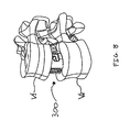
- FIG. 8 is a perspective view of a fusion implant disposed between two adjacent vertebrae in accordance with the present disclosure.
- proximal will refer to the end is closest to the operator, while the term “distal” will refer to the end that is farthest from the operator.
- distal will refer to the end that is farthest from the operator.
- cephalad is used in this application to indicate a direction toward a patient's head, whereas the term “caudad” indicates a direction toward the patient's feet.
- the term “medial” indicates a direction toward the middle of the body of the patient, whilst the term “lateral” indicates a direction toward a side of the body of the patient (i.e., away from the middle of the body of the patient).
- the term “posterior” indicates a direction toward the patient's back, and the term “anterior” indicates a direction toward the patient's front.
- FIG. 1 illustrates one portion of two identical portions of an intervertebral implant 10 (both portions shown in FIG. 5 ).
- the intervertebral implant 10 includes first and second members 20 , 30 .
- Each member 20 , 30 has a body 22 , 32 with a top surface 22 a , 32 a , a bottom surface 22 b , 32 b , an inside surface 22 c , 32 c , and an outside surface 22 d , 32 d .
- the top surface 22 a , 32 a and the bottom surface 22 b , 32 b include ridges 24 , 34 disposed thereon.
- the inside surface 22 c , 32 c has a first protuberance 26 , 36 distally disposed thereon and a second protuberance 28 , 38 proximally disposed thereon.
- Each protuberance 26 , 28 , 36 , 38 is configured and dimensioned to engage an intervertebral instrument 100 , 200 ( FIGS. 2 and 6 ).
- Each member 20 , 30 has a channel 25 , 35 cut therethrough. Each channel 25 , 35 extends from a respective first opening 25 a , 35 a disposed on each respective inside surface 22 c , 32 c , to a respective second opening 25 b , 35 b disposed on each respective outside surface 22 d , 32 d .
- a longitudinal passage 21 , 31 extends through each respective member 20 , 30 from a respective first aperture 21 a , 31 a disposed on the respective top surface 22 a , 32 a to a respective second aperture 21 b , 31 b disposed on the respective bottom surface 22 b , 32 b .
- Each channel 25 , 35 and each longitudinal passage 21 , 31 are configured and dimensioned to receive bone graft or bone enhancers to enable bone ingrowth.
- an intervertebral instrument 100 includes a shaft 110 having distal and proximal ends and an attaching feature 150 .
- the shaft 110 includes a sleeve 112 defining a first track 114 ( FIG. 2 ) and a second track 116 ( FIG. 5 ) extending longitudinally along a portion of opposing external surfaces of the shaft 110 .
- Each track 114 , 116 is configured and dimensioned to guide instruments used in intervertebral procedures, such as the first instrument 80 shown in FIG. 3 or the second instrument 90 shown in FIG. 4 (each of which is described below), as well as the respective members 20 , 30 of implants 10 toward the intervertebral disk space.
- the distal end of the sleeve 112 includes a pair of wings 118 , 120 orthogonally disposed relative to first and second track 114 , 116 .
- the wings 118 , 120 interconnect with each other by a contoured distal groove 119 .
- the pair of wings 118 , 120 are configured and dimensioned to distract an intervertebral disk space defined between two vertebrae.
- a handle 160 is removably attachable to the attaching feature 150 at the proximal end of the shaft 110 .
- the handle 160 includes a connector 162 centrally attached to an actuator 164 at the proximal end of the connector 162 .
- the actuator 164 includes grips 166 for engagement by a user's hand.
- the connector 164 is configured and dimensioned to distally and removably connect to the attaching feature 150 about the proximal end of the attaching feature 150 .
- the handle 160 is configured and dimensioned to enable the shaft 110 to be manipulated.
- the first instrument 80 includes a shaft 82 and a distracting tip 84 .
- the shaft 82 is configured and dimensioned to engage the sleeve 112 , 212 of each of the intervertebral instruments 100 , 200 ( FIGS. 2 and 6 ) so that the distracting tip 84 can be positioned within the intervertebral disk space in order to further facilitate the distraction of adjacent vertebrae “V 1 ” and “V 2 ” ( FIG. 8 ).
- the distracting tip further includes pointed heads 86 disposed at the distal end thereof, at least one cavity 88 disposed in the body thereof for receiving members 20 , 30 , and a measuring guide 89 disposed on the external surface of the body thereof for measuring the placement of members 20 , 30 .
- the second instrument 90 includes a shaft 92 and a distracting tip 94 .
- the shaft 92 is configured and dimensioned to engage the sleeve 112 , 212 of each of the intervertebral instruments 100 , 200 ( FIGS. 2 and 6 ) so that the distracting tip 94 can be positioned within the intervertebral disk space in order to further facilitate the distraction of adjacent vertebrae “V 1 ” and “V 2 ” ( FIG. 8 ).
- the distracting tip further includes a top platform 96 and a bottom platform 98 , each platform 96 , 98 including ridges 97 for engaging vertebrae “V 1 ” and “V 2 .” Each platform 96 , 98 is separated by a space 99 for receiving members 20 , 30 .
- the intervertebral instrument 200 is substantially similar to the intervertebral instrument 100 .
- the intervertebral instrument 200 includes a shaft 210 with tracks 214 , 216 and a removably attachable tip 270 at the distal end thereof.
- the removably attachable tip 270 removably attaches to the distal end of the sleeve 212 of the intervertebral instrument 200 by a pair of stems 213 a , 213 b .
- the removably attachable tip 270 is configured and dimensioned to engage the members 20 , 30 of the implant 10 .
- a pair of tracks 272 , 274 is partially longitudinally defined along opposing external surfaces of the removably attachable tip 270 .
- the tracks 272 , 274 are configured and dimensioned to guide the implants 10 ( FIG. 7 ) and their respective members 20 , 30 thereon.
- the removably attachable tip 270 is configured and dimensioned to keep the implants 10 affixed thereto.
- the removably attachable tip 270 is configured and dimensioned to engage each protuberance 26 , 28 , 36 , 38 of each respective member 20 , 30 ( FIG. 1 ). As illustrated in FIG.
- the intervertebral implant 10 and the removably attachable tip 270 are configured and dimensioned to collectively function as a unitary fusion implant 300 when the removably attachable tip 270 and each member 20 , 30 are collectively detached from the intervertebral instrument 200 .
- the fusion implant 300 is configured and dimensioned to remain implanted in the intervertebral disc space, i.e., between adjacent vertebrae V.
- the intervertebral instruments 100 , 200 , implants 10 , and implantable intervertebral disks 300 may be used during procedures performed anteriorly, posteriorly, laterally, and transforaminally.
- minimal disc space preparation is performed and the intervertebral instrument 100 , 200 is inserted into the disc space, preferably on its midline.
- the intervertebral instrument 100 , 200 is rotated approximately 90 degrees engaging the endplates and separating them by the height of the instrument.
- Several sized intervertebral instruments 100 , 200 are contemplated to allow for the variations between patients.
- Additional, complimentary instruments 80 , 90 may be passed down the tracks 114 , 116 , 214 , 216 to prepare the disc space for the implant 10 , or the implantable intervertebral disk 300 .
- Additional complimentary instruments include, but are not limited to, box chisels, scrapers and trial implants.
- the final intervertebral implants may be packed with bone graft and passed down the tracks 114 , 116 , 214 , 216 of the corresponding intervertebral instrument 100 , 200 .
- the intervertebral instrument 100 , 200 may be removed and the subsequent void may be filled with additional bone graft, potentially more than with a typical anterior approach implant.
- the removably attachable tip 270 is made of an implant grade material, preferably PEEK.
- the members 20 , 30 are passed down the intervertebral instrument 200 so that they may engage and lock to the removably attachable tip 270 .
- the implantable intervertebral disk 300 becomes a one-piece design and the removably attachable tip 270 and the members 20 , 30 collectively remain in the disc space as a unitary implant 300 . This design provides increased strength.
- Each of these intervertebral instruments 100 , 200 are configured and dimensioned to be used with a plurality of different sized patients.
- members 20 , 30 may be uniform unit without the removably attachable tip 270 , i.e. a single piece intervertebral implant.
Landscapes
- Health & Medical Sciences (AREA)
- Engineering & Computer Science (AREA)
- Biomedical Technology (AREA)
- Orthopedic Medicine & Surgery (AREA)
- Neurology (AREA)
- Transplantation (AREA)
- Heart & Thoracic Surgery (AREA)
- Oral & Maxillofacial Surgery (AREA)
- Cardiology (AREA)
- Vascular Medicine (AREA)
- Life Sciences & Earth Sciences (AREA)
- Animal Behavior & Ethology (AREA)
- General Health & Medical Sciences (AREA)
- Public Health (AREA)
- Veterinary Medicine (AREA)
- Physical Education & Sports Medicine (AREA)
- Prostheses (AREA)
Abstract
Description
Claims (7)
Priority Applications (1)
| Application Number | Priority Date | Filing Date | Title |
|---|---|---|---|
| US13/868,443 US8882844B2 (en) | 2008-03-07 | 2013-04-23 | Intervertebral instrument, implant, and method |
Applications Claiming Priority (3)
| Application Number | Priority Date | Filing Date | Title |
|---|---|---|---|
| US6856408P | 2008-03-07 | 2008-03-07 | |
| US12/398,316 US8449554B2 (en) | 2008-03-07 | 2009-03-05 | Intervertebral implant and instrument with removable section |
| US13/868,443 US8882844B2 (en) | 2008-03-07 | 2013-04-23 | Intervertebral instrument, implant, and method |
Related Parent Applications (1)
| Application Number | Title | Priority Date | Filing Date |
|---|---|---|---|
| US12/398,316 Division US8449554B2 (en) | 2008-03-07 | 2009-03-05 | Intervertebral implant and instrument with removable section |
Publications (2)
| Publication Number | Publication Date |
|---|---|
| US20130238097A1 US20130238097A1 (en) | 2013-09-12 |
| US8882844B2 true US8882844B2 (en) | 2014-11-11 |
Family
ID=41054473
Family Applications (2)
| Application Number | Title | Priority Date | Filing Date |
|---|---|---|---|
| US12/398,316 Active 2030-09-16 US8449554B2 (en) | 2008-03-07 | 2009-03-05 | Intervertebral implant and instrument with removable section |
| US13/868,443 Active US8882844B2 (en) | 2008-03-07 | 2013-04-23 | Intervertebral instrument, implant, and method |
Family Applications Before (1)
| Application Number | Title | Priority Date | Filing Date |
|---|---|---|---|
| US12/398,316 Active 2030-09-16 US8449554B2 (en) | 2008-03-07 | 2009-03-05 | Intervertebral implant and instrument with removable section |
Country Status (1)
| Country | Link |
|---|---|
| US (2) | US8449554B2 (en) |
Cited By (2)
| Publication number | Priority date | Publication date | Assignee | Title |
|---|---|---|---|---|
| US9730802B1 (en) | 2014-01-14 | 2017-08-15 | Nuvasive, Inc. | Spinal fusion implant and related methods |
| US10952866B2 (en) | 2015-10-13 | 2021-03-23 | DePuy Synthes Products, Inc. | Intervertebral implant and bone graft inserter |
Families Citing this family (40)
| Publication number | Priority date | Publication date | Assignee | Title |
|---|---|---|---|---|
| US8597360B2 (en) | 2004-11-03 | 2013-12-03 | Neuropro Technologies, Inc. | Bone fusion device |
| WO2006058221A2 (en) | 2004-11-24 | 2006-06-01 | Abdou Samy M | Devices and methods for inter-vertebral orthopedic device placement |
| US7824427B2 (en) * | 2007-01-16 | 2010-11-02 | Perez-Cruet Miquelangelo J | Minimally invasive interbody device |
| US8216317B2 (en) | 2008-03-31 | 2012-07-10 | Stryker Spine | Spinal implant apparatus and methods |
| US8147554B2 (en) * | 2008-10-13 | 2012-04-03 | Globus Medical, Inc. | Intervertebral spacer |
| US8764806B2 (en) | 2009-12-07 | 2014-07-01 | Samy Abdou | Devices and methods for minimally invasive spinal stabilization and instrumentation |
| US8945227B2 (en) * | 2010-02-01 | 2015-02-03 | X-Spine Systems, Inc. | Spinal implant co-insertion system and method |
| US8632595B2 (en) * | 2010-09-03 | 2014-01-21 | Globus Medical, Inc. | Expandable fusion device and method of installation thereof |
| US8425529B2 (en) | 2010-09-30 | 2013-04-23 | Stryker Spine | Instrument for inserting surgical implant with guiding rail |
| US8858637B2 (en) * | 2010-09-30 | 2014-10-14 | Stryker Spine | Surgical implant with guiding rail |
| US8603175B2 (en) | 2010-09-30 | 2013-12-10 | Stryker Spine | Method of inserting surgical implant with guiding rail |
| AU2011312111B2 (en) | 2010-10-08 | 2015-04-23 | K2M, Inc. | Lateral access system and method of use |
| US9358123B2 (en) | 2011-08-09 | 2016-06-07 | Neuropro Spinal Jaxx, Inc. | Bone fusion device, apparatus and method |
| US10420654B2 (en) | 2011-08-09 | 2019-09-24 | Neuropro Technologies, Inc. | Bone fusion device, system and method |
| WO2013023096A1 (en) | 2011-08-09 | 2013-02-14 | Neuropro Technologies, Inc. | Bone fusion device, system and method |
| US8845728B1 (en) | 2011-09-23 | 2014-09-30 | Samy Abdou | Spinal fixation devices and methods of use |
| US20130226240A1 (en) | 2012-02-22 | 2013-08-29 | Samy Abdou | Spinous process fixation devices and methods of use |
| US20130261747A1 (en) * | 2012-03-30 | 2013-10-03 | Christophe Geisert | ALIF Spinal Implant |
| US10159583B2 (en) * | 2012-04-13 | 2018-12-25 | Neuropro Technologies, Inc. | Bone fusion device |
| US9532883B2 (en) | 2012-04-13 | 2017-01-03 | Neuropro Technologies, Inc. | Bone fusion device |
| US9198767B2 (en) | 2012-08-28 | 2015-12-01 | Samy Abdou | Devices and methods for spinal stabilization and instrumentation |
| US9320617B2 (en) | 2012-10-22 | 2016-04-26 | Cogent Spine, LLC | Devices and methods for spinal stabilization and instrumentation |
| US8864830B2 (en) * | 2013-03-12 | 2014-10-21 | Spine Wave, Inc. | Apparatus and methods for inserting an interbody fusion device |
| US10327910B2 (en) | 2013-03-14 | 2019-06-25 | X-Spine Systems, Inc. | Spinal implant and assembly |
| AU2014236698B2 (en) | 2013-03-15 | 2018-09-13 | Neuropro Technologies, Inc. | Bodiless bone fusion device, apparatus and method |
| AU2016213808B2 (en) | 2015-08-12 | 2020-09-10 | Vb Spine Us Opco Llc | Orthopedic surgical system including surgical access systems, distraction systems, and methods of using same |
| US10499894B2 (en) | 2015-08-12 | 2019-12-10 | K2M, Inc. | Orthopedic surgical system including surgical access systems, distraction systems, and methods of using same |
| US10857003B1 (en) | 2015-10-14 | 2020-12-08 | Samy Abdou | Devices and methods for vertebral stabilization |
| AU2017235887B2 (en) | 2016-09-26 | 2021-09-30 | K2M, Inc. | Retraction system and method of use |
| US10744000B1 (en) | 2016-10-25 | 2020-08-18 | Samy Abdou | Devices and methods for vertebral bone realignment |
| US10973648B1 (en) | 2016-10-25 | 2021-04-13 | Samy Abdou | Devices and methods for vertebral bone realignment |
| US10111760B2 (en) * | 2017-01-18 | 2018-10-30 | Neuropro Technologies, Inc. | Bone fusion system, device and method including a measuring mechanism |
| US10213321B2 (en) | 2017-01-18 | 2019-02-26 | Neuropro Technologies, Inc. | Bone fusion system, device and method including delivery apparatus |
| US10973657B2 (en) | 2017-01-18 | 2021-04-13 | Neuropro Technologies, Inc. | Bone fusion surgical system and method |
| US10729560B2 (en) | 2017-01-18 | 2020-08-04 | Neuropro Technologies, Inc. | Bone fusion system, device and method including an insertion instrument |
| US11179248B2 (en) | 2018-10-02 | 2021-11-23 | Samy Abdou | Devices and methods for spinal implantation |
| CN110693631B (en) * | 2019-10-17 | 2023-06-27 | 徐州市中心医院 | A reverse intervertebral intervertebral fusion device under endoscopy |
| US12318307B2 (en) | 2021-07-16 | 2025-06-03 | Blue Ocean Spine Gmbh | Adjustable spinal implants, associated instruments and methods |
| US12453640B2 (en) | 2021-07-16 | 2025-10-28 | Blue Ocean Spine Gmbh | Adjustable spinal implants, associated instruments and methods |
| WO2024153755A1 (en) | 2023-01-18 | 2024-07-25 | Blue Ocean Spine Gmbh | Adjustable spinal implants and related deployment instruments |
Citations (50)
| Publication number | Priority date | Publication date | Assignee | Title |
|---|---|---|---|---|
| US5431658A (en) | 1994-02-14 | 1995-07-11 | Moskovich; Ronald | Facilitator for vertebrae grafts and prostheses |
| US5599279A (en) | 1994-03-16 | 1997-02-04 | Gus J. Slotman | Surgical instruments and method useful for endoscopic spinal procedures |
| US6569168B2 (en) | 2000-05-05 | 2003-05-27 | Osteotech, Inc. | Intervertebral distractor and implant insertion instrument |
| US20030149438A1 (en) | 2001-04-30 | 2003-08-07 | Howmedica Osteonics Corp. | Insertion instrument |
| US20030195520A1 (en) * | 1999-02-04 | 2003-10-16 | Boyd Lawrence M. | Methods and instrumentation for vertebral interbody fusion |
| US20040002758A1 (en) | 2002-03-11 | 2004-01-01 | Landry Michael E. | Spinal implant including a compressible connector |
| US20040024408A1 (en) | 1999-02-04 | 2004-02-05 | Burkus J. Kenneth | Methods and instrumentation for vertebral interbody fusion |
| US6770074B2 (en) | 1988-06-13 | 2004-08-03 | Gary Karlin Michelson | Apparatus for use in inserting spinal implants |
| US20040172037A1 (en) | 1999-08-26 | 2004-09-02 | Dorchak John D. | Devices and methods for implanting fusion cages |
| US20040267277A1 (en) | 2003-06-30 | 2004-12-30 | Zannis Anthony D. | Implant delivery instrument |
| US20050021042A1 (en) | 2003-07-21 | 2005-01-27 | Theirry Marnay | Instruments and method for inserting an intervertebral implant |
| US20050113842A1 (en) | 2002-05-06 | 2005-05-26 | Rudolf Bertagnoli | Instrumentation and methods for preparation of an intervertebral space |
| US20050165408A1 (en) | 2004-01-26 | 2005-07-28 | Puno Rolando M. | Methods and instrumentation for inserting intervertebral grafts and devices |
| US20050182416A1 (en) | 2004-02-13 | 2005-08-18 | Roy Lim | Spacer with height and angle adjustments for spacing vertebral members |
| US6986772B2 (en) | 2001-03-01 | 2006-01-17 | Michelson Gary K | Dynamic lordotic guard with movable extensions for creating an implantation space posteriorly in the lumbar spine |
| US20060030862A1 (en) | 2003-01-31 | 2006-02-09 | Spinalmotion, Inc. | Intervertebral prosthesis placement instrument |
| US20060030857A1 (en) | 2004-08-06 | 2006-02-09 | Spinalmotion, Inc. | Methods and apparatus for intervertebral disc prosthesis insertion |
| US20060030856A1 (en) | 2004-07-21 | 2006-02-09 | Sdgi Holding, Inc. | Dual distractor inserter |
| US20060052793A1 (en) | 2004-08-20 | 2006-03-09 | Heinz Eric S | Instrumentation and methods for vertebral distraction |
| US20060064107A1 (en) | 2004-09-23 | 2006-03-23 | Rudi Bertagnoli | Distractor for lumbar insertion instrument |
| US20060095043A1 (en) | 2004-10-19 | 2006-05-04 | Martz Erik O | Adjustable instrumentation for spinal implant insertion |
| US7070598B2 (en) | 2002-06-25 | 2006-07-04 | Sdgi Holdings, Inc. | Minimally invasive expanding spacer and method |
| US20060149284A1 (en) | 2004-12-15 | 2006-07-06 | Sdgi Holdings, Inc. | Insertion device and method for inserting a member within the body |
| US20060161166A1 (en) * | 2001-03-08 | 2006-07-20 | Spine Wave, Inc. | Tissue distraction device |
| US20060167461A1 (en) | 2003-03-31 | 2006-07-27 | Hawkins John R | Method and apparatus for artificial disc insertion |
| US7087055B2 (en) | 2002-06-25 | 2006-08-08 | Sdgi Holdings, Inc. | Minimally invasive expanding spacer and method |
| US20060235423A1 (en) | 2005-04-01 | 2006-10-19 | Cantu Alberto R | Apparatus having at least one actuatable planar surface and method using the same for a spinal procedure |
| US20060241643A1 (en) | 2002-06-25 | 2006-10-26 | Roy Lim | Minimally invasive expanding spacer and method |
| US20060241641A1 (en) | 2005-04-22 | 2006-10-26 | Sdgi Holdings, Inc. | Methods and instrumentation for distraction and insertion of implants in a spinal disc space |
| US20070016221A1 (en) | 1999-09-14 | 2007-01-18 | Boris Beyersdorff | Insertion instrument for an intervertebral implant |
| US20070016220A1 (en) | 2001-03-01 | 2007-01-18 | Sdgi Holding, Inc. | Method for using dynamic lordotic guard |
| US20070123904A1 (en) | 2005-10-31 | 2007-05-31 | Depuy Spine, Inc. | Distraction instrument and method for distracting an intervertebral site |
| US20070123901A1 (en) | 2000-10-20 | 2007-05-31 | Foley Kevin T | Methods and instruments for interbody surgical techniques |
| US20070123903A1 (en) | 2005-10-31 | 2007-05-31 | Depuy Spine, Inc. | Medical Device installation tool and methods of use |
| US20070191857A1 (en) | 2006-01-31 | 2007-08-16 | Sdgi Holdings, Inc. | Spinal disc replacement surgical instrument and methods for use in spinal disc replacement |
| US20070198025A1 (en) | 2000-08-30 | 2007-08-23 | Trieu Hai H | Method and apparatus for delivering an intervertebral disc implant |
| US20070233143A1 (en) | 2006-03-14 | 2007-10-04 | Sdgi Holdings, Inc. | Spinal disc space preparation instruments and methods for interbody spinal implants |
| US20070260315A1 (en) | 2006-05-03 | 2007-11-08 | Foley Kevin T | Devices and methods for disc height restoration |
| US20070270873A1 (en) | 2006-04-20 | 2007-11-22 | Eric Flickinger | Monorail system |
| US20080077153A1 (en) | 2006-09-22 | 2008-03-27 | Pioneer Surgical Technology, Inc. | System and methods for inserting a spinal disc device into an intervertebral space |
| US20080114367A1 (en) | 2006-11-10 | 2008-05-15 | Syberspine Limited | Method and relaxable distracters for in-situ formation of intervertebral disc prosthesis |
| US20080161817A1 (en) | 2006-09-28 | 2008-07-03 | Depuy Spine, Inc. | Intervertebral distraction device |
| US20080177275A1 (en) | 2006-12-01 | 2008-07-24 | Charles Wing | Interbody distractor |
| US7445637B2 (en) | 2001-08-08 | 2008-11-04 | Jean Taylor | Vertebra stabilizing assembly |
| US7473256B2 (en) | 2003-10-23 | 2009-01-06 | Trans1 Inc. | Method and apparatus for spinal distraction |
| US7476252B2 (en) | 2002-10-21 | 2009-01-13 | Warsaw Orthopedic, Inc. | System and techniques for restoring and maintaining intervertebral anatomy |
| US7481812B2 (en) | 1999-10-21 | 2009-01-27 | Warsaw Orthopedic, Inc. | Devices and techniques for a posterior lateral disc space approach |
| US7485120B2 (en) | 2003-12-31 | 2009-02-03 | Ray Charles D | Tapered bone fusion cages or blocks, implantation means and method |
| US20090306671A1 (en) * | 2008-06-06 | 2009-12-10 | Providence Medical Technology, Inc. | Facet joint implants and delivery tools |
| US8016829B2 (en) * | 2004-02-09 | 2011-09-13 | Depuy Spine, Inc. | Systems and methods for spinal surgery |
Family Cites Families (1)
| Publication number | Priority date | Publication date | Assignee | Title |
|---|---|---|---|---|
| US1476252A (en) | 1921-12-15 | 1923-12-04 | Albert C Hempel | Sparking device for internal-combustion motors |
-
2009
- 2009-03-05 US US12/398,316 patent/US8449554B2/en active Active
-
2013
- 2013-04-23 US US13/868,443 patent/US8882844B2/en active Active
Patent Citations (50)
| Publication number | Priority date | Publication date | Assignee | Title |
|---|---|---|---|---|
| US6770074B2 (en) | 1988-06-13 | 2004-08-03 | Gary Karlin Michelson | Apparatus for use in inserting spinal implants |
| US5431658A (en) | 1994-02-14 | 1995-07-11 | Moskovich; Ronald | Facilitator for vertebrae grafts and prostheses |
| US5599279A (en) | 1994-03-16 | 1997-02-04 | Gus J. Slotman | Surgical instruments and method useful for endoscopic spinal procedures |
| US20030195520A1 (en) * | 1999-02-04 | 2003-10-16 | Boyd Lawrence M. | Methods and instrumentation for vertebral interbody fusion |
| US20040024408A1 (en) | 1999-02-04 | 2004-02-05 | Burkus J. Kenneth | Methods and instrumentation for vertebral interbody fusion |
| US20040172037A1 (en) | 1999-08-26 | 2004-09-02 | Dorchak John D. | Devices and methods for implanting fusion cages |
| US20070016221A1 (en) | 1999-09-14 | 2007-01-18 | Boris Beyersdorff | Insertion instrument for an intervertebral implant |
| US7481812B2 (en) | 1999-10-21 | 2009-01-27 | Warsaw Orthopedic, Inc. | Devices and techniques for a posterior lateral disc space approach |
| US6569168B2 (en) | 2000-05-05 | 2003-05-27 | Osteotech, Inc. | Intervertebral distractor and implant insertion instrument |
| US20070198025A1 (en) | 2000-08-30 | 2007-08-23 | Trieu Hai H | Method and apparatus for delivering an intervertebral disc implant |
| US20070123901A1 (en) | 2000-10-20 | 2007-05-31 | Foley Kevin T | Methods and instruments for interbody surgical techniques |
| US6986772B2 (en) | 2001-03-01 | 2006-01-17 | Michelson Gary K | Dynamic lordotic guard with movable extensions for creating an implantation space posteriorly in the lumbar spine |
| US20070016220A1 (en) | 2001-03-01 | 2007-01-18 | Sdgi Holding, Inc. | Method for using dynamic lordotic guard |
| US20060161166A1 (en) * | 2001-03-08 | 2006-07-20 | Spine Wave, Inc. | Tissue distraction device |
| US20030149438A1 (en) | 2001-04-30 | 2003-08-07 | Howmedica Osteonics Corp. | Insertion instrument |
| US7445637B2 (en) | 2001-08-08 | 2008-11-04 | Jean Taylor | Vertebra stabilizing assembly |
| US20040002758A1 (en) | 2002-03-11 | 2004-01-01 | Landry Michael E. | Spinal implant including a compressible connector |
| US20050113842A1 (en) | 2002-05-06 | 2005-05-26 | Rudolf Bertagnoli | Instrumentation and methods for preparation of an intervertebral space |
| US20060241643A1 (en) | 2002-06-25 | 2006-10-26 | Roy Lim | Minimally invasive expanding spacer and method |
| US7087055B2 (en) | 2002-06-25 | 2006-08-08 | Sdgi Holdings, Inc. | Minimally invasive expanding spacer and method |
| US7070598B2 (en) | 2002-06-25 | 2006-07-04 | Sdgi Holdings, Inc. | Minimally invasive expanding spacer and method |
| US7476252B2 (en) | 2002-10-21 | 2009-01-13 | Warsaw Orthopedic, Inc. | System and techniques for restoring and maintaining intervertebral anatomy |
| US20060030862A1 (en) | 2003-01-31 | 2006-02-09 | Spinalmotion, Inc. | Intervertebral prosthesis placement instrument |
| US20060167461A1 (en) | 2003-03-31 | 2006-07-27 | Hawkins John R | Method and apparatus for artificial disc insertion |
| US20040267277A1 (en) | 2003-06-30 | 2004-12-30 | Zannis Anthony D. | Implant delivery instrument |
| US20050021042A1 (en) | 2003-07-21 | 2005-01-27 | Theirry Marnay | Instruments and method for inserting an intervertebral implant |
| US7473256B2 (en) | 2003-10-23 | 2009-01-06 | Trans1 Inc. | Method and apparatus for spinal distraction |
| US7485120B2 (en) | 2003-12-31 | 2009-02-03 | Ray Charles D | Tapered bone fusion cages or blocks, implantation means and method |
| US20050165408A1 (en) | 2004-01-26 | 2005-07-28 | Puno Rolando M. | Methods and instrumentation for inserting intervertebral grafts and devices |
| US8016829B2 (en) * | 2004-02-09 | 2011-09-13 | Depuy Spine, Inc. | Systems and methods for spinal surgery |
| US20050182416A1 (en) | 2004-02-13 | 2005-08-18 | Roy Lim | Spacer with height and angle adjustments for spacing vertebral members |
| US20060030856A1 (en) | 2004-07-21 | 2006-02-09 | Sdgi Holding, Inc. | Dual distractor inserter |
| US20060030857A1 (en) | 2004-08-06 | 2006-02-09 | Spinalmotion, Inc. | Methods and apparatus for intervertebral disc prosthesis insertion |
| US20060052793A1 (en) | 2004-08-20 | 2006-03-09 | Heinz Eric S | Instrumentation and methods for vertebral distraction |
| US20060064107A1 (en) | 2004-09-23 | 2006-03-23 | Rudi Bertagnoli | Distractor for lumbar insertion instrument |
| US20060095043A1 (en) | 2004-10-19 | 2006-05-04 | Martz Erik O | Adjustable instrumentation for spinal implant insertion |
| US20060149284A1 (en) | 2004-12-15 | 2006-07-06 | Sdgi Holdings, Inc. | Insertion device and method for inserting a member within the body |
| US20060235423A1 (en) | 2005-04-01 | 2006-10-19 | Cantu Alberto R | Apparatus having at least one actuatable planar surface and method using the same for a spinal procedure |
| US20060241641A1 (en) | 2005-04-22 | 2006-10-26 | Sdgi Holdings, Inc. | Methods and instrumentation for distraction and insertion of implants in a spinal disc space |
| US20070123904A1 (en) | 2005-10-31 | 2007-05-31 | Depuy Spine, Inc. | Distraction instrument and method for distracting an intervertebral site |
| US20070123903A1 (en) | 2005-10-31 | 2007-05-31 | Depuy Spine, Inc. | Medical Device installation tool and methods of use |
| US20070191857A1 (en) | 2006-01-31 | 2007-08-16 | Sdgi Holdings, Inc. | Spinal disc replacement surgical instrument and methods for use in spinal disc replacement |
| US20070233143A1 (en) | 2006-03-14 | 2007-10-04 | Sdgi Holdings, Inc. | Spinal disc space preparation instruments and methods for interbody spinal implants |
| US20070270873A1 (en) | 2006-04-20 | 2007-11-22 | Eric Flickinger | Monorail system |
| US20070260315A1 (en) | 2006-05-03 | 2007-11-08 | Foley Kevin T | Devices and methods for disc height restoration |
| US20080077153A1 (en) | 2006-09-22 | 2008-03-27 | Pioneer Surgical Technology, Inc. | System and methods for inserting a spinal disc device into an intervertebral space |
| US20080161817A1 (en) | 2006-09-28 | 2008-07-03 | Depuy Spine, Inc. | Intervertebral distraction device |
| US20080114367A1 (en) | 2006-11-10 | 2008-05-15 | Syberspine Limited | Method and relaxable distracters for in-situ formation of intervertebral disc prosthesis |
| US20080177275A1 (en) | 2006-12-01 | 2008-07-24 | Charles Wing | Interbody distractor |
| US20090306671A1 (en) * | 2008-06-06 | 2009-12-10 | Providence Medical Technology, Inc. | Facet joint implants and delivery tools |
Cited By (5)
| Publication number | Priority date | Publication date | Assignee | Title |
|---|---|---|---|---|
| US9730802B1 (en) | 2014-01-14 | 2017-08-15 | Nuvasive, Inc. | Spinal fusion implant and related methods |
| US10335287B2 (en) | 2014-01-14 | 2019-07-02 | Nuvasive, Inc. | Spinal fusion implant and related methods |
| US11497621B2 (en) | 2014-01-14 | 2022-11-15 | Nuvasive, Inc. | Inserter for implanting a spinal implant |
| US12127948B2 (en) | 2014-01-14 | 2024-10-29 | Globus Medical Inc. | System for implanting a spinal fusion implant and related methods |
| US10952866B2 (en) | 2015-10-13 | 2021-03-23 | DePuy Synthes Products, Inc. | Intervertebral implant and bone graft inserter |
Also Published As
| Publication number | Publication date |
|---|---|
| US20090228110A1 (en) | 2009-09-10 |
| US20130238097A1 (en) | 2013-09-12 |
| US8449554B2 (en) | 2013-05-28 |
Similar Documents
| Publication | Publication Date | Title |
|---|---|---|
| US8882844B2 (en) | Intervertebral instrument, implant, and method | |
| US12239551B2 (en) | Sagittal balance systems and methods of use thereof | |
| US11712341B2 (en) | Expandable intervertebral implant | |
| USRE38614E1 (en) | Intervertebral allograft spacer | |
| US6258125B1 (en) | Intervertebral allograft spacer | |
| US9101492B2 (en) | Set comprising an intervertebral implant for immobilising a vertebra with respect to another and an instrument for installing this implant | |
| US7060097B2 (en) | Method and apparatus for implant stability | |
| US11517452B2 (en) | Surgical instrument and methods of use thereof | |
| US8460387B2 (en) | Intervertebral implant and face plate combination | |
| US8632550B2 (en) | System and method for providing surgical access to a spine | |
| US8382767B2 (en) | Implant insertion tool | |
| US9707099B2 (en) | Anterior lumbar fusion method and device | |
| US20080306598A1 (en) | Spinal implant with biologic sponge | |
| US20060287728A1 (en) | System and method for implanting intervertebral disk prostheses | |
| KR20110050462A (en) | Modular Hydronuclear Prosthetics | |
| US8343164B2 (en) | Implant insertion tool | |
| KR102097624B1 (en) | Space expanding intervertebral fusion cage device | |
| US20080262501A1 (en) | Multi-function corpectomy instrument | |
| CN113520677A (en) | Minimally invasive endoscopic implantation expandable lumbar interbody fusion cage | |
| CN105662659B (en) | A kind of lumbosacral spine is axial to merge inner fixing device and its application method | |
| CN213963781U (en) | Multifunctional lumbar vertebra hinge fusion cage | |
| KR102379915B1 (en) | Cage for minimal invasive surgery | |
| CN112315629A (en) | A multifunctional lumbar hinge fusion cage | |
| CN112716663A (en) | Split type parallel fusion cage for lumbar vertebrae | |
| HK1036747B (en) | Intervertebral allograft spacer |
Legal Events
| Date | Code | Title | Description |
|---|---|---|---|
| AS | Assignment |
Owner name: K2M, INC., VIRGINIA Free format text: ASSIGNMENT OF ASSIGNORS INTEREST;ASSIGNOR:MCCLINTOCK, LARRY;REEL/FRAME:032168/0487 Effective date: 20090305 |
|
| AS | Assignment |
Owner name: SILICON VALLEY BANK, CALIFORNIA Free format text: FIRST AMENDMENT TO PATENT SECURITY AGREEMENT;ASSIGNORS:K2M, INC.;K2M UNLIMITED;K2M HOLDINGS, INC.;REEL/FRAME:034034/0097 Effective date: 20141021 |
|
| STCF | Information on status: patent grant |
Free format text: PATENTED CASE |
|
| AS | Assignment |
Owner name: SILICON VALLEY BANK, AS ADMINISTRATIVE AGENT, CALIFORNIA Free format text: SECOND AMENDMENT TO PATENT SECURITY AGREEMENT;ASSIGNORS:K2M, INC.;K2M HOLDINGS, INC.;K2M UK LIMITED;REEL/FRAME:037091/0221 Effective date: 20151029 Owner name: SILICON VALLEY BANK, AS ADMINISTRATIVE AGENT, CALI Free format text: SECOND AMENDMENT TO PATENT SECURITY AGREEMENT;ASSIGNORS:K2M, INC.;K2M HOLDINGS, INC.;K2M UK LIMITED;REEL/FRAME:037091/0221 Effective date: 20151029 |
|
| FEPP | Fee payment procedure |
Free format text: ENTITY STATUS SET TO UNDISCOUNTED (ORIGINAL EVENT CODE: BIG.) |
|
| MAFP | Maintenance fee payment |
Free format text: PAYMENT OF MAINTENANCE FEE, 4TH YEAR, LARGE ENTITY (ORIGINAL EVENT CODE: M1551) Year of fee payment: 4 |
|
| AS | Assignment |
Owner name: K2M, INC., VIRGINIA Free format text: RELEASE BY SECURED PARTY;ASSIGNOR:SILICON VALLEY BANK;REEL/FRAME:047496/0001 Effective date: 20181109 Owner name: K2M HOLDINGS, INC., VIRGINIA Free format text: RELEASE BY SECURED PARTY;ASSIGNOR:SILICON VALLEY BANK;REEL/FRAME:047496/0001 Effective date: 20181109 Owner name: K2M UK LIMITED, UNITED KINGDOM Free format text: RELEASE BY SECURED PARTY;ASSIGNOR:SILICON VALLEY BANK;REEL/FRAME:047496/0001 Effective date: 20181109 |
|
| MAFP | Maintenance fee payment |
Free format text: PAYMENT OF MAINTENANCE FEE, 8TH YEAR, LARGE ENTITY (ORIGINAL EVENT CODE: M1552); ENTITY STATUS OF PATENT OWNER: LARGE ENTITY Year of fee payment: 8 |
|
| AS | Assignment |
Owner name: STRYKER CORPORATION, MICHIGAN Free format text: ASSIGNMENT OF ASSIGNORS INTEREST;ASSIGNOR:K2M, INC.;REEL/FRAME:071271/0170 Effective date: 20250328 |
|
| AS | Assignment |
Owner name: VB SPINE US OPCO LLC, DELAWARE Free format text: ASSIGNMENT OF ASSIGNORS INTEREST;ASSIGNOR:STRYKER CORPORATION;REEL/FRAME:071312/0356 Effective date: 20250505 |
|
| AS | Assignment |
Owner name: ANKURA TRUST COMPANY, LLC, AS COLLATERAL AGENT, CONNECTICUT Free format text: PATENT SECURITY AGREEMENT;ASSIGNORS:K2M, INC.;VB SPINE US OPCO LLC;VB SPINE LLC;REEL/FRAME:071682/0116 Effective date: 20250616 |