US8881892B1 - Container - Google Patents
Container Download PDFInfo
- Publication number
- US8881892B1 US8881892B1 US14/035,696 US201314035696A US8881892B1 US 8881892 B1 US8881892 B1 US 8881892B1 US 201314035696 A US201314035696 A US 201314035696A US 8881892 B1 US8881892 B1 US 8881892B1
- Authority
- US
- United States
- Prior art keywords
- eye
- chamber
- membrane
- mountable device
- container
- Prior art date
- Legal status (The legal status is an assumption and is not a legal conclusion. Google has not performed a legal analysis and makes no representation as to the accuracy of the status listed.)
- Expired - Fee Related
Links
Images


Classifications
-
- A—HUMAN NECESSITIES
- A45—HAND OR TRAVELLING ARTICLES
- A45C—PURSES; LUGGAGE; HAND CARRIED BAGS
- A45C11/00—Receptacles for purposes not provided for in groups A45C1/00-A45C9/00
- A45C11/005—Contact lens cases
-
- A—HUMAN NECESSITIES
- A61—MEDICAL OR VETERINARY SCIENCE; HYGIENE
- A61B—DIAGNOSIS; SURGERY; IDENTIFICATION
- A61B5/00—Measuring for diagnostic purposes; Identification of persons
- A61B5/145—Measuring characteristics of blood in vivo, e.g. gas concentration or pH-value ; Measuring characteristics of body fluids or tissues, e.g. interstitial fluid or cerebral tissue
- A61B5/14507—Measuring characteristics of blood in vivo, e.g. gas concentration or pH-value ; Measuring characteristics of body fluids or tissues, e.g. interstitial fluid or cerebral tissue specially adapted for measuring characteristics of body fluids other than blood
-
- B—PERFORMING OPERATIONS; TRANSPORTING
- B65—CONVEYING; PACKING; STORING; HANDLING THIN OR FILAMENTARY MATERIAL
- B65D—CONTAINERS FOR STORAGE OR TRANSPORT OF ARTICLES OR MATERIALS, e.g. BAGS, BARRELS, BOTTLES, BOXES, CANS, CARTONS, CRATES, DRUMS, JARS, TANKS, HOPPERS, FORWARDING CONTAINERS; ACCESSORIES, CLOSURES, OR FITTINGS THEREFOR; PACKAGING ELEMENTS; PACKAGES
- B65D25/00—Details of other kinds or types of rigid or semi-rigid containers
- B65D25/02—Internal fittings
- B65D25/04—Partitions
- B65D25/08—Partitions with provisions for removing or destroying, e.g. to facilitate mixing of contents
-
- B—PERFORMING OPERATIONS; TRANSPORTING
- B65—CONVEYING; PACKING; STORING; HANDLING THIN OR FILAMENTARY MATERIAL
- B65D—CONTAINERS FOR STORAGE OR TRANSPORT OF ARTICLES OR MATERIALS, e.g. BAGS, BARRELS, BOTTLES, BOXES, CANS, CARTONS, CRATES, DRUMS, JARS, TANKS, HOPPERS, FORWARDING CONTAINERS; ACCESSORIES, CLOSURES, OR FITTINGS THEREFOR; PACKAGING ELEMENTS; PACKAGES
- B65D77/00—Packages formed by enclosing articles or materials in preformed containers, e.g. boxes, cartons, sacks or bags
- B65D77/08—Materials, e.g. different materials, enclosed in separate compartments formed during filling of a single container
-
- A—HUMAN NECESSITIES
- A61—MEDICAL OR VETERINARY SCIENCE; HYGIENE
- A61B—DIAGNOSIS; SURGERY; IDENTIFICATION
- A61B3/00—Apparatus for testing the eyes; Instruments for examining the eyes
- A61B3/10—Objective types, i.e. instruments for examining the eyes independent of the patients' perceptions or reactions
- A61B3/101—Objective types, i.e. instruments for examining the eyes independent of the patients' perceptions or reactions for examining the tear film
-
- A—HUMAN NECESSITIES
- A61—MEDICAL OR VETERINARY SCIENCE; HYGIENE
- A61B—DIAGNOSIS; SURGERY; IDENTIFICATION
- A61B5/00—Measuring for diagnostic purposes; Identification of persons
- A61B5/145—Measuring characteristics of blood in vivo, e.g. gas concentration or pH-value ; Measuring characteristics of body fluids or tissues, e.g. interstitial fluid or cerebral tissue
- A61B5/14532—Measuring characteristics of blood in vivo, e.g. gas concentration or pH-value ; Measuring characteristics of body fluids or tissues, e.g. interstitial fluid or cerebral tissue for measuring glucose, e.g. by tissue impedance measurement
-
- A—HUMAN NECESSITIES
- A61—MEDICAL OR VETERINARY SCIENCE; HYGIENE
- A61B—DIAGNOSIS; SURGERY; IDENTIFICATION
- A61B5/00—Measuring for diagnostic purposes; Identification of persons
- A61B5/145—Measuring characteristics of blood in vivo, e.g. gas concentration or pH-value ; Measuring characteristics of body fluids or tissues, e.g. interstitial fluid or cerebral tissue
- A61B5/14542—Measuring characteristics of blood in vivo, e.g. gas concentration or pH-value ; Measuring characteristics of body fluids or tissues, e.g. interstitial fluid or cerebral tissue for measuring blood gases
-
- A—HUMAN NECESSITIES
- A61—MEDICAL OR VETERINARY SCIENCE; HYGIENE
- A61B—DIAGNOSIS; SURGERY; IDENTIFICATION
- A61B5/00—Measuring for diagnostic purposes; Identification of persons
- A61B5/145—Measuring characteristics of blood in vivo, e.g. gas concentration or pH-value ; Measuring characteristics of body fluids or tissues, e.g. interstitial fluid or cerebral tissue
- A61B5/1468—Measuring characteristics of blood in vivo, e.g. gas concentration or pH-value ; Measuring characteristics of body fluids or tissues, e.g. interstitial fluid or cerebral tissue using chemical or electrochemical methods, e.g. by polarographic means
- A61B5/1486—Measuring characteristics of blood in vivo, e.g. gas concentration or pH-value ; Measuring characteristics of body fluids or tissues, e.g. interstitial fluid or cerebral tissue using chemical or electrochemical methods, e.g. by polarographic means using enzyme electrodes, e.g. with immobilised oxidase
-
- A—HUMAN NECESSITIES
- A61—MEDICAL OR VETERINARY SCIENCE; HYGIENE
- A61B—DIAGNOSIS; SURGERY; IDENTIFICATION
- A61B5/00—Measuring for diagnostic purposes; Identification of persons
- A61B5/68—Arrangements of detecting, measuring or recording means, e.g. sensors, in relation to patient
- A61B5/6801—Arrangements of detecting, measuring or recording means, e.g. sensors, in relation to patient specially adapted to be attached to or worn on the body surface
- A61B5/6802—Sensor mounted on worn items
- A61B5/6803—Head-worn items, e.g. helmets, masks, headphones or goggles
-
- A—HUMAN NECESSITIES
- A61—MEDICAL OR VETERINARY SCIENCE; HYGIENE
- A61B—DIAGNOSIS; SURGERY; IDENTIFICATION
- A61B5/00—Measuring for diagnostic purposes; Identification of persons
- A61B5/68—Arrangements of detecting, measuring or recording means, e.g. sensors, in relation to patient
- A61B5/6801—Arrangements of detecting, measuring or recording means, e.g. sensors, in relation to patient specially adapted to be attached to or worn on the body surface
- A61B5/6813—Specially adapted to be attached to a specific body part
- A61B5/6814—Head
- A61B5/6821—Eye
-
- B—PERFORMING OPERATIONS; TRANSPORTING
- B65—CONVEYING; PACKING; STORING; HANDLING THIN OR FILAMENTARY MATERIAL
- B65D—CONTAINERS FOR STORAGE OR TRANSPORT OF ARTICLES OR MATERIALS, e.g. BAGS, BARRELS, BOTTLES, BOXES, CANS, CARTONS, CRATES, DRUMS, JARS, TANKS, HOPPERS, FORWARDING CONTAINERS; ACCESSORIES, CLOSURES, OR FITTINGS THEREFOR; PACKAGING ELEMENTS; PACKAGES
- B65D2585/00—Containers, packaging elements or packages specially adapted for particular articles or materials
- B65D2585/54—Containers, packaging elements or packages specially adapted for particular articles or materials for articles of special shape not otherwise provided for
- B65D2585/545—Contact lenses
Definitions
- a body-mountable device may be configured to monitor health-related information based on at least one analyte detected in a fluid of a user wearing the body-mountable device.
- the body-mountable device may comprise an eye-mountable device that may be in the form of a contact lens that includes a sensor configured to detect the at least one analyte (e.g., glucose in a tear film of a user wearing the eye-mountable device).
- the body-mountable device may also be configured to monitor various other types of health-related information.
- the present disclosure provides an apparatus including a first chamber containing an eye-mountable device.
- the apparatus may also include a second chamber containing an aqueous solution.
- the apparatus may also include a membrane positioned between the first chamber and the second chamber. The membrane may be configured to rupture based on application of a force to the apparatus. The ruptured membrane may allow the aqueous solution to engage with the eye-mountable device.
- the apparatus may also include a lid to seal one or more of the first chamber and the second chamber.
- the present disclosure provides an apparatus including a container having external surfaces and an opening.
- the apparatus may also include a membrane separating the container into a first chamber and a second chamber.
- the first chamber may contain an eye mountable device, and the second chamber may contain an aqueous solution.
- the membrane may be configured to rupture based on application of a force to the apparatus. The ruptured membrane may allow the aqueous solution to engage with the eye-mountable device.
- the apparatus may also include a lid configured to seal the opening of the container.
- the present disclosure provides a method including providing a container having an opening.
- the method may also include providing an eye-mountable device in a first chamber of the container.
- the method may also include providing an aqueous solution in a second chamber of the container.
- the method may also include providing a membrane to divide the container into the first chamber and the second chamber. The membrane may be configured to rupture based on application of a force to the container to enable the aqueous solution to engage with the eye-mountable device.
- the method may also include providing a lid configured to seal the opening of the container.
- FIG. 1 is a block diagram of an example system that includes an eye-mountable device in wireless communication with an external reader.
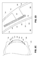
- FIG. 2A is a bottom view of an example eye-mountable device.
- FIG. 2B is an aspect view of the example eye-mountable device shown in FIG. 2A .
- FIG. 2C is a side cross-section view of the example eye-mountable device shown in FIGS. 2A and 2B while mounted to a corneal surface of an eye.
- FIG. 2D is a side cross-section view enhanced to show the tear film layers surrounding the surfaces of the example eye-mountable device when mounted as shown in FIG. 2C .
- FIG. 3 is a functional block diagram of an example system for electrochemically monitoring a tear film analyte concentration.
- FIG. 4A is a flowchart of an example process for operating an amperometric sensor in an eye-mountable device to measure a tear film analyte concentration.
- FIG. 4B is a flowchart of an example process for operating an external reader to interrogate an amperometric sensor in an eye-mountable device to measure a tear film analyte concentration.
- FIG. 5A is a cross-section view of an example container having a side-by-side configuration.
- FIG. 5B is a cross-section view of an application of a force to the container according to an example embodiment.
- FIG. 5C is a cross-section view of an application of a force to the container according to another example embodiment.
- FIG. 5D is a cross-section view of an application of a force to the container according to yet another example embodiment.
- FIG. 6 is a cross-section view of an example container having a top-bottom configuration.
- FIG. 7 is a cross-section view of an example container having a third chamber.
- FIG. 8 is a flowchart, in accordance with an example embodiment.
- a body-mountable device such as a contact lens, may be configured to monitor health-related information based on at least one analyte detected in a fluid of a user wearing the body-mountable device.
- An example body-mountable device that comprises an eye-mountable device may include an embedded sensor configured to detect an analyte in a tear film of a user wearing the eye-mountable device, such as glucose. With such an arrangement, the analyte sensor may monitor health-related information, such as glucose level or corneal oxygen concentration.
- Such an eye-mountable device may need to be hydrated, sterilized and/or calibrated before insertion into a user's eye.
- long-term storage in an aqueous solution may cause problems with the various electronic components of the eye-mountable device.
- a packing device that separates an aqueous solution from the eye-mountable device may be desirable.
- the packaging for each eye-mountable device may include a two-chamber container.
- the first chamber may include the eye-mountable device.
- the second chamber may contain an aqueous solution.
- the first and second chambers are arranged in a side-by-side configuration. In another embodiment, the first and second chambers are arranged in a top-bottom configuration.
- the aqueous solution in the second chamber may be a preconditioning solution used to hydrate the eye-mountable device before insertion into a user's eye.
- the aqueous solution may be a sterilization and/or disinfecting solution.
- the aqueous solution may be a calibration solution used to calibrate the analyte sensor on the eye-mountable device. Other potential aqueous solutions are possible as well.
- the first and second chambers may be separated by a breakable membrane.
- the membrane may include a thin polymeric material.
- the membrane may be ruptured to allow the aqueous solution to interact with the eye-mountable device.
- the membrane may be ruptured by squeezing the container.
- the membrane may be connected to a lid of the container, and the membrane may be ruptured when a user removes the lid of the container.
- the membrane may be ruptured by shaking the container. Other embodiments of rupturing the membrane are possible as well.
- FIG. 1 is a block diagram of a system 100 that includes an eye-mountable device 110 in wireless communication with an external reader 180 .
- the exposed regions of the eye-mountable device 110 are made of a polymeric material 120 formed to be contact-mounted to a corneal surface of an eye.
- a substrate 130 is embedded in the polymeric material 120 to provide a mounting surface for a power supply 140 , a controller 150 , bio-interactive electronics 160 , and a communication antenna 170 .
- the bio-interactive electronics 160 are operated by the controller 150 .
- the power supply 140 supplies operating voltages to the controller 150 and/or the bio-interactive electronics 160 .
- the antenna 170 is operated by the controller 150 to communicate information to and/or from the eye-mountable device 110 .
- the antenna 170 , the controller 150 , the power supply 140 , and the bio-interactive electronics 160 can all be situated on the embedded substrate 130 . Because the eye-mountable device 110 includes electronics and is configured to be contact-mounted to an eye, it is also referred to herein as an ophthalmic electronics platform.
- the polymeric material 120 can have a concave surface configured to adhere (“mount”) to a moistened corneal surface (e.g., by capillary forces with a tear film coating the corneal surface). Additionally or alternatively, the eye-mountable device 110 can be adhered by a vacuum force between the corneal surface and the polymeric material due to the concave curvature. While mounted with the concave surface against the eye, the outward-facing surface of the polymeric material 120 can have a convex curvature that is formed to not interfere with eye-lid motion while the eye-mountable device 110 is mounted to the eye.
- the polymeric material 120 can be a substantially transparent curved polymeric disk shaped similarly to a contact lens.
- the polymeric material 120 can include one or more bio-compatible materials, such as those employed for use in contact lenses or other ophthalmic applications involving direct contact with the corneal surface.
- the polymeric material 120 can optionally be formed in part from such bio-compatible materials or can include an outer coating with such bio-compatible materials.
- the polymeric material 120 can include materials configured to moisturize the corneal surface, such as hydrogels and the like.
- the polymeric material 120 can be a deformable (“non-rigid”) material to enhance wearer comfort.
- the polymeric material 120 can be shaped to provide a predetermined, vision-correcting optical power, such as can be provided by a contact lens.
- the substrate 130 includes one or more surfaces suitable for mounting the bio-interactive electronics 160 , the controller 150 , the power supply 140 , and the antenna 170 .
- the substrate 130 can be employed both as a mounting platform for chip-based circuitry (e.g., by flip-chip mounting) and/or as a platform for patterning conductive materials (e.g., gold, platinum, palladium, titanium, copper, aluminum, silver, metals, other conductive materials, combinations of these, etc.) to create electrodes, interconnects, antennae, etc.
- substantially transparent conductive materials e.g., indium tin oxide
- the antenna 170 can be formed by depositing a pattern of gold or another conductive material on the substrate 130 .
- interconnects 151 , 157 between the controller 150 and the bio-interactive electronics 160 , and between the controller 150 and the antenna 170 , respectively, can be formed by depositing suitable patterns of conductive materials on the substrate 130 .
- a combination of resists, masks, and deposition techniques can be employed to pattern materials on the substrate 130 .
- the substrate 130 can be a relatively rigid material, such as polyethylene terephthalate (“PET”) or another material sufficient to structurally support the circuitry and/or electronics within the polymeric material 120 .
- PET polyethylene terephthalate
- the eye-mountable device 110 can alternatively be arranged with a group of unconnected substrates rather than a single substrate.
- the controller 150 and a bio-sensor or other bio-interactive electronic component can be mounted to one substrate, while the antenna 170 is mounted to another substrate and the two can be electrically connected via the interconnects 157 .
- the bio-interactive electronics 160 (and the substrate 130 ) can be positioned away from the center of the eye-mountable device 110 and thereby avoid interference with light transmission to the eye through the center of the eye-mountable device 110 .
- the substrate 130 can be embedded around the periphery (e.g., near the outer circumference) of the disk.
- the bio-interactive electronics 160 (and the substrate 130 ) can be positioned in the center region of the eye-mountable device 110 .
- the bio-interactive electronics 160 and/or substrate 130 can be substantially transparent to incoming visible light to mitigate interference with light transmission to the eye.
- the bio-interactive electronics 160 can include a pixel array 164 that emits and/or transmits light to be perceived by the eye according to display driver instructions.
- the bio-interactive electronics 160 can optionally be positioned in the center of the eye-mountable device so as to generate perceivable visual cues to a wearer of the eye-mountable device 110 , such as by displaying information via the pixel array 164 .
- the substrate 130 can be shaped as a flattened ring with a radial width dimension sufficient to provide a mounting platform for the embedded electronics components.
- the substrate 130 can have a thickness sufficiently small to allow the substrate 130 to be embedded in the polymeric material 120 without influencing the profile of the eye-mountable device 110 .
- the substrate 130 can have a thickness sufficiently large to provide structural stability suitable for supporting the electronics mounted thereon.
- the substrate 130 can be shaped as a ring with a diameter of about 10 millimeters, a radial width of about 1 millimeter (e.g., an outer radius 1 millimeter larger than an inner radius), and a thickness of about 50 micrometers.
- the substrate 130 can optionally be aligned with the curvature of the eye-mounting surface of the eye-mountable device 110 (e.g., convex surface).
- the substrate 130 can be shaped along the surface of an imaginary cone between two circular segments that define an inner radius and an outer radius.
- the surface of the substrate 130 along the surface of the imaginary cone defines an inclined surface that is approximately aligned with the curvature of the eye mounting surface at that radius.
- the power supply 140 is configured to harvest ambient energy to power the controller 150 and bio-interactive electronics 160 .
- a radio-frequency energy-harvesting antenna 142 can capture energy from incident radio radiation.
- solar cell(s) 144 (“photovoltaic cells”) can capture energy from incoming ultraviolet, visible, and/or infrared radiation.
- an inertial power scavenging system can be included to capture energy from ambient vibrations.
- the energy harvesting antenna 142 can optionally be a dual-purpose antenna that is also used to communicate information to the external reader 180 . That is, the functions of the communication antenna 170 and the energy harvesting antenna 142 can be accomplished with the same physical antenna.
- a rectifier/regulator 146 can be used to condition the captured energy to a stable DC supply voltage 141 that is supplied to the controller 150 .
- the energy harvesting antenna 142 can receive incident radio frequency radiation. Varying electrical signals on the leads of the antenna 142 are output to the rectifier/regulator 146 .
- the rectifier/regulator 146 rectifies the varying electrical signals to a DC voltage and regulates the rectified DC voltage to a level suitable for operating the controller 150 .
- output voltage from the solar cell(s) 144 can be regulated to a level suitable for operating the controller 150 .
- the rectifier/regulator 146 can include one or more energy storage devices to mitigate high frequency variations in the ambient energy gathering antenna 142 and/or solar cell(s) 144 .
- one or more energy storage devices e.g., a capacitor, an inductor, etc.
- a capacitor, an inductor, etc. can be connected in parallel across the outputs of the rectifier 146 to regulate the DC supply voltage 141 and configured to function as a low-pass filter.
- the controller 150 is turned on when the DC supply voltage 141 is provided to the controller 150 , and the logic in the controller 150 operates the bio-interactive electronics 160 and the antenna 170 .
- the controller 150 can include logic circuitry configured to operate the bio-interactive electronics 160 so as to interact with a biological environment of the eye-mountable device 110 .
- the interaction could involve the use of one or more components, such an analyte bio-sensor 162 , in bio-interactive electronics 160 to obtain input from the biological environment. Additionally or alternatively, the interaction could involve the use of one or more components, such as pixel array 164 , to provide an output to the biological environment.
- the controller 150 includes a sensor interface module 152 that is configured to operate analyte bio-sensor 162 .
- the analyte bio-sensor 162 can be, for example, an amperometric electrochemical sensor that includes a working electrode and a reference electrode.
- a voltage can be applied between the working and reference electrodes to cause an analyte to undergo an electrochemical reaction (e.g., a reduction and/or oxidation reaction) at the working electrode.
- the electrochemical reaction can generate an amperometric current that can be measured through the working electrode.
- the amperometric current can be dependent on the analyte concentration.
- the amount of the amperometric current that is measured through the working electrode can provide an indication of analyte concentration.
- the sensor interface module 152 can be a potentiostat configured to apply a voltage difference between working and reference electrodes while measuring a current through the working electrode.
- a reagent can also be included to sensitize the electrochemical sensor to one or more desired analytes.
- a layer of glucose oxidase (“GOD”) proximal to the working electrode can catalyze glucose into hydrogen peroxide (H 2 O 2 ).
- the hydrogen peroxide can then be oxidized at the working electrode, which releases electrons to the working electrode, resulting in an amperometric current that can be measured through the working electrode.
- the current generated by either reduction or oxidation reactions is approximately proportionate to the reaction rate. Further, the reaction rate is dependent on the rate of analyte molecules reaching the electrochemical sensor electrodes to fuel the reduction or oxidation reactions, either directly or catalytically through a reagent. In a steady state, where analyte molecules diffuse to the electrochemical sensor electrodes from a sampled region at approximately the same rate that additional analyte molecules diffuse to the sampled region from surrounding regions, the reaction rate is approximately proportionate to the concentration of the analyte molecules. The current measured through the working electrode thus provides an indication of the analyte concentration.
- the controller 150 can optionally include a display driver module 154 for operating a pixel array 164 .
- the pixel array 164 can be an array of separately programmable light transmitting, light reflecting, and/or light emitting pixels arranged in rows and columns.
- the individual pixel circuits can optionally include liquid crystal technologies, microelectromechanical technologies, emissive diode technologies, etc. to selectively transmit, reflect, and/or emit light according to information from the display driver module 154 .
- Such a pixel array 164 can also optionally include more than one color of pixels (e.g., red, green, and blue pixels) to render visual content in color.
- the display driver module 154 can include, for example, one or more data lines providing programming information to the separately programmed pixels in the pixel array 164 and one or more addressing lines for setting groups of pixels to receive such programming information.
- a pixel array 164 situated on the eye can also include one or more lenses to direct light from the pixel array to a focal plane perceivable by the eye.
- the controller 150 can also include a communication circuit 156 for sending and/or receiving information via the antenna 170 .
- the communication circuit 156 can optionally include one or more oscillators, mixers, frequency injectors, etc. to modulate and/or demodulate information on a carrier frequency to be transmitted and/or received by the antenna 170 .
- the eye-mountable device 110 is configured to indicate an output from a bio-sensor by modulating an impedance of the antenna 170 in a manner that is perceivably by the external reader 180 .
- the communication circuit 156 can cause variations in the amplitude, phase, and/or frequency of backscatter radiation from the antenna 170 , and such variations can be detected by the reader 180 .
- the controller 150 is connected to the bio-interactive electronics 160 via interconnects 151 .
- a patterned conductive material e.g., gold, platinum, palladium, titanium, copper, aluminum, silver, metals, combinations of these, etc.
- the controller 150 is connected to the antenna 170 via interconnects 157 .
- FIG. 1 the block diagram shown in FIG. 1 is described in connection with functional modules for convenience in description.
- embodiments of the eye-mountable device 110 can be arranged with one or more of the functional modules (“sub-systems”) implemented in a single chip, integrated circuit, and/or physical feature.
- the rectifier/regulator 146 is illustrated in the power supply block 140
- the rectifier/regulator 146 can be implemented in a chip that also includes the logic elements of the controller 150 and/or other features of the embedded electronics in the eye-mountable device 110 .
- the DC supply voltage 141 that is provided to the controller 150 from the power supply 140 can be a supply voltage that is provided on a chip by rectifier and/or regulator components the same chip. That is, the functional blocks in FIG. 1 shown as the power supply block 140 and controller block 150 need not be implemented as separated modules.
- one or more of the functional modules described in FIG. 1 can be implemented by separately packaged chips electrically connected to one another.
- the energy harvesting antenna 142 and the communication antenna 170 can be implemented with the same physical antenna.
- a loop antenna can both harvest incident radiation for power generation and communicate information via backscatter radiation.
- the external reader 180 includes an antenna 188 (or group of more than one antennae) to send and receive wireless signals 171 to and from the eye-mountable device 110 .
- the external reader 180 also includes a computing system with a processor 186 in communication with a memory 182 .
- the memory 182 is a non-transitory computer-readable medium that can include, without limitation, magnetic disks, optical disks, organic memory, and/or any other volatile (e.g. RAM) or non-volatile (e.g. ROM) storage system readable by the processor 186 .
- the memory 182 can include a data storage 183 to store indications of data, such as sensor readings (e.g., from the analyte bio-sensor 162 ), program settings (e.g., to adjust behavior of the eye-mountable device 110 and/or external reader 180 ), etc.
- the memory 182 can also include program instructions 184 for execution by the processor 186 to cause the external reader 180 to perform processes specified by the instructions 184 .
- the program instructions 184 can cause external reader 180 to provide a user interface that allows for retrieving information communicated from the eye-mountable device 110 (e.g., sensor outputs from the analyte bio-sensor 162 ).
- the external reader 180 can also include one or more hardware components for operating the antenna 188 to send and receive the wireless signals 171 to and from the eye-mountable device 110 .
- one or more hardware components for operating the antenna 188 to send and receive the wireless signals 171 to and from the eye-mountable device 110 .
- oscillators, frequency injectors, encoders, decoders, amplifiers, filters, etc. can drive the antenna 188 according to instructions from the processor 186 .
- the external reader 180 can be a smart phone, digital assistant, or other portable computing device with wireless connectivity sufficient to provide the wireless communication link 171 .
- the external reader 180 can also be implemented as an antenna module that can be plugged in to a portable computing device, such as in an example where the communication link 171 operates at carrier frequencies not commonly employed in portable computing devices.
- the external reader 180 is a special-purpose device configured to be worn relatively near a wearer's eye to allow the wireless communication link 171 to operate with a low power budget.
- the external reader 180 can be integrated in a piece of jewelry such as a necklace, earing, etc. or integrated in an article of clothing worn near the head, such as a hat, headband, etc.
- the system 100 can be operated to monitor the analyte concentration in tear film on the surface of the eye.
- the eye-mountable device 110 can be configured as a platform for an ophthalmic analyte bio-sensor.
- the tear film is an aqueous layer secreted from the lacrimal gland to coat the eye.
- the tear film is in contact with the blood supply through capillaries in the structure of the eye and includes many biomarkers found in blood that are analyzed to characterize a person's health condition(s).
- the tear film includes glucose, calcium, sodium, cholesterol, potassium, other biomarkers, etc.
- the biomarker concentrations in the tear film can be systematically different than the corresponding concentrations of the biomarkers in the blood, but a relationship between the two concentration levels can be established to map tear film biomarker concentration values to blood concentration levels.
- the tear film concentration of glucose can be established (e.g., empirically determined) to be approximately one tenth the corresponding blood glucose concentration.
- measuring tear film analyte concentration levels provides a non-invasive technique for monitoring biomarker levels in comparison to blood sampling techniques performed by lancing a volume of blood to be analyzed outside a person's body.
- the ophthalmic analyte bio-sensor platform disclosed here can be operated substantially continuously to enable real time monitoring of analyte concentrations.
- the external reader 180 can emit radio frequency radiation 171 that is harvested to power the eye-mountable device 110 via the power supply 140 .
- Radio frequency electrical signals captured by the energy harvesting antenna 142 (and/or the communication antenna 170 ) are rectified and/or regulated in the rectifier/regulator 146 and a regulated DC supply voltage 147 is provided to the controller 150 .
- the radio frequency radiation 171 thus turns on the electronic components within the eye-mountable device 110 .
- the controller 150 operates the analyte bio-sensor 162 to measure an analyte concentration level.
- the sensor interface module 152 can apply a voltage between a working electrode and a reference electrode in the analyte bio-sensor 162 .
- the applied voltage can be sufficient to cause the analyte to undergo an electrochemical reaction at the working electrode and thereby generate an amperometric current that can be measured through the working electrode.
- the measured amperometric current can provide the sensor reading (“result”) indicative of the analyte concentration.
- the controller 150 can operate the antenna 170 to communicate the sensor reading back to the external reader 180 (e.g., via the communication circuit 156 ).
- the sensor reading can be communicated by, for example, modulating an impedance of the communication antenna 170 such that the modulation in impedance is detected by the external reader 180 .
- the modulation in antenna impedance can be detected by, for example, backscatter radiation from the antenna 170 .
- the system 100 can operate to non-continuously (“intermittently”) supply energy to the eye-mountable device 110 to power the controller 150 and electronics 160 .
- radio frequency radiation 171 can be supplied to power the eye-mountable device 110 long enough to carry out a tear film analyte concentration measurement and communicate the results.
- the supplied radio frequency radiation can provide sufficient power to apply a potential between a working electrode and a reference electrode sufficient to induce electrochemical reactions at the working electrode, measure the resulting amperometric current, and modulate the antenna impedance to adjust the backscatter radiation in a manner indicative of the measured amperometric current.
- the supplied radio frequency radiation 171 can be considered an interrogation signal from the external reader 180 to the eye-mountable device 110 to request a measurement.
- the external reader 180 can accumulate a set of analyte concentration measurements over time without continuously powering the eye-mountable device 110 .
- some embodiments of the system may include privacy controls which may be automatically implemented or controlled by the wearer of the device. For example, where a wearer's collected physiological parameter data and health state data are uploaded to a cloud computing network for trend analysis by a clinician, the data may be treated in one or more ways before it is stored or used, so that personally identifiable information is removed. For example, a user's identity may be treated so that no personally identifiable information can be determined for the user, or a user's geographic location may be generalized where location information is obtained (such as to a city, ZIP code, or state level), so that a particular location of a user cannot be determined.
- privacy controls may be automatically implemented or controlled by the wearer of the device. For example, where a wearer's collected physiological parameter data and health state data are uploaded to a cloud computing network for trend analysis by a clinician, the data may be treated in one or more ways before it is stored or used, so that personally identifiable information is removed. For example, a user's identity may be treated so that no personally identifiable information can be determined for
- wearers of a device may be provided with an opportunity to control whether or how the device collects information about the wearer (e.g., information about a user's medical history, social actions or activities, profession, a user's preferences, or a user's current location), or to control how such information may be used.
- the wearer may have control over how information is collected about him or her and used by a clinician or physician or other user of the data.
- a wearer may elect that data, such as health state and physiological parameters, collected from his or her device may only be used for generating an individual baseline and recommendations in response to collection and comparison of his or her own data and may not be used in generating a population baseline or for use in population correlation studies.
- FIG. 2A is a bottom view of an example eye-mountable device 210 .
- FIG. 2B is an aspect view of the example eye-mountable device 210 . It is noted that relative dimensions in FIGS. 2A and 2B are not necessarily to scale, but have been rendered for purposes of explanation only in describing the arrangement of the example eye-mountable device 210 .
- the eye-mountable device 210 may include a polymeric material 220 , which may be a substantially transparent material to allow incident light to be transmitted to the eye.
- the polymeric material 220 may include one or more bio-compatible materials similar to those employed to form vision correction and/or cosmetic contact lenses in optometry, such as polyethylene terephthalate (“PET”), polymethyl methacrylate (“PMMA”), polyhydroxyethylmethacrylate (“polyHEMA”), silicone hydrogels, or any combinations of these. Other polymeric materials may also be envisioned.
- the polymeric material 220 may include materials configured to moisturize the corneal surface, such as hydrogels and the like. In some embodiments, the polymeric material 220 is a deformable (“non-rigid”) material to enhance wearer comfort.
- the eye-mountable device 210 may comprise a concave surface 226 configured to adhere (“mount”) to a moistened corneal surface (e.g., by capillary forces with a tear film coating the corneal surface).
- the bottom view in FIG. 2A faces the concave surface 226 .
- a convex surface 224 of eye-mountable device 210 is formed so as not to interfere with eye-lid motion while the eye-mountable device 210 is mounted to the eye. From the bottom view shown in FIG.
- an outer periphery 222 near the outer circumference of the eye-mountable device 210 has a concave curve shape, whereas a central region 221 , near the center of the eye-mountable device 210 , has a convex curve shape.
- the eye-mountable device 210 can have dimensions similar to a vision correction and/or cosmetic contact lenses, such as a diameter of approximately 1 centimeter, and a thickness of about 0.1 to about 0.5 millimeters. However, the diameter and thickness values are provided for explanatory purposes only. In some embodiments, the dimensions of the eye-mountable device 210 may be selected according to the size and/or shape of the corneal surface of the wearer's eye. In some embodiments, the eye-mountable device 210 is shaped to provide a predetermined, vision-correcting optical power, such as provided by a prescription contact lens.
- a sensing platform 230 is embedded in the eye-mountable device 210 .
- the sensing platform 230 can be embedded to be situated near or along the outer periphery 222 , away from the central region 221 . Such a position ensures that the sensing platform 230 will not interfere with a wearer's vision when the eye-mountable device 210 is mounted on a wearer's eye, because it is positioned away from the central region 221 where incident light is transmitted to the eye-sensing portions of the eye.
- portions of the sensing platform 230 can be formed of a transparent material to further mitigate effects on visual perception.
- the sensing platform 230 may be shaped as a flat, circular ring (e.g., a disk with a centered hole).
- the flat surface of the sensing platform 230 (e.g., along the radial width) allows for mounting electronics such as chips (e.g., via flip-chip mounting) and for patterning conductive materials to form electrodes, antenna(e), and/or interconnections.
- the sensing platform 230 and the polymeric material 220 may be approximately cylindrically symmetric about a common central axis.
- the sensing platform 230 may have, for example, a diameter of about 10 millimeters, a radial width of about 1 millimeter (e.g., an outer radius 1 millimeter greater than an inner radius), and a thickness of about 50 micrometers. These dimensions are provided for example purposes only, and in no way limit the present disclosure.
- a loop antenna 270 , controller 250 , and bio-interactive electronics 260 are included in the sensing platform 230 .
- the controller 250 may be a chip including logic elements configured to operate the bio-interactive electronics 260 and the loop antenna 270 , and may be the same as or similar to the controller 150 discussed in connection with FIG. 1 .
- the controller 250 is electrically connected to the loop antenna 270 by interconnects 257 also situated on the substrate 230 .
- the controller 250 is electrically connected to the bio-interactive electronics 260 by an interconnect 251 .
- the interconnects 251 , 257 , the loop antenna 270 , and any conductive electrodes may be formed from any type of conductive material and may be patterned by any process that be used for patterning such materials, such as deposition or photolithography, for example.
- the conductive materials patterned on the substrate 230 may be, for example, gold, platinum, palladium, titanium, carbon, aluminum, copper, silver, silver-chloride, conductors formed from noble materials, metals, or any combinations of these materials. Other materials may also be envisioned.
- the bio-interactive electronics module 260 is on a side of the sensing platform 230 facing the convex surface 224 .
- the bio-interactive electronics module 260 includes an analyte bio-sensor, for example, mounting such a bio-sensor on the sensing platform 230 to be close to the convex surface 224 allows the bio-sensor to sense analyte that has diffused through convex surface 224 or has reached the bio-sensor through a channel in the convex surface 224 ( FIGS. 2C and 2D show a channel 272 ).
- the loop antenna 270 is a layer of conductive material patterned along the flat surface of the substrate 230 to form a flat conductive ring.
- the loop antenna 270 may be the same as or similar to the antenna 170 described in connection with FIG. 1 .
- the loop antenna 270 does not form a complete loop.
- the loop antenna 270 may include a cutout to allow room for the controller 250 and bio-interactive electronics 260 , as illustrated in FIG. 2A .
- the loop antenna 270 can be arranged as a continuous strip of conductive material that wraps entirely around the sensing platform 230 one or more times. Interconnects between the ends of such a wound antenna (e.g., the antenna leads) can connect to the controller 250 in the sensing platform 230 .
- the sensing platform 230 may be a bio-compatible structure in which some or all of the components are encapsulated by a bio-compatible material.
- controller 250 , interconnects 251 , 257 , bio-interactive electronics 260 , and antenna 270 are fully encapsulated by bio-compatible material, except for the sensor electrodes in the bio-interactive electronics 260 .
- FIG. 2C is a side cross-section view of the example eye-mountable electronic device 210 mounted to a corneal surface 284 of an eye 280 .
- FIG. 2D is an enlarged partial view the cross-section of the example eye-mountable device shown in FIG. 2C . It is noted that relative dimensions in FIGS. 2C and 2D are not necessarily to scale, but have been rendered for purposes of explanation only in describing the arrangement of the example eye-mountable electronic device 210 . Some aspects are exaggerated to allow for illustration and to facilitate explanation.
- the eye 280 includes a cornea 282 that is covered by bringing an upper eyelid 286 and a lower eyelid 288 together over the surface of the eye 280 .
- Incident light is received by the eye 280 through the cornea 282 , where light is optically directed to light sensing elements of the eye 280 to stimulate visual perception.
- the motion of the upper and lower eyelids 286 , 288 distributes a tear film across the exposed corneal surface 284 of the eye 280 .
- the tear film is an aqueous solution secreted by the lacrimal gland to protect and lubricate the eye 280 .
- the tear film coats both the concave and convex surfaces 224 , 226 , providing an inner layer 290 (along the concave surface 226 ) and an outer layer 292 (along the convex surface 224 ).
- the inner layer 290 on the corneal surface 284 also facilitates mounting the eye-mountable device 210 by capillary forces between the concave surface 226 and the corneal surface 284 .
- the eye-mountable device 210 can also be held over the eye 280 in part by vacuum forces against the corneal surface 284 due to the curvature of the concave surface 226 .
- the tear film layers 290 , 292 may be about 10 micrometers in thickness and together account for about 10 microliters of fluid.
- the tear film is in contact with the blood supply through capillaries in the structure of the eye and includes many biomarkers found in blood that are analyzed to diagnose health states of an individual.
- tear film includes glucose, calcium, sodium, cholesterol, potassium, other biomarkers, etc.
- the biomarker concentrations in tear film can be systematically different than the corresponding concentrations of the biomarkers in the blood, but a relationship between the two concentration levels can be established to map tear film biomarker concentration values to blood concentration levels.
- the tear film concentration of glucose can be established (e.g., empirically determined) to be approximately one tenth the corresponding blood glucose concentration.
- another ratio relationship and/or a non-ratio relationship may be used.
- measuring tear film analyte concentration levels provides a non-invasive technique for monitoring biomarker levels in comparison to blood sampling techniques performed by lancing a volume of blood to be analyzed outside a person's body.
- the sensing platform 230 can be inclined so as to be approximately parallel to the adjacent portion of the convex surface 224 .
- the sensing platform 230 is a flattened ring with an inward-facing surface 232 (closer to the concave surface 226 of the polymeric material 220 ) and an outward-facing surface 234 (closer to the convex surface 224 ).
- the sensing platform 230 can include electronic components and/or patterned conductive materials adjacent to either or both surfaces 232 , 234 .
- the bio-interactive electronics 260 , the controller 250 , and the conductive interconnect 251 are mounted on the outward-facing surface 234 such that the bio-interactive electronics 260 are facing the convex surface 224 .
- the bio-interactive electronics 260 can receive analyte concentrations in the tear film 292 through the channel 272 .
- the bio-interactive electronics 260 may be mounted on the inward-facing surface 232 of the sensing platform 230 such that the bio-interactive electronics 260 are facing the concave surface 226 .
- FIG. 3 is a functional block diagram of a system 300 for electrochemically measuring a tear film analyte concentration.
- the system 300 includes an eye-mountable device 310 with embedded electronic components powered by an external reader 340 .
- the eye-mountable device 310 includes an antenna 312 for capturing radio frequency radiation 341 from the external reader 340 .
- the eye-mountable device 310 includes a rectifier 314 , an energy storage 316 , and regulator 318 for generating power supply voltages 330 , 332 to operate the embedded electronics.
- the eye-mountable device 310 includes an electrochemical sensor 320 with a working electrode 322 and a reference electrode 323 driven by a sensor interface 321 .
- the eye-mountable device 310 includes hardware logic 324 for communicating results from the sensor 320 to the external reader 340 by modulating ( 325 ) the impedance of the antenna 312 . Similar to the eye-mountable devices 110 , 210 discussed above in connection with FIGS. 1 and 2 , the eye-mountable device 310 can include a mounting substrate embedded within a polymeric material configured to be mounted to an eye.
- the electrochemical sensor 320 can be situated on a mounting surface of such a substrate proximate the surface of the eye (e.g., corresponding to the bio-interactive electronics 260 on the inward-facing side 232 of the substrate 230 ) to measure analyte concentration in a tear film layer interposed between the eye-mountable device 310 and the eye (e.g., the inner tear film layer 40 between the eye-mountable device 210 and the corneal surface 22 ).
- the electrochemical sensor 320 measures analyte concentration by applying a voltage between the electrodes 322 , 323 that is sufficient to cause products of the analyte catalyzed by the reagent to electrochemically react (e.g., a reduction and/or oxidization reaction) at the working electrode 322 .
- the electrochemical reactions at the working electrode 322 generate an amperometric current that can be measured at the working electrode 322 .
- the sensor interface 321 can, for example, apply a reduction voltage between the working electrode 322 and the reference electrode 323 to reduce products from the reagent-catalyzed analyte at the working electrode 322 .
- the sensor interface 321 can apply an oxidization voltage between the working electrode 322 and the reference electrode 323 to oxidize the products from the reagent-catalyzed analyte at the working electrode 322 .
- the sensor interface 321 measures the amperometric current and provides an output to the hardware logic 324 .
- the sensor interface 321 can include, for example, a potentiostat connected to both electrodes 322 , 323 to simultaneously apply a voltage between the working electrode 322 and the reference electrode 323 and measure the resulting amperometric current through the working electrode 322 .
- the rectifier 314 , energy storage 316 , and voltage regulator 318 operate to harvest energy from received radio frequency radiation 341 .
- the radio frequency radiation 341 causes radio frequency electrical signals on leads of the antenna 312 .
- the rectifier 314 is connected to the antenna leads and converts the radio frequency electrical signals to a DC voltage.
- the energy storage 316 e.g., capacitor
- the regulator 318 receives the filtered DC voltage and outputs both a digital supply voltage 330 to operate the hardware logic 324 and an analog supply voltage 332 to operate the electrochemical sensor 320 .
- the analog supply voltage can be a voltage used by the sensor interface 321 to apply a voltage between the sensor electrodes 322 , 323 to generate an amperometric current.
- the digital supply voltage 330 can be a voltage suitable for driving digital logic circuitry, such as approximately 1.2 volts, approximately 3 volts, etc. Reception of the radio frequency radiation 341 from the external reader 340 (or another source, such as ambient radiation, etc.) causes the supply voltages 330 , 332 to be supplied to the sensor 320 and hardware logic 324 . While powered, the sensor 320 and hardware logic 324 are configured to generate and measure an amperometric current and communicate the results.
- the sensor results can be communicated back to the external reader 340 via backscatter radiation 343 from the antenna 312 .
- the hardware logic 324 receives the output current from the electrochemical sensor 320 and modulates ( 325 ) the impedance of the antenna 312 in accordance with the amperometric current measured by the sensor 320 .
- the antenna impedance and/or change in antenna impedance is detected by the external reader 340 via the backscatter signal 343 .
- the external reader 340 can include an antenna front end 342 and logic components 344 to decode the information indicated by the backscatter signal 343 and provide digital inputs to a processing system 346 .
- the external reader 340 associates the backscatter signal 343 with the sensor result (e.g., via the processing system 346 according to a pre-programmed relationship associating impedance of the antenna 312 with output from the sensor 320 ).
- the processing system 346 can then store the indicated sensor results (e.g., tear film analyte concentration values) in a local memory and/or a network-connected memory.
- one or more of the features shown as separate functional blocks can be implemented (“packaged”) on a single chip.
- the eye-mountable device 310 can be implemented with the rectifier 314 , energy storage 316 , voltage regulator 318 , sensor interface 321 , and the hardware logic 324 packaged together in a single chip or controller module.
- Such a controller can have interconnects (“leads”) connected to the loop antenna 312 and the sensor electrodes 322 , 323 .
- Such a controller operates to harvest energy received at the loop antenna 312 , apply a voltage between the electrodes 322 , 323 sufficient to develop an amperometric current, measure the amperometric current, and indicate the measured current via the antenna 312 (e.g., through the backscatter radiation 343 ).
- FIG. 4A is a flowchart of a process 400 for operating an amperometric sensor in an eye-mountable device to measure a tear film analyte concentration.
- Radio frequency radiation is received at an antenna in an eye-mountable device including an embedded electrochemical sensor ( 402 ).
- Electrical signals due to the received radiation are rectified and regulated to power the electrochemical sensor and associated controller ( 404 ).
- a rectifier and/or regulator can be connected to the antenna leads to output a DC supply voltage for powering the electrochemical sensor and/or controller.
- a voltage sufficient to cause electrochemical reactions at the working electrode is applied between a working electrode and a reference electrode on the electrochemical sensor ( 406 ).
- An amperometric current is measured through the working electrode ( 408 ).
- a potentiostat can apply a voltage between the working and reference electrodes while measuring the resulting amperometric current through the working electrode.
- the measured amperometric current is wirelessly indicated with the antenna ( 410 ).
- backscatter radiation can be manipulated to indicate the sensor result by modulating the antenna impedance.
- FIG. 4B is a flowchart of a process 420 for operating an external reader to interrogate an amperometric sensor in an eye-mountable device to measure a tear film analyte concentration.
- Radio frequency radiation is transmitted to an electrochemical sensor mounted in an eye from the external reader ( 422 ).
- the transmitted radiation is sufficient to power the electrochemical sensor with energy from the radiation for long enough to perform a measurement and communicate the results ( 422 ).
- the radio frequency radiation used to power the electrochemical sensor can be similar to the radiation 341 transmitted from the external reader 340 to the eye-mountable device 310 described in connection with FIG. 3 above.
- the external reader then receives backscatter radiation indicating the measurement by the electrochemical analyte sensor ( 424 ).
- the backscatter radiation can be similar to the backscatter signals 343 sent from the eye-mountable device 310 to the external reader 340 described in connection with FIG. 3 above.
- the backscatter radiation received at the external reader is then associated with a tear film analyte concentration ( 426 ).
- the analyte concentration values can be stored in the external reader memory (e.g., in the processing system 346 ) and/or a network-connected data storage.
- the sensor result (e.g., the measured amperometric current) can be encoded in the backscatter radiation by modulating the impedance of the backscattering antenna.
- the external reader can detect the antenna impedance and/or change in antenna impedance based on a frequency, amplitude, and/or phase shift in the backscatter radiation.
- the sensor result can then be extracted by associating the impedance value with the sensor result by reversing the encoding routine employed within the eye-mountable device.
- the reader can map a detected antenna impedance value to an amperometric current value.
- the amperometric current value is approximately proportionate to the tear film analyte concentration with a sensitivity (e.g., scaling factor) relating the amperometric current and the associated tear film analyte concentration.
- the sensitivity value can be determined in part according to empirically derived calibration factors, for example.
- body-mountable device has been described as comprising the eye-mountable device 110 , 210 , 310 , the body-mountable device could comprise other mountable devices that are mounted on or in other portions of the human body.
- the body-mountable device may comprise a tooth-mountable device.
- the tooth-mountable device may take the form of or be similar in form to the eye-mountable device 110 and/or the eye-mountable device 310 .
- the tooth-mountable device could include a polymeric material or a transparent polymer that is the same or similar to any of the polymeric materials or transparent polymers described herein and a substrate or a structure that is the same or similar to any of the substrates or structures described herein.
- the tooth-mountable device may be configured to detect at least one analyte in a fluid (e.g., saliva) of a user wearing the tooth-mountable device.
- a fluid e.g., saliva
- the body-mountable device may comprise a skin-mountable device.
- the skin-mountable device may take the form of or be similar in form to the eye-mountable device 110 and/or the eye-mountable device 310 .
- the skin-mountable device could include a polymeric material or a transparent polymer that is the same or similar to any of the polymeric materials or transparent polymers described herein and a substrate or a structure that is the same or similar to any of the substrates or structures described herein.
- the skin-mountable device may be configured to detect at least one analyte in a fluid (e.g., perspiration, blood, etc.) of a user wearing the skin-mountable device.
- a fluid e.g., perspiration, blood, etc.
- An eye-mountable device such as the device described above, may need to be hydrated, sterilized, and/or calibrated before insertion into a user's eye.
- long-term storage in an aqueous solution may cause problems with the various electronic components of the eye-mountable device.
- a container that separates an aqueous solution from the eye-mountable device may be desirable.
- FIG. 5A illustrates a cross-section view of an example embodiment of a container 500 .
- the container 500 may include a first chamber 502 and a second chamber 504 .
- the first chamber 502 and the second chamber 504 may be arranged in a side-by-side configuration.
- the first chamber 502 may include an eye-mountable device 506
- the second chamber 504 may contain an aqueous solution 508 .
- the eye-mountable device 506 may be similar to the eye-mountable devices 110 , 210 , 310 discussed above in connection with FIGS. 1 - 3 above and may include an analyte sensor embedded within a polymeric material configured to be contact-mounted to an eye.
- the aqueous solution 508 may be a preconditioning solution used to hydrate the eye-mountable device 506 before insertion into a user's eye.
- the aqueous solution 508 may be a sterilization and/or a disinfecting solution used to clean the eye-mountable device 506 of any debris that has accumulated on the device during shipment and storage.
- the aqueous solution 508 may be a multipurpose solution used to hydrate and sterilize the eye-mountable device 506 before insertion into a user's eye.
- the eye-mountable device 506 may include an analyte sensor embedded in the eye-mountable device 506 .
- the aqueous solution 508 may be a calibration solution used to calibrate the analyte sensor.
- the analyte sensor embedded in the eye-mountable device 506 can be exposed to the calibration solution having a known analyte concentration and a sensor reading may be obtained while the analyte sensor remains exposed.
- the sensor result (e.g., the amperometric current) divided by the concentration of the analyte can be set as the sensitivity of the ophthalmic sensing platform, and a linear relationship can be established with the sensitivity as the slope to relate future and/or past sensor results to analyte concentrations.
- a technique can be used to determine a functional relationship relating the amperometric current and the concentration of analyte using only one calibration data point. For example, a single calibration data point (e.g., sensor result while the sensor is exposed to the calibration solution with a known analyte concentration paired with the known analyte concentration) can be used in combination with assumptions and/or previous calibration data to determine a functional relationship relating sensor results to analyte concentrations.
- the functional form can be determined by solving for a linear relationship that passes through the calibration data point and the origin. Thus, the relationship is assumed to be linear, and a zero current reading is assumed to correspond to an analyte concentration of zero. The determination of the relationship then amounts to solving for the slope of such a linear relationship where the intercept is held fixed (e.g., at zero).
- the slope of the linear relationship is therefore the sensitivity of the eye-mountable analyte sensor: ACcal I Ical.
- the intercept can be assumed to be another value other than zero while still solving for the slope of a linear relationship.
- an analyte concentration of zero can still register a low level amperometric current due to, for example, ions, enzymes, etc. that electrochemically react with the sensor even in the absence of the analyte.
- a linear relationship can be determined by using the calibration data point to solve for an intercept value (e.g., current level for zero analyte concentration) of a linear relationship while keeping the slope (e.g., sensitivity) of the relationship fixed.
- an intercept value e.g., current level for zero analyte concentration
- the slope e.g., sensitivity
- the container 500 may also include a membrane 510 positioned between the first chamber 502 and the second chamber 504 .
- the membrane 510 may include a thin polymeric material.
- the polymeric material may include polyolefin. Other materials are possible as well.
- the thickness of the membrane 510 is less than about 250 micrometers or may be other thicknesses greater than 250 micrometers depending on a scale/size of the container 500 .
- the container 500 may also include external surfaces 512 that define the general shape of the container 500 . In FIG. 5A , the external surfaces 512 are shown in a semi-elliptical shape. In another embodiment, the external surfaces may be hemispherical or rectangular in shape. Other shapes are possible as well.
- the external surfaces 512 may include a polymer material.
- the polymeric material of the external surfaces 512 may be the same or different than the polymeric material of the membrane 510 .
- the thickness of the external surfaces 512 of the container 500 may be at least 10 times greater than the thickness of the membrane 510 .
- the external surfaces 512 on the container 500 may be more rigid than the membrane 510 , so as to protect the eye-mountable device 506 from forces applied during shipment and storage.
- the container may also include a lid 514 configured to seal one or more of the first chamber 502 and the second chamber 504 .
- the lid 514 may include a polyester spin cast woven fabric, although other materials are possible as well.
- the lid 514 may be connected to the membrane 510 .
- the lid 514 is configured to be removed by a user to access the eye-mountable device 506 .
- the lid 514 ensures that the eye-mountable device 506 and aqueous solution 508 remain sealed in the container 500 during shipment and storage.
- the membrane 510 is configured to rupture based on the application of a force to the container 500 .
- the ruptured membrane 510 allows the aqueous solution 508 to engage with the eye-mountable device 506 to hydrate, sanitize and/or calibrate the eye-mountable device 506 before insertion into a user's eye, as discussed above.
- the membrane 510 may be pre-stressed so as to weaken the membrane and therefore make it easier for a user to rupture the membrane. For example, a tensile stress may be applied to the membrane 510 during fabrication of the container 500 . Other examples are possible as well.
- the membrane 510 may be ruptured by squeezing the container 500 .
- FIGS. 5B and 5C illustrate examples of such an embodiment.
- a force 516 is applied to the second chamber 504 of the container 500 .
- the arrows denoting the force 516 may represent the index finger and the thumb of a user who squeezes the container 500 .
- the force 516 is applied to the second chamber 504
- the pressure in the second chamber 504 increases, causing the membrane 510 to expand towards the first chamber 502 .
- a critical value of force 516 is applied, the membrane 510 will rupture, allowing the aqueous solution 508 to engage with the eye-mountable device 506 .
- FIG. 5C illustrates a similar embodiment, except the force 518 is applied to the first chamber 502 of the container 500 .
- the force 518 is applied to the first chamber 502 , the pressure in the first chamber 502 increases, causing the membrane 510 to expand.
- a critical value of force 518 is applied, the membrane 510 will rupture, allowing the aqueous solution 508 to engage with the eye-mountable device 506 .
- the critical force may be a value greater than those forces typically experienced in shipment and storage, but less than about 25 Newtons.
- the membrane 510 may be connected to the lid 514 of the container 500 , and the membrane 510 may be ruptured when a user removes the lid 514 .
- FIG. 5D illustrates such an embodiment.
- the membrane 510 may remain connected to the lid 514 and become disconnected from the bottom external surface 512 of the container 500 .
- the ruptured membrane 510 allows the aqueous solution 508 to engage with the eye-mountable device 506 .
- an adhesive may be used to connect the membrane 510 to the lid 514 .
- the lid 514 and the membrane 510 may be fabricated together as one piece.
- the membrane 510 may be perforated so that when the lid 514 is removed, the membrane 510 ruptures at the perforation. Other embodiments are possible as well.
- the membrane 510 may be ruptured by shaking the container 500 .
- the act of shaking the container 500 may increase the pressure in one or more of the first chamber 502 and the second chamber 504 , thereby applying a force to the membrane 510 .
- the membrane 510 will rupture, allowing the aqueous solution 508 to engage with the eye-mountable device 506 .
- a user may remove the lid 514 , and then remove the membrane 510 by hand.
- the membrane 510 may be perforated and the user may rupture the membrane 510 by tearing the perforation.
- the user may simply peel away the membrane 510 after removing the lid 514 to allow the aqueous solution 508 to engage with the eye-mountable device 506 .
- Other embodiments of applying a force to rupture the membrane are possible as well.
- FIG. 6 illustrates a cross-section view of another embodiment of a container 600 .
- the first chamber 602 and the second chamber 604 are arranged in a top-bottom configuration.
- the first chamber 602 may include an eye-mountable device 606
- the second chamber 604 may include an aqueous solution 608 .
- the eye-mountable device 606 may be similar to the eye-mountable devices 110 , 210 , 310 discussed above in connection with FIGS. 1-3 above and may include an analyte sensor embedded within a polymeric material configured to be contact-mounted to an eye.
- the container 600 may also include a membrane 610 positioned between the first chamber 602 and the second chamber 604 and may also include external surfaces 612 that define the general shape of the container 600 .
- the container 600 may also include a lid 614 configured to seal the first chamber 602 .
- the membrane 610 may be configured to rupture based on the application of a force to the container 600 .
- the membrane 610 may be ruptured by squeezing the container 600 or by shaking the container 600 , as described above.
- the membrane 610 may be connected to the lid 614 of the container 600 , and the membrane 610 may be ruptured when a user removes the lid 614 .
- Other embodiments of applying a force to rupture the membrane are possible as well.
- the second chamber 604 containing the aqueous solution 608 may be positioned below the first chamber 602 containing the eye-mountable device 606 .
- the first chamber 602 may be positioned below the second chamber 604 .
- FIG. 7 illustrates a cross-section view of another embodiment of a container 700 .
- the container 700 may include a first chamber 702 , a second chamber 704 , and a third chamber 706 .
- the first chamber 702 may include a first aqueous solution 708
- the second chamber may contain an eye-mountable device 710
- the third chamber 706 may contain a second aqueous solution 712 .
- the eye-mountable device 710 may be similar to the eye-mountable devices 110 , 210 , 310 , 506 discussed above in connection with FIGS. 1-3 , and 5 above and may include an analyte sensor embedded within a polymeric material configured to be contact-mounted to an eye.
- the first aqueous solution 708 may be a preconditioning solution used to hydrate the eye-mountable device 710 before insertion into a user's eye.
- the first aqueous solution 708 may be a sterilization and/or a disinfecting solution used to clean the eye-mountable device 710 of any debris that has accumulated on the device during shipment and storage.
- the first aqueous solution 708 may be a multipurpose solution used to hydrate and sterilize the eye-mountable device 710 before insertion into a user's eye.
- the second aqueous solution 712 may be the same as the first solution 708 . In another embodiment, the second aqueous solution 712 may be different than the first solution 708 .
- the container 700 may also include a first membrane 714 positioned between the first chamber 702 and the second chamber 704 , and a second membrane 716 positioned between the second chamber 704 and the third chamber 706 .
- the first membrane 714 may include a thin polymeric material.
- the polymeric material may include polyolefin. Other materials are possible as well.
- the second membrane 716 may include the same material as the first membrane 714 . In another example, the second membrane 716 may include different materials than the first membrane 716 .
- the container 700 may also include external surfaces 718 that define the general shape of the container 700 .
- the container 700 may also include a lid 720 configured to seal the container 700 .
- the first membrane 714 and/or the second membrane 716 may be configured to rupture based on the application of a force to the container 700 .
- the first membrane 714 and/or the second membrane 716 may be ruptured by squeezing the container 700 or by shaking the container 700 , as described above.
- the first membrane 714 and/or the second membrane 716 may be connected to the lid 720 of the container 700 , and the first membrane 714 and/or the second membrane 716 may be ruptured when a user removes the lid 720 .
- Other embodiments of applying a force to rupture the membrane are possible as well.
- FIG. 8 depicts a flowchart of an example method.
- Method 800 may include one or more operations, functions, or actions as illustrated by one or more of blocks 802 - 810 . Although the blocks are illustrated in a sequential order, these blocks may also be performed in parallel, and/or in a different order than those described herein. Also, the various blocks may be combined into fewer blocks, divided into additional blocks, and/or removed based upon the desired implementation.
- a body-mountable device comprises an eye-mountable device. It should be understood, however, that the method 800 may involve scenarios where the body-mountable device comprises other mountable devices that are mounted to other portions of the human body. For example, method 800 may involve scenarios where the body-mountable device comprises a tooth-mountable device and/or a skin mountable device.
- the method includes providing a container having an opening.
- providing the container with an opening may include forming the container through cast molding by compressing molding material between molding cavities.
- the molding material may include a polymeric material such as polyolefin, although other materials are possible as well.
- the container may be formed via injection molding. In injection molding, molding material may be heated and injected or otherwise forced into a molding cavity or cavities. The injected molding material may then cool and harden to the configuration of the molding cavity or cavities.
- the container may be formed via spin casting. Through spin-casting techniques, a fabrication device may form a container having a precise thickness.
- a spin-casting mold may be spun along its central access at a set speed, and the molding material may be introduced to the mold as the mold is spinning in order to form the container.
- the final thickness of the container may be influenced by various factors, including but not limited to the spin-casting mold, the amount of molding material introduced to the spin-casting mold, properties of the molding material such as viscosity, and/or the speed at which the spin-casting mold is rotated. These factors may be varied in order to result in a container of a well-defined thickness.
- the container may be formed via thermoforming. Through thermoforming, a sheet of polymeric material is heated to a pliable forming temperature. The heated polymeric material may then be formed to a specific shape in a mold, and trimmed to create a usable container. Other embodiments are possible as well.
- the method includes providing an eye-mountable device in a first chamber of the container.
- the eye-mountable device may be similar to the eye-mountable devices 110 , 210 , 310 discussed above in connection with FIGS. 1-3 above and may include an analyte sensor embedded within a polymeric material configured to be contact-mounted to an eye.
- the method includes providing an aqueous solution in a second chamber of the container.
- the aqueous solution may be a preconditioning solution used to hydrate the eye-mountable device before insertion into a user's eye.
- the aqueous solution may be a sterilization and/or a disinfecting solution used to clean the eye-mountable device 506 of any debris that has accumulated on the device during shipment and storage.
- the aqueous solution may be a multipurpose solution used to hydrate and sterilize the eye-mountable device before insertion into a user's eye.
- the aqueous solution may be a calibration solution having a known analyte concentration which may be used to calibrate an analyte sensor embedded in the eye-mountable device. Other aqueous solutions are possible as well.
- the method includes providing a membrane to divide the container into the first chamber and the second chamber, wherein the membrane is configured to rupture based on application of a force to the container.
- the ruptured membrane enables the aqueous solution to engage with the eye-mountable device.
- the membrane may include a thin polymeric material, such as polyolefin. Other materials are possible as well. In one embodiment, the thickness of the membrane is less than about 100 micrometers. The ruptured membrane allows the aqueous solution to engage with the eye-mountable device to hydrate, sanitize and/or calibrate the eye-mountable device before insertion into a user's eye, as discussed above.
- the membrane may be pre-stressed so as to weaken the membrane and therefore make it easier for a user to rupture the membrane.
- a tensile stress may be applied to the membrane during fabrication of the container. Other examples are possible as well.
- the membrane may be ruptured by squeezing the container, as discussed above in relation to FIGS. 5B and 5C .
- the membrane may be connected to a lid of the container, and the membrane may be ruptured when a user removes the lid, as discussed above in relation to FIG. 5D .
- the membrane may be ruptured by shaking the container. Other embodiments of applying a force to rupture the membrane are possible as well.
- the method includes providing a lid configured to seal the opening of the container.
- the lid may include a polyester spin cast woven fabric, although other materials are possible as well.
- the lid may be connected to the membrane.
- the lid is configured to be removed by a user to access the eye-mountable device. The lid ensures that the eye-mountable device and aqueous solution remain sealed in the container during shipment and storage.
- Some embodiments may include privacy controls.
- privacy controls may include, at least, anonymization of device identifiers, transparency and user controls, including functionality that would enable users to modify or delete information relating to the user's use of a product.
- the users may be provided with an opportunity to control whether programs or features collect user information (e.g., information about a user's medical history, social network, social actions or activities, profession, a user's preferences, or a user's current location), or to control whether and/or how to receive content from the content server that may be more relevant to the user.
- user information e.g., information about a user's medical history, social network, social actions or activities, profession, a user's preferences, or a user's current location
- certain data may be treated in one or more ways before it is stored or used, so that personally identifiable information is removed.
- a user's identity may be treated so that no personally identifiable information can be determined for the user, or a user's geographic location may be generalized where location information is obtained (such as to a city, ZIP code, or state level), so that a particular location of a user cannot be determined.
- location information such as to a city, ZIP code, or state level
- the user may have control over how information is collected about the user and used by a content server.
Landscapes
- Health & Medical Sciences (AREA)
- Life Sciences & Earth Sciences (AREA)
- Engineering & Computer Science (AREA)
- Physics & Mathematics (AREA)
- Mechanical Engineering (AREA)
- Heart & Thoracic Surgery (AREA)
- Pathology (AREA)
- Biomedical Technology (AREA)
- Biophysics (AREA)
- Medical Informatics (AREA)
- Molecular Biology (AREA)
- Surgery (AREA)
- Animal Behavior & Ethology (AREA)
- General Health & Medical Sciences (AREA)
- Public Health (AREA)
- Veterinary Medicine (AREA)
- Optics & Photonics (AREA)
- Eye Examination Apparatus (AREA)
Abstract
Description
glucose+O2 G→ODH2O2+gluconolactone
H2O2→2H++O2+2e −
AC=f(Imeas)=(ACcal/Ical)Imeas,
where ACcal is the analyte concentration of the calibration solution, and Ical is the sensor current measured while the eye-mountable analyte sensor is exposed the calibration solution. The slope of the linear relationship is therefore the sensitivity of the eye-mountable analyte sensor: ACcal I Ical. It is noted that the intercept can be assumed to be another value other than zero while still solving for the slope of a linear relationship. For example, an analyte concentration of zero can still register a low level amperometric current due to, for example, ions, enzymes, etc. that electrochemically react with the sensor even in the absence of the analyte. Moreover, in some embodiments, a linear relationship can be determined by using the calibration data point to solve for an intercept value (e.g., current level for zero analyte concentration) of a linear relationship while keeping the slope (e.g., sensitivity) of the relationship fixed. Other potential aqueous solutions are possible as well.
Claims (19)
Priority Applications (1)
| Application Number | Priority Date | Filing Date | Title |
|---|---|---|---|
| US14/035,696 US8881892B1 (en) | 2013-06-24 | 2013-09-24 | Container |
Applications Claiming Priority (2)
| Application Number | Priority Date | Filing Date | Title |
|---|---|---|---|
| US13/924,911 US9044075B2 (en) | 2013-06-24 | 2013-06-24 | Container |
| US14/035,696 US8881892B1 (en) | 2013-06-24 | 2013-09-24 | Container |
Related Parent Applications (1)
| Application Number | Title | Priority Date | Filing Date |
|---|---|---|---|
| US13/924,911 Continuation US9044075B2 (en) | 2013-06-24 | 2013-06-24 | Container |
Publications (1)
| Publication Number | Publication Date |
|---|---|
| US8881892B1 true US8881892B1 (en) | 2014-11-11 |
Family
ID=51845659
Family Applications (2)
| Application Number | Title | Priority Date | Filing Date |
|---|---|---|---|
| US13/924,911 Expired - Fee Related US9044075B2 (en) | 2013-06-24 | 2013-06-24 | Container |
| US14/035,696 Expired - Fee Related US8881892B1 (en) | 2013-06-24 | 2013-09-24 | Container |
Family Applications Before (1)
| Application Number | Title | Priority Date | Filing Date |
|---|---|---|---|
| US13/924,911 Expired - Fee Related US9044075B2 (en) | 2013-06-24 | 2013-06-24 | Container |
Country Status (3)
| Country | Link |
|---|---|
| US (2) | US9044075B2 (en) |
| EP (1) | EP3013177B1 (en) |
| WO (1) | WO2014209998A1 (en) |
Cited By (12)
| Publication number | Priority date | Publication date | Assignee | Title |
|---|---|---|---|---|
| US20150173474A1 (en) * | 2013-12-19 | 2015-06-25 | Google Inc. | Packaging for an Active Contact Lens |
| US9696564B1 (en) | 2012-08-21 | 2017-07-04 | Verily Life Sciences Llc | Contact lens with metal portion and polymer layer having indentations |
| WO2017168122A1 (en) * | 2016-03-28 | 2017-10-05 | Coopervision International Holding Company, Lp | Contact lens blister package, base member for a contact lens blister, sealing member for a contact lens blister and related methods |
| US20170283154A1 (en) * | 2016-04-04 | 2017-10-05 | Altria Client Services Llc | Refill container for refillable electronic vaping devices |
| US10578890B1 (en) * | 2017-10-18 | 2020-03-03 | William Cheslock | Apparatus for storing, preserving and cleaning contact lenses |
| US20230083028A1 (en) * | 2021-09-13 | 2023-03-16 | Johnson & Johnson Vision Care, Inc. | Contact lens packages and methods of handling and manufacture |
| US11873154B1 (en) * | 2022-12-12 | 2024-01-16 | Bausch + Lomb Ireland Limited | Contact lens packaging and methods |
| USD1049627S1 (en) * | 2022-05-25 | 2024-11-05 | Pegavision Corporation | Contact lens package |
| USD1049626S1 (en) * | 2022-05-25 | 2024-11-05 | Pegavision Corporation | Contact lens container |
| US12187522B2 (en) | 2023-01-13 | 2025-01-07 | Johnson & Johnson Vision Care, Inc. | Contact lens packages having an absorbent member |
| US12458121B2 (en) | 2022-09-27 | 2025-11-04 | Johnson & Johnson Vision Care, Inc. | Contact lens package with draining port |
| US12503289B2 (en) | 2021-12-16 | 2025-12-23 | Johnson & Johnson Vision Care, Inc. | Pressurized or vacuum-sealed contact lens packages |
Families Citing this family (3)
| Publication number | Priority date | Publication date | Assignee | Title |
|---|---|---|---|---|
| WO2022123525A1 (en) | 2020-12-13 | 2022-06-16 | Johnson & Johnson Vision Care, Inc. | Contact lens packages and methods of opening |
| USD1061023S1 (en) | 2022-06-21 | 2025-02-11 | Johnson & Johnson Vision Care, Inc. | Contact lens package |
| USD1062223S1 (en) | 2022-06-21 | 2025-02-18 | Johnson & Johnson Vision Care, Inc. | Contact lens package |
Citations (14)
| Publication number | Priority date | Publication date | Assignee | Title |
|---|---|---|---|---|
| US4543882A (en) | 1984-07-16 | 1985-10-01 | Ryder Francis E | Contact lens marking fixture |
| US4738355A (en) | 1986-12-24 | 1988-04-19 | Alcon Laboratories, Inc. | Container for intraocular lenses and contact lenses |
| US5515964A (en) | 1995-04-13 | 1996-05-14 | Bauman; Robert C. | Contact lens package with lens retaining recess |
| US5853085A (en) * | 1997-11-04 | 1998-12-29 | Luttrell; Mark | Disposable apparatus for containing and cleaning contact lenses |
| US6681127B2 (en) * | 1999-08-26 | 2004-01-20 | Novartis Ag | Ocular analyte sensor |
| US20040027536A1 (en) * | 1999-07-02 | 2004-02-12 | Blum Ronald D. | Electro-active contact lens system |
| US20040112769A1 (en) * | 2000-12-23 | 2004-06-17 | Lisa Jayne Perry | Packaging system |
| US7275640B2 (en) | 2004-02-05 | 2007-10-02 | Boston Scientific Scimed, Inc. | Packaging for imparting anti-microbial properties to a medical device |
| US7357248B2 (en) * | 2004-12-14 | 2008-04-15 | Illinois Tool Works Inc. | Point of use cleaning solution |
| US7699162B2 (en) | 2005-09-28 | 2010-04-20 | Michael Tokarski | Ophthalmic lens package with a frangible pouch and methods of its use |
| US7699161B2 (en) * | 2005-03-22 | 2010-04-20 | Johnson & Johnson Vision Care, Inc. | Ophthalmic lens package with internal drainage member |
| US20100106128A1 (en) | 2008-10-23 | 2010-04-29 | Shane Mao | Contact lens cases for delivery of ophthalmic agents |
| US20100113901A1 (en) * | 2008-10-24 | 2010-05-06 | Jin Zhang | Contact lens integrated with a biosensor for the detection of glucose and other components in tears |
| US20100126888A1 (en) * | 2008-11-26 | 2010-05-27 | Jongwook Lee | Alginate impression method for dental treatment |
Family Cites Families (6)
| Publication number | Priority date | Publication date | Assignee | Title |
|---|---|---|---|---|
| US5053208A (en) | 1989-01-31 | 1991-10-01 | Ciba-Geigy Corporation | Contact lens disinfecting container structure |
| US6544193B2 (en) | 1996-09-04 | 2003-04-08 | Marcio Marc Abreu | Noninvasive measurement of chemical substances |
| DE29907744U1 (en) | 1999-05-03 | 1999-09-30 | Klocke Verpackungs-Service GmbH, 76356 Weingarten | Multi-chamber container |
| US20020007113A1 (en) | 1999-08-26 | 2002-01-17 | March Wayne Front | Ocular analyte sensor |
| US7086526B2 (en) | 2001-08-17 | 2006-08-08 | Clearlab International Pte Ltd. | Packaging for disposable soft contact lenses |
| DE602006002802D1 (en) | 2006-01-23 | 2008-10-30 | Yung Shin Pharm Ind Co Ltd | A package for separately storing a liquid and a solid material that allows mixing of the liquid with the solid material. |
-
2013
- 2013-06-24 US US13/924,911 patent/US9044075B2/en not_active Expired - Fee Related
- 2013-09-24 US US14/035,696 patent/US8881892B1/en not_active Expired - Fee Related
-
2014
- 2014-06-24 EP EP14817518.5A patent/EP3013177B1/en not_active Not-in-force
- 2014-06-24 WO PCT/US2014/043865 patent/WO2014209998A1/en not_active Ceased
Patent Citations (14)
| Publication number | Priority date | Publication date | Assignee | Title |
|---|---|---|---|---|
| US4543882A (en) | 1984-07-16 | 1985-10-01 | Ryder Francis E | Contact lens marking fixture |
| US4738355A (en) | 1986-12-24 | 1988-04-19 | Alcon Laboratories, Inc. | Container for intraocular lenses and contact lenses |
| US5515964A (en) | 1995-04-13 | 1996-05-14 | Bauman; Robert C. | Contact lens package with lens retaining recess |
| US5853085A (en) * | 1997-11-04 | 1998-12-29 | Luttrell; Mark | Disposable apparatus for containing and cleaning contact lenses |
| US20040027536A1 (en) * | 1999-07-02 | 2004-02-12 | Blum Ronald D. | Electro-active contact lens system |
| US6681127B2 (en) * | 1999-08-26 | 2004-01-20 | Novartis Ag | Ocular analyte sensor |
| US20040112769A1 (en) * | 2000-12-23 | 2004-06-17 | Lisa Jayne Perry | Packaging system |
| US7275640B2 (en) | 2004-02-05 | 2007-10-02 | Boston Scientific Scimed, Inc. | Packaging for imparting anti-microbial properties to a medical device |
| US7357248B2 (en) * | 2004-12-14 | 2008-04-15 | Illinois Tool Works Inc. | Point of use cleaning solution |
| US7699161B2 (en) * | 2005-03-22 | 2010-04-20 | Johnson & Johnson Vision Care, Inc. | Ophthalmic lens package with internal drainage member |
| US7699162B2 (en) | 2005-09-28 | 2010-04-20 | Michael Tokarski | Ophthalmic lens package with a frangible pouch and methods of its use |
| US20100106128A1 (en) | 2008-10-23 | 2010-04-29 | Shane Mao | Contact lens cases for delivery of ophthalmic agents |
| US20100113901A1 (en) * | 2008-10-24 | 2010-05-06 | Jin Zhang | Contact lens integrated with a biosensor for the detection of glucose and other components in tears |
| US20100126888A1 (en) * | 2008-11-26 | 2010-05-27 | Jongwook Lee | Alginate impression method for dental treatment |
Cited By (23)
| Publication number | Priority date | Publication date | Assignee | Title |
|---|---|---|---|---|
| US9696564B1 (en) | 2012-08-21 | 2017-07-04 | Verily Life Sciences Llc | Contact lens with metal portion and polymer layer having indentations |
| US10577166B2 (en) | 2013-12-19 | 2020-03-03 | Verily Life Sciences Llc | Packaging for an active contact lens |
| US9701458B2 (en) * | 2013-12-19 | 2017-07-11 | Verily Life Sciences Llc | Packaging for an active contact lens |
| US20150173474A1 (en) * | 2013-12-19 | 2015-06-25 | Google Inc. | Packaging for an Active Contact Lens |
| WO2017168122A1 (en) * | 2016-03-28 | 2017-10-05 | Coopervision International Holding Company, Lp | Contact lens blister package, base member for a contact lens blister, sealing member for a contact lens blister and related methods |
| US11338976B2 (en) | 2016-03-28 | 2022-05-24 | Coopervision International Limited | Contact lens blister package, base member for a contact lens blister, sealing member for a contact lens blister and related methods |
| KR20180127370A (en) * | 2016-04-04 | 2018-11-28 | 필립모리스 프로덕츠 에스.에이. | Rechargeable container for rechargeable electronic baffling apparatus |
| US20170283154A1 (en) * | 2016-04-04 | 2017-10-05 | Altria Client Services Llc | Refill container for refillable electronic vaping devices |
| JP2019515846A (en) * | 2016-04-04 | 2019-06-13 | フィリップ・モーリス・プロダクツ・ソシエテ・アノニム | Refilling container for refillable electronic baping apparatus |
| CN109071095A (en) * | 2016-04-04 | 2018-12-21 | 菲利普莫里斯生产公司 | For the refill container of electrical steam cigarette device can be refilled |
| CN109071095B (en) * | 2016-04-04 | 2021-04-09 | 菲利普莫里斯生产公司 | Refill container for refillable electronic vaping device |
| RU2727096C2 (en) * | 2016-04-04 | 2020-07-17 | Филип Моррис Продактс С.А. | Re-filling container for refilled electronic devices for vaping |
| US10969610B2 (en) * | 2017-10-18 | 2021-04-06 | William Cheslock | Method and apparatus for storing, preserving and cleaning contact lenses |
| US20200150461A1 (en) * | 2017-10-18 | 2020-05-14 | William Cheslock | Method and apparatus for storing, preserving and cleaning contact lenses |
| US20210191160A1 (en) * | 2017-10-18 | 2021-06-24 | William Cheslock | Method and apparatus for storing, preserving and cleaning contact lenses |
| US10578890B1 (en) * | 2017-10-18 | 2020-03-03 | William Cheslock | Apparatus for storing, preserving and cleaning contact lenses |
| US20230083028A1 (en) * | 2021-09-13 | 2023-03-16 | Johnson & Johnson Vision Care, Inc. | Contact lens packages and methods of handling and manufacture |
| US12503289B2 (en) | 2021-12-16 | 2025-12-23 | Johnson & Johnson Vision Care, Inc. | Pressurized or vacuum-sealed contact lens packages |
| USD1049627S1 (en) * | 2022-05-25 | 2024-11-05 | Pegavision Corporation | Contact lens package |
| USD1049626S1 (en) * | 2022-05-25 | 2024-11-05 | Pegavision Corporation | Contact lens container |
| US12458121B2 (en) | 2022-09-27 | 2025-11-04 | Johnson & Johnson Vision Care, Inc. | Contact lens package with draining port |
| US11873154B1 (en) * | 2022-12-12 | 2024-01-16 | Bausch + Lomb Ireland Limited | Contact lens packaging and methods |
| US12187522B2 (en) | 2023-01-13 | 2025-01-07 | Johnson & Johnson Vision Care, Inc. | Contact lens packages having an absorbent member |
Also Published As
| Publication number | Publication date |
|---|---|
| WO2014209998A1 (en) | 2014-12-31 |
| EP3013177A4 (en) | 2017-02-22 |
| US20140374286A1 (en) | 2014-12-25 |
| EP3013177A1 (en) | 2016-05-04 |
| US9044075B2 (en) | 2015-06-02 |
| EP3013177B1 (en) | 2019-05-22 |
Similar Documents
| Publication | Publication Date | Title |
|---|---|---|
| US8881892B1 (en) | Container | |
| US10577166B2 (en) | Packaging for an active contact lens | |
| AU2018204407B2 (en) | Device with dual power sources | |
| US10028702B2 (en) | Body-mountable devices with two layers | |
| US9901247B2 (en) | Methods for adhering a substrate to a polymer layer | |
| JP6543245B2 (en) | Device identification | |
| WO2015103118A1 (en) | Fabrication methods for batteries | |
| US9101309B1 (en) | Method and system for measuring retinal | |
| US10850002B2 (en) | Sterilization of contact lenses | |
| WO2015057455A1 (en) | Method and system for measuring urea | |
| US9095312B2 (en) | Method and system for measuring pyruvate | |
| US9636050B1 (en) | Methods and apparatus for forming a channel through a polymer layer using a protrusion | |
| US9681829B2 (en) | Eye-mountable devices and structures for eye-mountable devices | |
| US9492118B1 (en) | Pre-treatment process for electrochemical amperometric sensor | |
| US10232531B1 (en) | Methods and apparatus for forming a polymer layer around a structure using a plurality of protrusions | |
| EP3288442B1 (en) | Body-mountable devices with two layers |
Legal Events
| Date | Code | Title | Description |
|---|---|---|---|
| STCF | Information on status: patent grant |
Free format text: PATENTED CASE |
|
| AS | Assignment |
Owner name: GOOGLE LIFE SCIENCES LLC, CALIFORNIA Free format text: ASSIGNMENT OF ASSIGNORS INTEREST;ASSIGNOR:GOOGLE INC.;REEL/FRAME:037288/0768 Effective date: 20150805 |
|
| AS | Assignment |
Owner name: VERILY LIFE SCIENCES LLC, CALIFORNIA Free format text: CHANGE OF NAME;ASSIGNOR:GOOGLE LIFE SCIENCES LLC;REEL/FRAME:037317/0139 Effective date: 20151207 |
|
| MAFP | Maintenance fee payment |
Free format text: PAYMENT OF MAINTENANCE FEE, 4TH YEAR, LARGE ENTITY (ORIGINAL EVENT CODE: M1551) Year of fee payment: 4 |
|
| FEPP | Fee payment procedure |
Free format text: MAINTENANCE FEE REMINDER MAILED (ORIGINAL EVENT CODE: REM.); ENTITY STATUS OF PATENT OWNER: LARGE ENTITY |
|
| LAPS | Lapse for failure to pay maintenance fees |
Free format text: PATENT EXPIRED FOR FAILURE TO PAY MAINTENANCE FEES (ORIGINAL EVENT CODE: EXP.); ENTITY STATUS OF PATENT OWNER: LARGE ENTITY |
|
| STCH | Information on status: patent discontinuation |
Free format text: PATENT EXPIRED DUE TO NONPAYMENT OF MAINTENANCE FEES UNDER 37 CFR 1.362 |
|
| FP | Lapsed due to failure to pay maintenance fee |
Effective date: 20221111 |