US8881468B2 - Fixture wall mount assembly with integral flashing - Google Patents
Fixture wall mount assembly with integral flashing Download PDFInfo
- Publication number
- US8881468B2 US8881468B2 US13/119,910 US200913119910A US8881468B2 US 8881468 B2 US8881468 B2 US 8881468B2 US 200913119910 A US200913119910 A US 200913119910A US 8881468 B2 US8881468 B2 US 8881468B2
- Authority
- US
- United States
- Prior art keywords
- mounting
- mounting bracket
- fixture
- flashing component
- assembly according
- Prior art date
- Legal status (The legal status is an assumption and is not a legal conclusion. Google has not performed a legal analysis and makes no representation as to the accuracy of the status listed.)
- Active, expires
Links
Images


Classifications
-
- E—FIXED CONSTRUCTIONS
- E06—DOORS, WINDOWS, SHUTTERS, OR ROLLER BLINDS IN GENERAL; LADDERS
- E06B—FIXED OR MOVABLE CLOSURES FOR OPENINGS IN BUILDINGS, VEHICLES, FENCES OR LIKE ENCLOSURES IN GENERAL, e.g. DOORS, WINDOWS, BLINDS, GATES
- E06B1/00—Border constructions of openings in walls, floors, or ceilings; Frames to be rigidly mounted in such openings
- E06B1/62—Tightening or covering joints between the border of openings and the frame or between contiguous frames
-
- F—MECHANICAL ENGINEERING; LIGHTING; HEATING; WEAPONS; BLASTING
- F21—LIGHTING
- F21V—FUNCTIONAL FEATURES OR DETAILS OF LIGHTING DEVICES OR SYSTEMS THEREOF; STRUCTURAL COMBINATIONS OF LIGHTING DEVICES WITH OTHER ARTICLES, NOT OTHERWISE PROVIDED FOR
- F21V21/00—Supporting, suspending, or attaching arrangements for lighting devices; Hand grips
- F21V21/02—Wall, ceiling, or floor bases; Fixing pendants or arms to the bases
-
- E—FIXED CONSTRUCTIONS
- E06—DOORS, WINDOWS, SHUTTERS, OR ROLLER BLINDS IN GENERAL; LADDERS
- E06B—FIXED OR MOVABLE CLOSURES FOR OPENINGS IN BUILDINGS, VEHICLES, FENCES OR LIKE ENCLOSURES IN GENERAL, e.g. DOORS, WINDOWS, BLINDS, GATES
- E06B1/00—Border constructions of openings in walls, floors, or ceilings; Frames to be rigidly mounted in such openings
- E06B1/62—Tightening or covering joints between the border of openings and the frame or between contiguous frames
- E06B2001/628—Separate flexible joint covering strips; Flashings
-
- F—MECHANICAL ENGINEERING; LIGHTING; HEATING; WEAPONS; BLASTING
- F21—LIGHTING
- F21V—FUNCTIONAL FEATURES OR DETAILS OF LIGHTING DEVICES OR SYSTEMS THEREOF; STRUCTURAL COMBINATIONS OF LIGHTING DEVICES WITH OTHER ARTICLES, NOT OTHERWISE PROVIDED FOR
- F21V33/00—Structural combinations of lighting devices with other articles, not otherwise provided for
- F21V33/006—General building constructions or finishing work for buildings, e.g. roofs, gutters, stairs or floors; Garden equipment; Sunshades or parasols
Definitions
- the invention relates to wall mount assemblies for attaching outside fixtures onto houses and other construction projects.
- the invention is particularly useful for mounting fixtures in conjunction with fiber cement siding.
- Fiber cement siding is typically installed on the outside wall of the construction by attaching the fiber cement planks to studs for a nice exterior finish to a residence or other building.
- U.S. Pat. No. 4,920,708 shows an example of such a wall mount assembly that has been particularly useful with vinyl siding.
- the MacLeod device includes a main one piece bracket that is nailed or screwed to the outside wall.
- the bracket has a recessed front wall surrounded by peripheral edge that receives therein a mounting block, referred to in the '708 patent as a flange member.
- the recessed front wall defines an opening that allows the installation to match an opening in the wall for utility work.
- the outer edge of the bracket has nail or screw slots for attaching the bracket flush against the wall.
- the mounting block or flange member includes an opening that fits over the opening in the recessed front wall of the bracket.
- the MacLeod '708 device provides for the bracket to be nailed flush against the wall, and then the mounting block lines up the holes for the desired fixture fitting.
- the device is characterized by a locking, or snap-in, feature such that the mounting block has tabs that engage recesses in the bracket for sturdy assembly.
- the siding most likely vinyl siding, is applied around the bracket so that the nails attaching the mounting bracket to the wall are covered.
- the mounting block is made of a similar material and color for an even, aesthetically pleasing transition from siding to fixture.
- Chubb discloses a plastic building wall mount assembly having a one-piece bracket with a back wall and an integral continuous peripheral wall (i.e., the back wall is generally recessed within the peripheral wall of the bracket). Like the other embodiments noted above, Chubb attaches the bracket to the outer wall of the building during construction via an outer flange surrounding the continuous peripheral wall. The outer flange has holes or slots for mounting the bracket flush with the outer wall of the building. An inner mounting assembly slides into the continuous peripheral wall of the bracket.
- the mounting assembly provides an access hole that fits over a corresponding hole in the bracket assembly for fitting a utility fixture there through. Siding is installed over the outer flange of the bracket so that only the mounting assembly within the bracket is visible after completing construction.
- the Chubb device is characterized by the mounting block having a recessed front face surrounded by a mounting block inner wall to provide the installed light or other utility with additional protection against outside elements.
- the prior efforts in this regard fail to completely protect the utility fixtures at issue due to the contoured shapes of the mounting devices used therein.
- the invention herein is a mounting assembly for use in protecting a fixture connected to the outside wall of a building.
- the mounting assembly includes a mounting bracket for attaching to the wall of a building, and the mounting bracket defines an opening for a fixture attached to the building to fit through the mounting bracket.
- the mounting bracket has a flashing component that adds to the weather proofing nature of the invention.
- a detachable mounting block fits over the mounting bracket and into the flashing component.
- the mounting block defines an opening that allows a securely engaged fit for the fixture through the mounting block. This secure fit, defined by the mounting block engaging the applicable fixture, provides a higher degree of protection for the fixture from the elements.
- FIG. 1 is a perspective view of a wall bracket with integral flashing component in accordance with this invention.
- FIG. 2 is a perspective view of a fixture mounting block that fits into the bracket of FIG. 1 in accordance with this invention.
- FIG. 3 is a perspective view of the completed assembly including the modular pieces of FIGS. 1 and 2 .
- FIG. 4 is a rear view of the mounting assembly of FIG. 3 with the mounting block in place on the opposite side.
- FIG. 5 is a perspective view of the mounting assembly of FIG. 3 positioned around a fixture protruding from the wall of a building covered in siding.
- FIG. 6 is a cross section view of the mounting assembly and fixture of FIG. 5 .
- FIG. 7 is a perspective view of the mounting assembly according to this invention with the mounting block adapted for a round fixture.
- FIG. 8 is a rear view of the mounting assembly of FIG. 7 with additional views of other shapes possible for the opening therein.
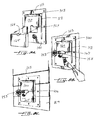
- FIG. 9A is an exploded view of a mounting assembly according to this invention with the mounting block in separable pieces.
- FIG. 9B is a perspective view of a mounting assembly according to this invention with a separable mounting block according to FIG. 9A and having an upper portion of the mounting block in place around a hose bib protruding from a wall of a building.
- FIG. 9C is a perspective view of the mounting assembly of FIG. 9A in place around a hose bib.
- FIG. 10A is a perspective view of the mounting bracket according to this invention with a trim extension thereon.
- FIG. 10B is a perspective view of the mounting bracket according to this invention with a mounting block installed over a trim extension on the bracket.
- FIG. 11A is a perspective view of the mounting bracket of this invention having a lip extending from an opening in the mounting bracket.
- FIG. 11B is a perspective view of the mounting bracket of this invention having a mounting block in place with the mounting bracket of FIG. 11A and engaging the lip.
- FIG. 11C is a cross section of the mounting assembly of FIG. 11B .
- the invention is a fixture mounting assembly ( 130 ) for attaching to the outside wall of a building (shown separately in FIGS. 1 and 2 as 100 , 120 and shown collectively in FIG. 3 as 130 ).
- the fixture mounting assembly ( 130 ) provides a convenient, aesthetically pleasing mechanism for installing fixtures (e.g., lights, electrical sockets, spigots, hose bibs and vents) to the side of a building that is to be covered with protective siding.
- fixtures e.g., lights, electrical sockets, spigots, hose bibs and vents
- the fixture mounting assembly ( 130 ) provides a continuous and consistent appearance when used with fiber cement siding (i.e., HardiPlankTM).
- the invention also provides additional protective features to ensure that the utility work on the outside of the house is protected from the elements.
- the fixture mounting assembly ( 130 ) includes an integral flashing component ( 103 ) around at least a portion of the fixture mounting assembly ( 130 ).
- the overall fixture mounting assembly ( 130 ) includes two separable parts—a wall mounting bracket ( 100 ) and mounting block ( 120 ).
- the wall mounting bracket ( 100 ) includes, at a minimum, a front face ( 101 ) that defines a mounting bracket opening ( 109 ) within an inner edge ( 102 ).
- the front face ( 101 ) may be generally recessed within the overall bracket ( 100 ) such that the front face ( 101 ) is surrounded by a substantially perpendicular inner wall (not shown).
- the front face ( 101 ) is also surrounded, at least in part, by a flange ( 107 ) integral with the mounting bracket body ( 100 ).
- the flange ( 107 ) includes openings ( 106 ) for nailing, screwing, or otherwise attaching the mounting bracket ( 100 ) to the outside wall of the building.
- the mounting bracket ( 100 ) includes an integral flashing component ( 103 ) that provides a useful path for rain or other drainage over the associated mounting block ( 120 ) when the fixture mounting assembly is fully intact (see Ref 130 ).
- the flashing component ( 103 ) extends outwardly at an angle from the mounting bracket ( 100 ) and over the mounting bracket opening ( 109 ). In a preferred embodiment the flashing component ( 103 ) extends from just below the uppermost inner edge of the flange ( 107 ).
- the flashing component ( 103 ) may also include a gusset ( 105 ) for support and a bottom ( 104 ) extending substantially parallel to the front face ( 101 ) of the mounting bracket ( 100 ).
- the angled top portion ( 103 A) of the flashing component ( 103 ) connects to the gusset ( 105 ) and the bottom ( 104 ) of the flashing component.
- the gusset ( 105 ) and the bottom ( 104 ) of the flashing component together define a peripheral edge ( 113 ) of the flashing component.
- the flashing component ( 103 ) therefore, defines a cavity ( 103 B) under an overall drip cap that extends over the mounting bracket opening ( 109 ) in the front face ( 101 ).
- the mounting bracket ( 100 ) may be formed by any number of techniques known in the art today.
- the mounting bracket ( 100 ), including the front face ( 101 ), the flange ( 107 ) and the flashing component ( 103 ) are all formed in a single piece construction.
- Such single piece construction may be accomplished by injection molding a plastic or any polymeric material used in the art today.
- the overall fixture mounting assembly ( 130 ) incorporates a detachable mounting block ( 120 ).
- the mounting block ( 120 ) is preferably formed of the same material as the siding used on the outside of the building.
- the mounting block ( 120 ) is a substantially rectangular section of fiber cement with a hollow opening defined therein by an inner wall ( 121 ).
- the hollow opening ( 129 ) in the mounting block ( 120 ) is useful to allow access through the mounting block and the front face opening ( 109 ) of the mounting bracket ( 100 ) (i.e., the mounting bracket opening ( 109 )).
- the outer wall of the building then includes a corresponding opening for utility access.
- the mounting block ( 120 ) fits over the mounting bracket ( 100 ) and into the cavity defined by the flashing component ( 103 ).
- the fixture ( 150 ) protruding from the wall ( 155 ) of the building extends through the mounting bracket opening ( 109 ) and fits against the second opening ( 129 ) defined by the mounting block ( 120 ).
- the fixture ( 150 ) engages the second opening ( 129 ), also referred to above as hollow opening ( 129 ) for a secure, substantially snug fit within the mounting block ( 120 ).
- the top edge ( 124 ) of the mounting block ( 120 ) slides into the flashing component ( 103 ) between the gusset ( 105 ) and the bottom ( 104 ) connected to the flashing component ( 103 ).
- a securing mechanism such as a nail, staple, or screw is optionally driven through the back side of the mounting bracket ( 100 ) into the mounting block ( 120 ) to ensure a secure engagement between the two when the assembly is used as shown in FIG. 3 .
- the invention includes an embodiment by which the fixture ( 150 , 151 ) protruding from the wall ( 155 ) of a building engages the mounting block ( 120 ) for protection.
- the mounting block is constructed of a uniform thickness (e.g., 1 inch) and may be formed of substantially the same material as the protective siding to be applied to the building.
- the mounting block is significantly thicker than the siding, meaning that upon installation, the mounting block juts outwardly from the protective siding on the building.
- the mounting block provides additional protection that is enhanced by its uniform thickness.
- the term “thickness” as used herein includes its usual meaning as a measurement (i.e., the distance from a rear face of the mounting block next to the mounting bracket to an opposite outward face of the mounting block that is exposed upon installation).
- the fixture at issue can be installed through the wall ( 155 ) of the building and the front face opening ( 109 ) in the mounting bracket.
- the fixture ( 150 , 151 ) is mounted to the building via the mounting bracket opening ( 109 ) and the hollow opening, or second opening ( 129 ), in the mounting block ( 120 ).
- the overall mounting assembly ( 130 ) with the fixture ( 150 , 151 ) therein can be attached to the outer wall ( 155 ) of the building via the flange ( 107 ) (i.e., the flange is nailed to the building as in FIG. 6 ).
- the completed mounting assembly ( 130 ) includes the integral flashing component ( 103 ) that provides a protective cover for the mounting block ( 120 ) and a continuous aesthetic appearance in which the mounting block ( 120 ) and the siding on the building match.
- the mounting bracket ( 100 ) includes the front face opening ( 109 ) in a standard size that is useful for multiple fixtures.
- the mounting block ( 120 ) may have a hollow opening (second opening ( 121 )) that is sized according to the fixture at hand.
- the hollow opening within the mounting block may be of any desirable shape or size that the consumer needs or that the project requires. For example, FIGS. 7 and 8 show the use of a round opening in the mounting assembly.
- the mounting bracket ( 100 ) may be manufactured with a front face ( 101 ) that is substantially solid—in other words, without the front face opening ( 109 ).
- the mounting bracket includes perforations ( 117 ), or scoring, to show different shapes of mounting bracket openings ( 109 ) that may be cut out.
- the scoring ( 117 ) may be in the form of intermittent cuts in the mounting bracket ( 100 ) body. The user then completes the cut to form a mounting bracket opening ( 109 ) that tracks one of the available scored designs ( 117 A- 117 D) on the back of the mounting bracket ( 100 .
- This embodiment allows more than one type of mounting bracket ( 100 ) to be formed from the same overall piece, depending upon the application at hand.
- FIG. 8 shows these perforations ( 117 ) on the back of the mounting bracket ( 100 ).
- FIG. 1 also shows an embodiment of the fixture mounting assembly according to this invention and includes side rails ( 111 , 112 ) for additional weather protection between the protective siding on the building and the mounting assembly.
- the side rails ( 111 , 112 ) run vertically from the gusset ( 105 ) supporting the flashing component ( 103 ) toward the bottom of the wall mounting bracket ( 100 ).
- the pieces may be formed integrally for a one piece construction.
- the overall fixture mounting assembly of FIG. 3 and FIGS. 5-7 includes two separable parts—a wall mounting bracket ( 100 ) and mounting block ( 120 ).
- the wall mounting bracket ( 100 ) includes, at a minimum, a front face ( 101 ) that defines a mounting bracket opening ( 109 ) within an inner edge ( 102 ).
- the front face ( 101 ) is generally separated into portions on one side of the overall bracket ( 101 ) such that the front face includes a flange or flange-like area ( 107 ) on one side of the sealing inner edge ( 102 ) and the mounting bracket opening ( 109 ) on the other side of the sealing inner edge ( 102 ).
- the mounting bracket has a pair of side rails ( 111 , 112 ) on either side of the flashing component ( 103 ). These side rails ( 111 , 112 ) are barriers on either side of the mounting bracket opening ( 109 ).
- the front face is also surrounded, at least in part, by a flange ( 107 ) integral with the mounting bracket body.
- the flange ( 107 ) includes openings ( 106 ) for nailing, screwing, or otherwise attaching the mounting bracket to the outside wall of the building.
- the mounting bracket ( 100 ) includes an integral flashing component ( 103 ) that provides a useful path for rain or other drainage over the associated mounting block ( 120 ) when the fixture mounting assembly ( 100 ) is fully intact.
- the flashing component ( 103 ) extends outwardly at an angle from the mounting bracket. In a preferred embodiment the flashing component ( 103 ) extends from just below the uppermost inner portion of the flange ( 107 ) and covers an upper area of the front face ( 101 ).
- the flashing component ( 103 ) may also include a gusset ( 105 ) for support and a bottom ( 104 ) extending substantially parallel to the front face ( 101 ) of the mounting bracket ( 100 ).
- the mounting block ( 120 ) fits between the side rails ( 111 , 112 ) and within the flashing component ( 103 ).
- the mounting block ( 120 ) is attached to the mounting bracket ( 100 ) by a staple or other attachment mechanism.
- the mounting block ( 120 ) is attached to the mounting bracket ( 100 ) by a staple from the back side of the face of the mounting bracket.
- the overall invention shown in FIGS. 1-8 sets the background for additional features included in the mounting bracket assembly ( 130 ).
- the same mounting bracket ( 100 ) can be used in a system by which the mounting block ( 120 ) is separated into two portions ( 160 , 165 ).
- the portions include arcuate indentions ( 167 , 168 ) that together form the second opening, i.e., the mounting block opening, through which a fixture ( 153 ) fits.
- This embodiment is particularly useful in installing the mounting assembly around a hose bib or a drip pipe, where the goal is to allow the inner edge of the mounting block to engage the fixture snugly for protection.
- the fixture is more conveniently installed through the second opening in the mounting assembly.
- the manufacturer may choose to ship the mounting assembly in the following manner.
- the upper portion ( 160 ) of the mounting block is attached to the mounting bracket ( 100 ) and engages the flashing component (e.g., the drip cap) ( 103 ) via the cavity ( 103 B) formed by the top ( 103 A), bottom ( 104 ), and gusset ( 105 ) of the flashing component ( 103 ).
- the bottom portion ( 165 ) of the mounting block ( 120 ) is temporarily attached to the mounting bracket ( 100 ) by glue or some other removable adhesive.
- the installer removes the bottom component ( 165 ) and scrapes off the glue pad as shown in FIG. 9B .
- the mounting bracket ( 100 ) with the top portion ( 160 ) of the mounting block installed therein is placed over the fixture ( 153 ), such as a spigot shown in FIG. 9B and FIG. 9C .
- the installer then attaches the mounting block bottom portion ( 165 ) around the spigot and attaches the bottom portion ( 165 ) to the mounting bracket ( 100 ) by known means (e.g., nails or tacks).
- the mounting block ( 160 , 165 ) defines a precisely dimensioned second opening in the mounting assembly that engages the fixture ( 153 ) extending there through. Such a complete fit around the fixture enhances the protection that the mounting assembly offers to the elements or unexpected leaks.
- the protective siding is installed adjacent the mounting block. In one embodiment, the protective siding is installed in direct contact with the side rails on the mounting bracket.
- FIGS. 10A and 10B show yet another feature that is optionally included in the mounting assembly of this invention.
- FIG. 10A shows the mounting bracket ( 100 ) just as described above, but with the addition of a trim extension ( 177 ) at the bottom of the bracket ( 100 ).
- the trim extension is useful as a replacement for standard trim coil used as flashing around the fixture installation.
- a bracket around the fixture of a building is positioned over a lining, or a layer of trim coil, that protects the area under the fixture.
- the trim coil is a sheet of aluminum over the wall of the building and under the bracket supporting the fixture.
- the trim extension ( 170 ) is meant to be hidden by the protective siding on the building, and protective siding comes in a variety of dimensions. Accordingly, the trim extension ( 170 ) shown in FIGS. 10A and 10B is scored to allow the installer to size the trim extension ( 170 ) according to the use at hand. The installer simply completes the scored cuts ( 171 ) shown in the figures, breaks off the excess trim extension ( 170 ), and uses the mounting bracket ( 100 ) with a trim extension ( 170 ) in place of a mounting bracket plus a layer of trim coil.
- a lip or ridge ( 180 ) that may extend from the mounting bracket ( 100 ) from the inner edge ( 102 ) defining the mounting bracket opening.
- the lip ( 180 ) is designed to engage the inner surface of the second opening ( 129 ) of the mounting assembly ( 130 ), i.e., the opening in the mounting block ( 120 ). Again, this lip engagement provides even more sealing qualities and protection from the elements for the fixture engaging the mounting block.
- the lip of the mounting bracket is illustrated in FIGS. 11A-11C .
Landscapes
- Engineering & Computer Science (AREA)
- Civil Engineering (AREA)
- Structural Engineering (AREA)
- General Engineering & Computer Science (AREA)
- Finishing Walls (AREA)
Abstract
Description
Claims (21)
Priority Applications (1)
| Application Number | Priority Date | Filing Date | Title |
|---|---|---|---|
| US13/119,910 US8881468B2 (en) | 2008-09-19 | 2009-09-18 | Fixture wall mount assembly with integral flashing |
Applications Claiming Priority (4)
| Application Number | Priority Date | Filing Date | Title |
|---|---|---|---|
| US9848508P | 2008-09-19 | 2008-09-19 | |
| US11671208P | 2008-11-21 | 2008-11-21 | |
| US13/119,910 US8881468B2 (en) | 2008-09-19 | 2009-09-18 | Fixture wall mount assembly with integral flashing |
| PCT/US2009/057455 WO2010033787A1 (en) | 2008-09-19 | 2009-09-18 | Fixture wall mount assembly with integral flashing |
Publications (2)
| Publication Number | Publication Date |
|---|---|
| US20110240813A1 US20110240813A1 (en) | 2011-10-06 |
| US8881468B2 true US8881468B2 (en) | 2014-11-11 |
Family
ID=41426172
Family Applications (1)
| Application Number | Title | Priority Date | Filing Date |
|---|---|---|---|
| US13/119,910 Active 2030-11-03 US8881468B2 (en) | 2008-09-19 | 2009-09-18 | Fixture wall mount assembly with integral flashing |
Country Status (6)
| Country | Link |
|---|---|
| US (1) | US8881468B2 (en) |
| EP (1) | EP2324283A1 (en) |
| AU (1) | AU2009293109A1 (en) |
| CA (1) | CA2737808C (en) |
| RU (1) | RU2011115193A (en) |
| WO (1) | WO2010033787A1 (en) |
Cited By (18)
| Publication number | Priority date | Publication date | Assignee | Title |
|---|---|---|---|---|
| US20150345808A1 (en) * | 2014-05-28 | 2015-12-03 | Janiece R. HNILICA-MAXWELL | Decorative Dryer Vent |
| US20160268747A1 (en) * | 2015-03-11 | 2016-09-15 | Liang Light Chen | Power distributor mounting device |
| US9651174B2 (en) * | 2015-07-27 | 2017-05-16 | Gabriel V. Lechuga | Wall mounted receiver |
| US10014674B1 (en) * | 2017-07-05 | 2018-07-03 | Seeless Solutions, Inc. | Recessed wall mounting apparatus and method |
| US20180291597A1 (en) * | 2017-04-07 | 2018-10-11 | David Hunt | Mounting devices and methods for exterior faucets and lines |
| US20180312331A1 (en) * | 2017-04-26 | 2018-11-01 | Christopher Wayne Forrest | Shipping Container Adapter |
| USD860025S1 (en) * | 2018-07-13 | 2019-09-17 | Shalom Illouz | Smoke detector mount |
| USD860024S1 (en) * | 2018-07-12 | 2019-09-17 | Shalom Illouz | Smoke detector mount |
| US10487512B2 (en) * | 2017-05-15 | 2019-11-26 | Snowventco Limited | Roof vent with integrated shield |
| USD878905S1 (en) * | 2019-06-13 | 2020-03-24 | Shalom Illouz | Mount for electronic personal assistant |
| USD879501S1 (en) * | 2018-07-17 | 2020-03-31 | Shalom Illouz | Wall mount |
| USD880189S1 (en) * | 2017-07-05 | 2020-04-07 | Shalom Illouz | Wall mount |
| USD897130S1 (en) * | 2017-07-05 | 2020-09-29 | Shalom Illouz | Wall mount |
| USD897188S1 (en) * | 2018-07-17 | 2020-09-29 | Shalom Illouz | Wireless access point mount |
| US20210140152A1 (en) * | 2020-01-22 | 2021-05-13 | Paul Arlo Blumer | Fixture accessory apparatus and method of using same |
| USD950994S1 (en) * | 2017-06-14 | 2022-05-10 | Legrand A V Inc. | Panel portion for an electronics rack |
| US20220381030A1 (en) * | 2021-05-25 | 2022-12-01 | John Clinton Carter | Fixture-ready block |
| USD1074941S1 (en) | 2022-12-06 | 2025-05-13 | Blumare, L.L.C. | Plumbing fixture accessory plate |
Families Citing this family (2)
| Publication number | Priority date | Publication date | Assignee | Title |
|---|---|---|---|---|
| US12163336B2 (en) * | 2021-12-09 | 2024-12-10 | Pontiac Trail Products, LLC | Mounting block for vinyl siding |
| USD1061217S1 (en) * | 2023-01-19 | 2025-02-11 | Ben Korez | Wall mounting device |
Citations (40)
| Publication number | Priority date | Publication date | Assignee | Title |
|---|---|---|---|---|
| US2167419A (en) | 1938-01-05 | 1939-07-25 | Heanes Herbert | Electric meter box |
| US3180595A (en) | 1962-03-29 | 1965-04-27 | Ra Ma Company Inc | Wall fixture mounting |
| US4156272A (en) | 1977-08-10 | 1979-05-22 | Mcgraw-Edison Company | Mounting bracket for light fixture |
| US4265365A (en) | 1978-04-28 | 1981-05-05 | Slater Electric Inc. | Moisture resistant electrical outlet box |
| US4336673A (en) | 1980-09-05 | 1982-06-29 | Monitronik Ltee. | Mosaic display panel |
| US4635168A (en) | 1985-06-17 | 1987-01-06 | Crowley Charles H | Light fixture mounting pedestal and method of installing same |
| US4726152A (en) | 1986-11-24 | 1988-02-23 | Vagedes Industries, Inc. | Bracket for mounting a fixture on a wall |
| US4854093A (en) | 1988-09-02 | 1989-08-08 | Kellom Gary J | Fixture mount |
| US4887195A (en) | 1988-08-01 | 1989-12-12 | Donelan John M | Illuminated house number enclosure |
| US4920708A (en) | 1988-05-10 | 1990-05-01 | Tapco Products Company, Inc. | Wall mounting assembly |
| US5000409A (en) | 1989-12-04 | 1991-03-19 | Tapco Products Company, Inc. | One piece wall mounting bracket |
| US5133165A (en) | 1991-03-22 | 1992-07-28 | Taurus Safety Products, Inc. | Outlet cover u-trim |
| US5221069A (en) | 1992-05-12 | 1993-06-22 | Dana Innovations | Telescoping support bracket |
| US5275366A (en) | 1992-11-18 | 1994-01-04 | Aluminum Company Of America | Fixture mounting bracket and associated fixture assembly |
| US5303522A (en) | 1993-05-21 | 1994-04-19 | Michael Vagedes | Internally flashed siding channel |
| US5326060A (en) | 1992-06-25 | 1994-07-05 | Mid-America Building Products Corporation | Plastic building wall mount assembly |
| US5526619A (en) | 1994-12-01 | 1996-06-18 | Richwood Building Products, Inc. | Trim assembly for finishing a fixture on a building exterior |
| US5549266A (en) | 1994-04-22 | 1996-08-27 | Kentech Plastics, Inc. | Mounting bracket with water deflector |
| US5578791A (en) | 1994-05-12 | 1996-11-26 | Bosse, Jr.; John J. | Combined wall mount and electrical outlet box |
| US5722208A (en) | 1994-08-16 | 1998-03-03 | Thermo Plastic Works, Inc. | Wall mounting system for electrical devices |
| US5775032A (en) | 1997-05-19 | 1998-07-07 | Vantage Products Corporation | Exterior mounting plate assembly |
| US5918431A (en) | 1996-09-19 | 1999-07-06 | Tapco International | Split-block recess mount apparatus |
| US5947816A (en) | 1995-06-06 | 1999-09-07 | Tapco International Corporation | Modular soffit vent |
| US6355882B1 (en) | 1999-08-13 | 2002-03-12 | Arlington Industries, Inc. | Flush-mount electrical junction box |
| US6378910B1 (en) | 1999-09-30 | 2002-04-30 | Steven Maiman | Plumber's flange and method for using the same |
| US6417447B1 (en) | 1994-05-12 | 2002-07-09 | Boss Products Corporation | Combined wall mount and electrical outlet box |
| US20030136060A1 (en) * | 2002-01-02 | 2003-07-24 | Bonshor David J. | Water deflecting apparatus |
| US6825414B2 (en) | 2002-09-24 | 2004-11-30 | Bluegrass Products, L.L.C. | Exterior mounting block for electrical fixtures |
| US20060117682A1 (en) | 2004-11-25 | 2006-06-08 | Hsi-Fan Chang | Composite outlet |
| US7408111B2 (en) | 2005-12-22 | 2008-08-05 | Tapco International Corporation | Wall mount assembly |
| US7516578B2 (en) | 2005-05-20 | 2009-04-14 | Tapco International Corporation | Exterior siding mounting brackets with a water diversion device |
| US7516576B1 (en) * | 2000-10-19 | 2009-04-14 | Berger Building Products, Inc. | Snow stop |
| US7549258B2 (en) | 2003-09-02 | 2009-06-23 | Tapco International Corporation | Adjustable housing assembly |
| US7610726B2 (en) | 2005-05-05 | 2009-11-03 | Tapco International Corporation | Housing assembly |
| US20090320384A1 (en) | 2009-08-28 | 2009-12-31 | Vpl Enterprises | Water deviation unit for external wall fixtures |
| US7676993B2 (en) * | 2005-06-13 | 2010-03-16 | Tapco International Corporation | Exterior siding mounting bracket assembly and method of assembly |
| US7752814B2 (en) | 2005-03-28 | 2010-07-13 | Tapco International Corporation | Water deflection apparatus for use with a wall mounting bracket |
| US7762039B2 (en) | 2008-04-04 | 2010-07-27 | Hickey Thomas B | Electrical fixture apparatus and installation method |
| US7770854B2 (en) * | 2005-08-31 | 2010-08-10 | Tapco International Corporation | Adjustable mounting bracket assembly for exterior siding |
| US7880085B2 (en) * | 2005-12-22 | 2011-02-01 | Tapco International Corporation | Wall mount assembly |
-
2009
- 2009-09-18 EP EP09792705A patent/EP2324283A1/en not_active Withdrawn
- 2009-09-18 WO PCT/US2009/057455 patent/WO2010033787A1/en not_active Ceased
- 2009-09-18 CA CA2737808A patent/CA2737808C/en active Active
- 2009-09-18 US US13/119,910 patent/US8881468B2/en active Active
- 2009-09-18 RU RU2011115193/07A patent/RU2011115193A/en not_active Application Discontinuation
- 2009-09-18 AU AU2009293109A patent/AU2009293109A1/en not_active Abandoned
Patent Citations (44)
| Publication number | Priority date | Publication date | Assignee | Title |
|---|---|---|---|---|
| US2167419A (en) | 1938-01-05 | 1939-07-25 | Heanes Herbert | Electric meter box |
| US3180595A (en) | 1962-03-29 | 1965-04-27 | Ra Ma Company Inc | Wall fixture mounting |
| US4156272A (en) | 1977-08-10 | 1979-05-22 | Mcgraw-Edison Company | Mounting bracket for light fixture |
| US4265365A (en) | 1978-04-28 | 1981-05-05 | Slater Electric Inc. | Moisture resistant electrical outlet box |
| US4336673A (en) | 1980-09-05 | 1982-06-29 | Monitronik Ltee. | Mosaic display panel |
| US4635168A (en) | 1985-06-17 | 1987-01-06 | Crowley Charles H | Light fixture mounting pedestal and method of installing same |
| US4726152A (en) | 1986-11-24 | 1988-02-23 | Vagedes Industries, Inc. | Bracket for mounting a fixture on a wall |
| US4920708A (en) | 1988-05-10 | 1990-05-01 | Tapco Products Company, Inc. | Wall mounting assembly |
| US4887195A (en) | 1988-08-01 | 1989-12-12 | Donelan John M | Illuminated house number enclosure |
| US4854093A (en) | 1988-09-02 | 1989-08-08 | Kellom Gary J | Fixture mount |
| US5000409A (en) | 1989-12-04 | 1991-03-19 | Tapco Products Company, Inc. | One piece wall mounting bracket |
| US5133165A (en) | 1991-03-22 | 1992-07-28 | Taurus Safety Products, Inc. | Outlet cover u-trim |
| US5221069A (en) | 1992-05-12 | 1993-06-22 | Dana Innovations | Telescoping support bracket |
| US5326060A (en) | 1992-06-25 | 1994-07-05 | Mid-America Building Products Corporation | Plastic building wall mount assembly |
| USRE38881E1 (en) | 1992-06-25 | 2005-11-22 | Tapco International Corporation | Plastic building wall mount assembly |
| US5275366A (en) | 1992-11-18 | 1994-01-04 | Aluminum Company Of America | Fixture mounting bracket and associated fixture assembly |
| US5303522A (en) | 1993-05-21 | 1994-04-19 | Michael Vagedes | Internally flashed siding channel |
| US5549266A (en) | 1994-04-22 | 1996-08-27 | Kentech Plastics, Inc. | Mounting bracket with water deflector |
| US5578791A (en) | 1994-05-12 | 1996-11-26 | Bosse, Jr.; John J. | Combined wall mount and electrical outlet box |
| US6417447B1 (en) | 1994-05-12 | 2002-07-09 | Boss Products Corporation | Combined wall mount and electrical outlet box |
| US5722208A (en) | 1994-08-16 | 1998-03-03 | Thermo Plastic Works, Inc. | Wall mounting system for electrical devices |
| US5526619A (en) | 1994-12-01 | 1996-06-18 | Richwood Building Products, Inc. | Trim assembly for finishing a fixture on a building exterior |
| US5947816A (en) | 1995-06-06 | 1999-09-07 | Tapco International Corporation | Modular soffit vent |
| US5918431A (en) | 1996-09-19 | 1999-07-06 | Tapco International | Split-block recess mount apparatus |
| US5775032A (en) | 1997-05-19 | 1998-07-07 | Vantage Products Corporation | Exterior mounting plate assembly |
| US6355882B1 (en) | 1999-08-13 | 2002-03-12 | Arlington Industries, Inc. | Flush-mount electrical junction box |
| US6378910B1 (en) | 1999-09-30 | 2002-04-30 | Steven Maiman | Plumber's flange and method for using the same |
| US7516576B1 (en) * | 2000-10-19 | 2009-04-14 | Berger Building Products, Inc. | Snow stop |
| US6951081B2 (en) * | 2002-01-02 | 2005-10-04 | Bonshor David J | Water deflecting apparatus |
| US20030136060A1 (en) * | 2002-01-02 | 2003-07-24 | Bonshor David J. | Water deflecting apparatus |
| US6825414B2 (en) | 2002-09-24 | 2004-11-30 | Bluegrass Products, L.L.C. | Exterior mounting block for electrical fixtures |
| US7549258B2 (en) | 2003-09-02 | 2009-06-23 | Tapco International Corporation | Adjustable housing assembly |
| US20060117682A1 (en) | 2004-11-25 | 2006-06-08 | Hsi-Fan Chang | Composite outlet |
| US7752814B2 (en) | 2005-03-28 | 2010-07-13 | Tapco International Corporation | Water deflection apparatus for use with a wall mounting bracket |
| US7610726B2 (en) | 2005-05-05 | 2009-11-03 | Tapco International Corporation | Housing assembly |
| US7516578B2 (en) | 2005-05-20 | 2009-04-14 | Tapco International Corporation | Exterior siding mounting brackets with a water diversion device |
| US7748174B2 (en) * | 2005-05-20 | 2010-07-06 | Tapco International Corporation | Exterior siding mounting brackets with a water diversion device |
| US7676993B2 (en) * | 2005-06-13 | 2010-03-16 | Tapco International Corporation | Exterior siding mounting bracket assembly and method of assembly |
| US7770854B2 (en) * | 2005-08-31 | 2010-08-10 | Tapco International Corporation | Adjustable mounting bracket assembly for exterior siding |
| US7408111B2 (en) | 2005-12-22 | 2008-08-05 | Tapco International Corporation | Wall mount assembly |
| US7880085B2 (en) * | 2005-12-22 | 2011-02-01 | Tapco International Corporation | Wall mount assembly |
| US20110131891A1 (en) * | 2005-12-22 | 2011-06-09 | Tapco International Corporation | Wall mount assembly |
| US7762039B2 (en) | 2008-04-04 | 2010-07-27 | Hickey Thomas B | Electrical fixture apparatus and installation method |
| US20090320384A1 (en) | 2009-08-28 | 2009-12-31 | Vpl Enterprises | Water deviation unit for external wall fixtures |
Non-Patent Citations (2)
| Title |
|---|
| Website: http://www.duraflo.com/Duraflo.aspx?categoryID=89, accessed on Jul. 14, 2011. |
| Website: http://www.primex.ca/large-products/construction/HVAC-outdoor/dv.htm, accessed on Jul. 14, 2011. |
Cited By (31)
| Publication number | Priority date | Publication date | Assignee | Title |
|---|---|---|---|---|
| US10422134B2 (en) * | 2010-02-19 | 2019-09-24 | Gabriel V. Lechuga | Wall mounted receiver |
| US20150345808A1 (en) * | 2014-05-28 | 2015-12-03 | Janiece R. HNILICA-MAXWELL | Decorative Dryer Vent |
| US20160268747A1 (en) * | 2015-03-11 | 2016-09-15 | Liang Light Chen | Power distributor mounting device |
| US9543720B2 (en) * | 2015-03-11 | 2017-01-10 | Liang Light Chen | Power distributor mounting device |
| US9651174B2 (en) * | 2015-07-27 | 2017-05-16 | Gabriel V. Lechuga | Wall mounted receiver |
| US20180298610A1 (en) * | 2016-07-27 | 2018-10-18 | Gabriel V. Lechuga | Wall Mounted Receiver |
| US10151112B2 (en) * | 2016-07-27 | 2018-12-11 | Gabriel V. Lechuga | Wall mounted receiver |
| US10557253B2 (en) * | 2017-04-07 | 2020-02-11 | David Hunt | Mounting devices and methods for exterior faucets and lines |
| US20180291597A1 (en) * | 2017-04-07 | 2018-10-11 | David Hunt | Mounting devices and methods for exterior faucets and lines |
| US20180312331A1 (en) * | 2017-04-26 | 2018-11-01 | Christopher Wayne Forrest | Shipping Container Adapter |
| US10723547B2 (en) * | 2017-04-26 | 2020-07-28 | Christopher Wayne Forrest | Shipping container adapter |
| USRE50321E1 (en) * | 2017-04-26 | 2025-03-04 | Container Creations LLC | Shipping container adapter |
| US10487512B2 (en) * | 2017-05-15 | 2019-11-26 | Snowventco Limited | Roof vent with integrated shield |
| USD950994S1 (en) * | 2017-06-14 | 2022-05-10 | Legrand A V Inc. | Panel portion for an electronics rack |
| USD897130S1 (en) * | 2017-07-05 | 2020-09-29 | Shalom Illouz | Wall mount |
| CN110832723B (en) * | 2017-07-05 | 2021-10-29 | 西莱斯解决方案公司 | Recessed Wall Mount Equipment |
| WO2019010334A1 (en) * | 2017-07-05 | 2019-01-10 | Seeless Solutions, Inc. | Recessed wall mounting apparatus and method |
| CN110832723A (en) * | 2017-07-05 | 2020-02-21 | 西莱斯解决方案公司 | Recessed wall mounting apparatus and method |
| USD880189S1 (en) * | 2017-07-05 | 2020-04-07 | Shalom Illouz | Wall mount |
| US10014674B1 (en) * | 2017-07-05 | 2018-07-03 | Seeless Solutions, Inc. | Recessed wall mounting apparatus and method |
| USD860024S1 (en) * | 2018-07-12 | 2019-09-17 | Shalom Illouz | Smoke detector mount |
| USD860025S1 (en) * | 2018-07-13 | 2019-09-17 | Shalom Illouz | Smoke detector mount |
| USD897188S1 (en) * | 2018-07-17 | 2020-09-29 | Shalom Illouz | Wireless access point mount |
| USD879501S1 (en) * | 2018-07-17 | 2020-03-31 | Shalom Illouz | Wall mount |
| USD878905S1 (en) * | 2019-06-13 | 2020-03-24 | Shalom Illouz | Mount for electronic personal assistant |
| US20210140152A1 (en) * | 2020-01-22 | 2021-05-13 | Paul Arlo Blumer | Fixture accessory apparatus and method of using same |
| US11795668B2 (en) * | 2020-01-22 | 2023-10-24 | Blumare, L.L.C. | Fixture accessory apparatus and method of using same |
| USD1034920S1 (en) | 2020-01-22 | 2024-07-09 | Blumare, L.L.C. | Plumbing fixture accessory plate |
| US20220381030A1 (en) * | 2021-05-25 | 2022-12-01 | John Clinton Carter | Fixture-ready block |
| US11834829B2 (en) * | 2021-05-25 | 2023-12-05 | John Clinton Carter | Fixture-ready block |
| USD1074941S1 (en) | 2022-12-06 | 2025-05-13 | Blumare, L.L.C. | Plumbing fixture accessory plate |
Also Published As
| Publication number | Publication date |
|---|---|
| EP2324283A1 (en) | 2011-05-25 |
| CA2737808A1 (en) | 2010-03-25 |
| CA2737808C (en) | 2015-04-28 |
| RU2011115193A (en) | 2012-10-27 |
| WO2010033787A1 (en) | 2010-03-25 |
| AU2009293109A1 (en) | 2010-03-25 |
| US20110240813A1 (en) | 2011-10-06 |
Similar Documents
| Publication | Publication Date | Title |
|---|---|---|
| US8881468B2 (en) | Fixture wall mount assembly with integral flashing | |
| US7902459B2 (en) | Junction box cover assembly | |
| US6957896B2 (en) | Aperture edging member and method | |
| US8950134B2 (en) | Trim molding system attached to a wall surface having existing moldings thereon | |
| US6643990B2 (en) | Modular molding system | |
| US5000409A (en) | One piece wall mounting bracket | |
| US20130042539A1 (en) | Apparatus and method for mounting covers and devices co-planar with walls and other building surfaces | |
| US6429371B2 (en) | Electrical block | |
| US6774304B1 (en) | Siding box assembly | |
| CA2105825C (en) | Internally flashed siding channel | |
| US6723921B2 (en) | Exterior mounting block for electrical fixtures | |
| RU2323316C2 (en) | Kit including mounting members to opening perimeter edge finishing, mounting structure for opening perimeter edge finishing and mounting member assemblage method | |
| US8779290B1 (en) | Corner wall conduit | |
| US20060213132A1 (en) | Water deflection apparatus for use with a wall mounting bracket | |
| CA2839666C (en) | Profile system | |
| US7408111B2 (en) | Wall mount assembly | |
| CA2544601C (en) | Modesty panel and external wall execution structure using said modesty panel | |
| CA2841180A1 (en) | Fastening a ceiling trim | |
| US20100107548A1 (en) | Cover for siding trim member | |
| KR20230122982A (en) | easy ceiling finishes materials | |
| CA2509722A1 (en) | Crown molding assembly and related kit | |
| US20090321433A1 (en) | Protective electrical box cover | |
| US20070193197A1 (en) | Trim structure and bracket | |
| EP1108098B1 (en) | Aperture edging member and method | |
| JP2001234617A (en) | Modified eaves edge structure |
Legal Events
| Date | Code | Title | Description |
|---|---|---|---|
| AS | Assignment |
Owner name: TAPCO INTERNATIONAL CORPORATION, MICHIGAN Free format text: ASSIGNMENT OF ASSIGNORS INTEREST;ASSIGNOR:MCMULLEN, BRIAN K.;REEL/FRAME:026016/0518 Effective date: 20101111 |
|
| STCF | Information on status: patent grant |
Free format text: PATENTED CASE |
|
| AS | Assignment |
Owner name: DEUTSCHE BANK AG NEW YORK BRANCH, AS ADMINISTRATIV Free format text: SECURITY AGREEMENT;ASSIGNORS:HEADWATERS INCORPORATED, AS GRANTOR;TAPCO INTERNATIONAL CORPORATION, A MICHIGAN CORPORATION;HEADWATERS HEAVY OIL, LLC, A UTAH CORPORATION;AND OTHERS;REEL/FRAME:035327/0462 Effective date: 20150324 Owner name: DEUTSCHE BANK AG NEW YORK BRANCH, AS ADMINISTRATIVE AGENT, NEW YORK Free format text: SECURITY AGREEMENT;ASSIGNORS:HEADWATERS INCORPORATED, AS GRANTOR;TAPCO INTERNATIONAL CORPORATION, A MICHIGAN CORPORATION;HEADWATERS HEAVY OIL, LLC, A UTAH CORPORATION;AND OTHERS;REEL/FRAME:035327/0462 Effective date: 20150324 |
|
| AS | Assignment |
Owner name: TAPCO INTERNATIONAL CORPORATION, UTAH Free format text: RELEASE BY SECURED PARTY;ASSIGNOR:DEUTSCHE BANK AG NEW YORK BRANCH;REEL/FRAME:042422/0640 Effective date: 20170508 Owner name: HEADWATERS RESOURCES, INC., UTAH Free format text: RELEASE BY SECURED PARTY;ASSIGNOR:DEUTSCHE BANK AG NEW YORK BRANCH;REEL/FRAME:042422/0640 Effective date: 20170508 Owner name: HEADWATERS INCORPORATED, UTAH Free format text: RELEASE BY SECURED PARTY;ASSIGNOR:DEUTSCHE BANK AG NEW YORK BRANCH;REEL/FRAME:042422/0640 Effective date: 20170508 Owner name: HEADWATERS HEAVY OIL, LLC, UTAH Free format text: RELEASE BY SECURED PARTY;ASSIGNOR:DEUTSCHE BANK AG NEW YORK BRANCH;REEL/FRAME:042422/0640 Effective date: 20170508 |
|
| MAFP | Maintenance fee payment |
Free format text: PAYMENT OF MAINTENANCE FEE, 4TH YEAR, LARGE ENTITY (ORIGINAL EVENT CODE: M1551) Year of fee payment: 4 |
|
| AS | Assignment |
Owner name: BORAL BUILDING PRODUCTS INC., MICHIGAN Free format text: CHANGE OF NAME;ASSIGNOR:TAPCO INTERNATIONAL CORPORATION;REEL/FRAME:050261/0206 Effective date: 20180701 |
|
| MAFP | Maintenance fee payment |
Free format text: PAYMENT OF MAINTENANCE FEE, 8TH YEAR, LARGE ENTITY (ORIGINAL EVENT CODE: M1552); ENTITY STATUS OF PATENT OWNER: LARGE ENTITY Year of fee payment: 8 |
|
| AS | Assignment |
Owner name: WESTLAKE ROYAL BUILDING PRODUCTS INC., DELAWARE Free format text: CHANGE OF NAME;ASSIGNOR:BORAL BUILDING PRODUCTS INC.;REEL/FRAME:063256/0243 Effective date: 20211029 |