US8880292B2 - Device for estimating vehicle body vibration and controller for suppressing vehicle body vibration using same - Google Patents
Device for estimating vehicle body vibration and controller for suppressing vehicle body vibration using same Download PDFInfo
- Publication number
- US8880292B2 US8880292B2 US13/812,088 US201113812088A US8880292B2 US 8880292 B2 US8880292 B2 US 8880292B2 US 201113812088 A US201113812088 A US 201113812088A US 8880292 B2 US8880292 B2 US 8880292B2
- Authority
- US
- United States
- Prior art keywords
- vehicle body
- body vibration
- vibration
- braking force
- wheel speed
- Prior art date
- Legal status (The legal status is an assumption and is not a legal conclusion. Google has not performed a legal analysis and makes no representation as to the accuracy of the status listed.)
- Active, expires
Links
Images


Classifications
-
- B—PERFORMING OPERATIONS; TRANSPORTING
- B60—VEHICLES IN GENERAL
- B60T—VEHICLE BRAKE CONTROL SYSTEMS OR PARTS THEREOF; BRAKE CONTROL SYSTEMS OR PARTS THEREOF, IN GENERAL; ARRANGEMENT OF BRAKING ELEMENTS ON VEHICLES IN GENERAL; PORTABLE DEVICES FOR PREVENTING UNWANTED MOVEMENT OF VEHICLES; VEHICLE MODIFICATIONS TO FACILITATE COOLING OF BRAKES
- B60T8/00—Arrangements for adjusting wheel-braking force to meet varying vehicular or ground-surface conditions, e.g. limiting or varying distribution of braking force
- B60T8/17—Using electrical or electronic regulation means to control braking
- B60T8/171—Detecting parameters used in the regulation; Measuring values used in the regulation
-
- B—PERFORMING OPERATIONS; TRANSPORTING
- B60—VEHICLES IN GENERAL
- B60L—PROPULSION OF ELECTRICALLY-PROPELLED VEHICLES; SUPPLYING ELECTRIC POWER FOR AUXILIARY EQUIPMENT OF ELECTRICALLY-PROPELLED VEHICLES; ELECTRODYNAMIC BRAKE SYSTEMS FOR VEHICLES IN GENERAL; MAGNETIC SUSPENSION OR LEVITATION FOR VEHICLES; MONITORING OPERATING VARIABLES OF ELECTRICALLY-PROPELLED VEHICLES; ELECTRIC SAFETY DEVICES FOR ELECTRICALLY-PROPELLED VEHICLES
- B60L3/00—Electric devices on electrically-propelled vehicles for safety purposes; Monitoring operating variables, e.g. speed, deceleration or energy consumption
- B60L3/10—Indicating wheel slip ; Correction of wheel slip
- B60L3/102—Indicating wheel slip ; Correction of wheel slip of individual wheels
-
- B—PERFORMING OPERATIONS; TRANSPORTING
- B60—VEHICLES IN GENERAL
- B60T—VEHICLE BRAKE CONTROL SYSTEMS OR PARTS THEREOF; BRAKE CONTROL SYSTEMS OR PARTS THEREOF, IN GENERAL; ARRANGEMENT OF BRAKING ELEMENTS ON VEHICLES IN GENERAL; PORTABLE DEVICES FOR PREVENTING UNWANTED MOVEMENT OF VEHICLES; VEHICLE MODIFICATIONS TO FACILITATE COOLING OF BRAKES
- B60T8/00—Arrangements for adjusting wheel-braking force to meet varying vehicular or ground-surface conditions, e.g. limiting or varying distribution of braking force
- B60T8/17—Using electrical or electronic regulation means to control braking
- B60T8/1755—Brake regulation specially adapted to control the stability of the vehicle, e.g. taking into account yaw rate or transverse acceleration in a curve
-
- B—PERFORMING OPERATIONS; TRANSPORTING
- B60—VEHICLES IN GENERAL
- B60W—CONJOINT CONTROL OF VEHICLE SUB-UNITS OF DIFFERENT TYPE OR DIFFERENT FUNCTION; CONTROL SYSTEMS SPECIALLY ADAPTED FOR HYBRID VEHICLES; ROAD VEHICLE DRIVE CONTROL SYSTEMS FOR PURPOSES NOT RELATED TO THE CONTROL OF A PARTICULAR SUB-UNIT
- B60W10/00—Conjoint control of vehicle sub-units of different type or different function
- B60W10/04—Conjoint control of vehicle sub-units of different type or different function including control of propulsion units
-
- B—PERFORMING OPERATIONS; TRANSPORTING
- B60—VEHICLES IN GENERAL
- B60W—CONJOINT CONTROL OF VEHICLE SUB-UNITS OF DIFFERENT TYPE OR DIFFERENT FUNCTION; CONTROL SYSTEMS SPECIALLY ADAPTED FOR HYBRID VEHICLES; ROAD VEHICLE DRIVE CONTROL SYSTEMS FOR PURPOSES NOT RELATED TO THE CONTROL OF A PARTICULAR SUB-UNIT
- B60W10/00—Conjoint control of vehicle sub-units of different type or different function
- B60W10/18—Conjoint control of vehicle sub-units of different type or different function including control of braking systems
- B60W10/184—Conjoint control of vehicle sub-units of different type or different function including control of braking systems with wheel brakes
-
- B—PERFORMING OPERATIONS; TRANSPORTING
- B60—VEHICLES IN GENERAL
- B60W—CONJOINT CONTROL OF VEHICLE SUB-UNITS OF DIFFERENT TYPE OR DIFFERENT FUNCTION; CONTROL SYSTEMS SPECIALLY ADAPTED FOR HYBRID VEHICLES; ROAD VEHICLE DRIVE CONTROL SYSTEMS FOR PURPOSES NOT RELATED TO THE CONTROL OF A PARTICULAR SUB-UNIT
- B60W30/00—Purposes of road vehicle drive control systems not related to the control of a particular sub-unit, e.g. of systems using conjoint control of vehicle sub-units
- B60W30/02—Control of vehicle driving stability
- B60W30/025—Control of vehicle driving stability related to comfort of drivers or passengers
-
- B—PERFORMING OPERATIONS; TRANSPORTING
- B60—VEHICLES IN GENERAL
- B60W—CONJOINT CONTROL OF VEHICLE SUB-UNITS OF DIFFERENT TYPE OR DIFFERENT FUNCTION; CONTROL SYSTEMS SPECIALLY ADAPTED FOR HYBRID VEHICLES; ROAD VEHICLE DRIVE CONTROL SYSTEMS FOR PURPOSES NOT RELATED TO THE CONTROL OF A PARTICULAR SUB-UNIT
- B60W30/00—Purposes of road vehicle drive control systems not related to the control of a particular sub-unit, e.g. of systems using conjoint control of vehicle sub-units
- B60W30/18—Propelling the vehicle
- B60W30/20—Reducing vibrations in the driveline
-
- B—PERFORMING OPERATIONS; TRANSPORTING
- B60—VEHICLES IN GENERAL
- B60W—CONJOINT CONTROL OF VEHICLE SUB-UNITS OF DIFFERENT TYPE OR DIFFERENT FUNCTION; CONTROL SYSTEMS SPECIALLY ADAPTED FOR HYBRID VEHICLES; ROAD VEHICLE DRIVE CONTROL SYSTEMS FOR PURPOSES NOT RELATED TO THE CONTROL OF A PARTICULAR SUB-UNIT
- B60W40/00—Estimation or calculation of non-directly measurable driving parameters for road vehicle drive control systems not related to the control of a particular sub unit, e.g. by using mathematical models
- B60W40/10—Estimation or calculation of non-directly measurable driving parameters for road vehicle drive control systems not related to the control of a particular sub unit, e.g. by using mathematical models related to vehicle motion
- B60W40/11—Pitch movement
-
- G—PHYSICS
- G01—MEASURING; TESTING
- G01M—TESTING STATIC OR DYNAMIC BALANCE OF MACHINES OR STRUCTURES; TESTING OF STRUCTURES OR APPARATUS, NOT OTHERWISE PROVIDED FOR
- G01M17/00—Testing of vehicles
- G01M17/007—Wheeled or endless-tracked vehicles
-
- G—PHYSICS
- G01—MEASURING; TESTING
- G01M—TESTING STATIC OR DYNAMIC BALANCE OF MACHINES OR STRUCTURES; TESTING OF STRUCTURES OR APPARATUS, NOT OTHERWISE PROVIDED FOR
- G01M7/00—Vibration-testing of structures; Shock-testing of structures
- G01M7/02—Vibration-testing by means of a shake table
-
- G—PHYSICS
- G06—COMPUTING OR CALCULATING; COUNTING
- G06F—ELECTRIC DIGITAL DATA PROCESSING
- G06F11/00—Error detection; Error correction; Monitoring
- G06F11/30—Monitoring
-
- B—PERFORMING OPERATIONS; TRANSPORTING
- B60—VEHICLES IN GENERAL
- B60W—CONJOINT CONTROL OF VEHICLE SUB-UNITS OF DIFFERENT TYPE OR DIFFERENT FUNCTION; CONTROL SYSTEMS SPECIALLY ADAPTED FOR HYBRID VEHICLES; ROAD VEHICLE DRIVE CONTROL SYSTEMS FOR PURPOSES NOT RELATED TO THE CONTROL OF A PARTICULAR SUB-UNIT
- B60W2520/00—Input parameters relating to overall vehicle dynamics
- B60W2520/16—Pitch
-
- B—PERFORMING OPERATIONS; TRANSPORTING
- B60—VEHICLES IN GENERAL
- B60W—CONJOINT CONTROL OF VEHICLE SUB-UNITS OF DIFFERENT TYPE OR DIFFERENT FUNCTION; CONTROL SYSTEMS SPECIALLY ADAPTED FOR HYBRID VEHICLES; ROAD VEHICLE DRIVE CONTROL SYSTEMS FOR PURPOSES NOT RELATED TO THE CONTROL OF A PARTICULAR SUB-UNIT
- B60W2520/00—Input parameters relating to overall vehicle dynamics
- B60W2520/26—Wheel slip
- B60W2520/263—Slip values between front and rear axle
-
- B—PERFORMING OPERATIONS; TRANSPORTING
- B60—VEHICLES IN GENERAL
- B60W—CONJOINT CONTROL OF VEHICLE SUB-UNITS OF DIFFERENT TYPE OR DIFFERENT FUNCTION; CONTROL SYSTEMS SPECIALLY ADAPTED FOR HYBRID VEHICLES; ROAD VEHICLE DRIVE CONTROL SYSTEMS FOR PURPOSES NOT RELATED TO THE CONTROL OF A PARTICULAR SUB-UNIT
- B60W2520/00—Input parameters relating to overall vehicle dynamics
- B60W2520/28—Wheel speed
-
- B—PERFORMING OPERATIONS; TRANSPORTING
- B60—VEHICLES IN GENERAL
- B60W—CONJOINT CONTROL OF VEHICLE SUB-UNITS OF DIFFERENT TYPE OR DIFFERENT FUNCTION; CONTROL SYSTEMS SPECIALLY ADAPTED FOR HYBRID VEHICLES; ROAD VEHICLE DRIVE CONTROL SYSTEMS FOR PURPOSES NOT RELATED TO THE CONTROL OF A PARTICULAR SUB-UNIT
- B60W2710/00—Output or target parameters relating to a particular sub-units
- B60W2710/06—Combustion engines, Gas turbines
- B60W2710/0666—Engine torque
-
- B—PERFORMING OPERATIONS; TRANSPORTING
- B60—VEHICLES IN GENERAL
- B60W—CONJOINT CONTROL OF VEHICLE SUB-UNITS OF DIFFERENT TYPE OR DIFFERENT FUNCTION; CONTROL SYSTEMS SPECIALLY ADAPTED FOR HYBRID VEHICLES; ROAD VEHICLE DRIVE CONTROL SYSTEMS FOR PURPOSES NOT RELATED TO THE CONTROL OF A PARTICULAR SUB-UNIT
- B60W2710/00—Output or target parameters relating to a particular sub-units
- B60W2710/18—Braking system
- B60W2710/182—Brake pressure, e.g. of fluid or between pad and disc
-
- Y—GENERAL TAGGING OF NEW TECHNOLOGICAL DEVELOPMENTS; GENERAL TAGGING OF CROSS-SECTIONAL TECHNOLOGIES SPANNING OVER SEVERAL SECTIONS OF THE IPC; TECHNICAL SUBJECTS COVERED BY FORMER USPC CROSS-REFERENCE ART COLLECTIONS [XRACs] AND DIGESTS
- Y02—TECHNOLOGIES OR APPLICATIONS FOR MITIGATION OR ADAPTATION AGAINST CLIMATE CHANGE
- Y02T—CLIMATE CHANGE MITIGATION TECHNOLOGIES RELATED TO TRANSPORTATION
- Y02T10/00—Road transport of goods or passengers
- Y02T10/60—Other road transportation technologies with climate change mitigation effect
- Y02T10/72—Electric energy management in electromobility
-
- Y02T10/7258—
Definitions
- the present invention relates to a vehicle body vibration estimating device, which is for estimating the vibration of the vehicle body, the sprung mass of the vehicle with the wheels suspended via a suspension device, such as the pitching vibration and the up-and-down vibration, and a controller for suppressing vehicle body vibration using the device for estimating vehicle body vibration.
- the vehicle body vibration estimating device can be adopted in the vehicle body vibration damping control using a suspension device and in vehicle body vibration damping control by the driving braking force, and the types described in Japanese Unexamined Publication Nos. 2004-168148, 2009-127456 and 2008-179277 are well known.
- the vehicle body vibration estimating technology described in Japanese Unexamined Publication No. 2004-168148 adopts a movement model of the vehicle body (vehicle model) to estimate the pitching movement and up-and-down movement of the vehicle body from the driving braking force on the basis of the manipulation by the driver.
- the vehicle body vibration estimating technology described in Japanese Unexamined Publication Nos. 2009-127456 and 2008-179277 uses the same movement model of a vehicle body as that in the Japanese Unexamined Publication No. 2004-168148 to estimate the vehicle body vibration from the driving braking force on the basis of the manipulation by the driver.
- the external disturbance torque input to the vehicle body is estimated from the variation in the wheel speed, and, by also inputting the external disturbance torque into the vehicle body movement model, it is possible to make an even more accurate estimation of the vehicle body vibration by excluding the external disturbance.
- the vehicle body vibration estimating technology described in Japanese Unexamined Publication No. 2004-168148, as the vehicle body vibration is estimated using the vehicle body movement model (vehicle model) from the driving braking force based on the manipulation by the driver,
- each wheel speed variation may not be represented as the magnitude of the external disturbance torque applied to the wheel.
- the magnitude of the external disturbance torque predicted from the variation in the wheel speed is also incorrect, degrading the precision in estimating the vehicle body vibration based on it, which is undesirable.
- the torque applied to the wheel is computed from the product of the wheel load and the wheel rotating angular velocity.
- the wheel load is different from the wheel mass, so that the result of computing of the torque applied to the wheel may not be correct.
- the present invention was conceived based on the viewpoint that the aforementioned problems of the latter two documents related to the prior art are caused by the fact that the vehicle body vibration is estimated from such parameters as a spring constant and the vehicle mass which vary according to degradation over time and increasing/decreasing of the number of persons in the vehicle, i.e., from the driving/braking force, the external disturbance torque, and other torques and forces. Therefore, the present invention provides a scheme for estimating the vehicle body vibration from wheel speed information without using the aforementioned torques and forces based on reasoning that will now be explained.
- the wheel shifts back-and-forth, it also shifts up-and-down according to a prescribed relationship depending on the suspension geometry (suspension link structure), that is the correlation relationship between the displacements in the back-and-forth direction and the displacements in the up-and-down direction of the wheels with respect to the vehicle body.
- the purpose of the present invention is to solve the problems of the prior art by providing a vehicle body vibration estimating device and a vehicle body vibration suppressing controller using the vehicle body vibration estimating device on the basis of the reasoning, which leads to recognition that the vehicle body vibration can be estimated from the correlation relationship and the wheel speed information, and thus a specific manifestation of the idea in estimating the vehicle body vibration without using the torques and forces.
- the vehicle body vibration estimating device of the present invention has the following configuration.
- a wheel speed physical quantity detecting means for detecting the physical quantity related to the wheel speed, that is, the circumferential velocity of the wheel
- a vibration estimating means for estimating the vibration of the vehicle body from the correlation relationship between the displacements in the back-and-forth direction and the displacements in the up-and-down direction of the wheels with respect to the vehicle body.
- the vehicle body vibration suppressing controller of the present invention is characterized by the following facts: it has the vehicle body vibration estimating device,
- a driving braking force correction quantity computing means for computing the driving braking force correction quantity needed for alleviating the vehicle body vibration estimated by the vibration estimating means
- a driving braking force correcting means that corrects the driving braking force of the vehicle for a quantity corresponding to only the driving braking force correction quantity determined using the means.
- the vehicle body vibration is estimated from the wheel speed physical quantity on the basis of the correlation relationship between the displacements in the back-and-forth direction and the displacements in the up-and-down direction of the wheels with respect to the vehicle body.
- the vehicle body vibration suppressing controller of the present invention has the vehicle body vibration estimating device, which is utilized in computing the driving braking force correction quantity needed for decreasing the vehicle body vibration estimated by the vehicle body vibration estimating device to correct the driving braking force of the vehicle corresponding to the driving braking force correction quantity.
- the estimated vehicle body vibration has a high precision with an excellent external disturbance robust property, so that the vehicle body vibration can always be alleviated.
- FIG. 1 is a schematic system diagram illustrating the vehicle body vibration suppressing control system having the vehicle body vibration estimating device and the vehicle body vibration suppressing controller in the first embodiment of the present invention.
- FIG. 2 is a block diagram illustrating the functions of the motor controller shown in FIG. 1 .
- FIG. 3 is a block diagram illustrating the functions of the vehicle body vibration suppressing control computing section shown in FIG. 2 .
- FIG. 4 is a flow chart illustrating the control program for estimating the vibration of the vehicle body executed by the vehicle body vibration estimating device shown in FIGS. 2 and 3 .
- FIG. 5 is a diagram illustrating various parameters of the vehicle. It shows the parameters of the vehicle, that is, the relationship between the up-and-down bouncing movement Zv and the pitching movement ⁇ p at the center of gravity of the vehicle body and the up-and-down displacements Zf at the site above the front axle of the vehicle body and the up-and-down displacements Zr at the site above the rear axle of the vehicle body.
- FIG. 6 is a characteristics line drawing illustrating the relationship between the displacements in the back-and-forth direction and the displacements in the up-and-down direction related to the front wheels of the vehicle shown in FIG. 5 .
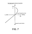
- FIG. 7 is a characteristics line drawing illustrating the rear wheel suspension geometry characteristics showing the relationship between the displacements in the back-and-forth direction and the displacements in the up-and-down direction related to the rear wheels of the vehicle shown in FIG. 5 .
- FIG. 8 is a block diagram illustrating the functions of the vehicle body vibration suppressing control computing section corresponding to FIG. 3 . It shows the vehicle body vibration estimating device in the second embodiment of the present invention.
- FIG. 9 is a flow chart illustrating the control program for estimating the vibration of the vehicle body executed by the vehicle body vibration estimating unit shown in FIG. 8 .
- FIG. 10 is a time chart illustrating the operation of the second embodiment. It compares the vehicle body vibration estimated value of the vehicle body vibration estimating device with the measured value of the vehicle body vibration in the second embodiment of the present invention.
- FIG. 11 is a block diagram illustrating the functions of the vehicle body vibration suppressing control computing section corresponding to FIG. 3 . It shows the vehicle body vibration estimating device and the vehicle body vibration suppressing controller in the third embodiment of the present invention.
- FIG. 12 is a flow chart illustrating the control program executed by the vehicle body vibration estimating section in FIG. 11 and the driving braking torque correction quantity computing section to estimate the vehicle body vibration and, at the same time, to compute the torque correction quantity for suppressing the vehicle body vibration.
- FIG. 13 is a diagram illustrating the vehicle movement model.
- FIG. 14 is a schematic system diagram illustrating the vehicle body vibration estimation process and the vehicle body vibration suppressing process in the third embodiment of the present invention.
- FIG. 15 is a block diagram illustrating the functions of the vehicle body vibration suppressing control computing section corresponding to FIG. 11 . It shows the vehicle body vibration estimating device and the vehicle body vibration suppressing controller in the fourth embodiment of the present invention.
- FIG. 16 is a flow chart corresponding to FIG. 12 . It shows the control program executed by the vehicle body vibration estimating section and the driving braking torque correction quantity computing section in FIG. 15 for computing the driving braking torque correction quantity needed for estimating the vehicle body vibration and for suppressing the vehicle body vibration.
- FIG. 17 is a block diagram illustrating the functions of the motor controller corresponding to FIG. 2 . It shows the vehicle body vibration estimating device and the vehicle body vibration suppressing controller in the fifth embodiment of the present invention.
- FIG. 18 is a block diagram illustrating the functions of the vehicle body vibration suppressing control computing section shown in FIG. 17 .
- FIG. 19 is a flow chart illustrating the control program executed by the vehicle body vibration estimating section, the vehicle body vibration state quantity complementing section and the driving braking torque correction quantity computing section shown in FIGS. 17 and 18 for estimating the vehicle body vibration and, at the same time, for computing the torque correction quantity for suppressing the vehicle body vibration.
- FIG. 20 is a diagram illustrating the movement model of the vehicle.
- FIG. 21 is a schematic system diagram illustrating the vehicle body vibration estimating process and the vehicle body vibration suppressing control process in the fifth embodiment shown in FIGS. 17 to 19 .
- FIG. 22 is a schematic system diagram illustrating the vehicle body vibration estimating process and the vehicle body vibration suppressing control process in a modified example of the vehicle body vibration estimating device and the vehicle body vibration suppressing controller shown in FIGS. 17 to 19 .
- FIG. 1 is a schematic system diagram illustrating the vehicle body vibration suppressing control system having the vehicle body vibration estimating device and the vehicle body vibration suppressing controller in the first embodiment of the present invention.
- 1 FL and 1 FR represent the left/right front wheels, respectively, and 1 RL and 1 RR represent the left/right rear wheels, respectively.
- the left/right front wheels 1 FL and 1 FR are the wheels for steering steered by steering wheel 2 .
- the left/right front wheels 1 FL and 1 FR and the left/right rear wheels 1 RL and 1 RR are suspended on the vehicle body 3 by a suspension device not shown in the drawing. This vehicle body 3 is positioned above the suspension device to form the sprung mass.
- the vehicle shown in FIG. 1 is a front wheel driving-type electric automobile that can run as the left/right front wheels 1 FL and 1 FR are driven by the motor 4 as a rotating electric motor, via a transmission unit 5 containing a differential gear unit.
- the motor controller 6 conducts DC-AC conversion for the electric power of the battery (electric charge storing unit) 7 by an inverter 8 , and it supplies the obtained AC electric power to the motor 4 under the control of the inverter 8 .
- the motor 4 is controlled so that the torque of the motor 4 is in agreement with the motor torque instruction value tTm.
- the motor controller 6 sends the power generation load to the motor 4 via the inverter 8 so that the battery 7 is not overcharged.
- the electric power generated by the regeneration brake function of the motor 4 is subject to AC-DC conversion by the inverter 8 , and the obtained DC power is charged in the battery 7 .
- the motor controller 6 carries out the vehicle body vibration estimating computing operation to be explained in detail later, and, at the same time, it carries out the vehicle body vibration suppressing computing operation to determine the motor torque instruction value tTm so as to suppress the vehicle body vibration according to the result of the estimation of the vehicle body vibration estimating computing operation.
- the front wheel speeds VwFL and VwFR are adopted as the physical quantities that represent the circumferential velocities of the left/right front wheels 1 FL and 1 FR, respectively, and the rear wheel speeds VwRL and VwRR are adopted as the physical quantities that represent the circumferential velocities of the left/right rear wheels 1 RL and 1 RR, respectively.
- the present invention is not limited to the scheme.
- the wheel speed corresponds to the wheel speed physical quantity according to the present invention
- the front wheel speed and the rear wheel speed correspond to the front wheel physical quantity and the rear wheel physical quantity according to the present invention, respectively.
- the wheel speed sensors 11 FL and 11 FR, 11 RL and 11 RR form the wheel speed physical quantity detecting means according to the present invention.
- the motor controller 6 estimates the vibration of the vehicle body 3 , and, at the same time, it determines the motor torque instruction value tTm by correcting the torque requested by the driver (attached with key of rTd, to be explained later) so that the estimated vibration of the vehicle body 3 is suppressed.
- the motor controller 6 comprises a vehicle speed computing section 20 , a requested torque computing section 21 , a vehicle body vibration suppressing control computing section 22 , a motor torque instruction value computing section 23 , and an adder 24 .
- the vehicle speed computing section 20 determines the vehicle speed VSP on the basis of front wheel speeds VwFL and VwFR and rear wheel speeds VwRL and VwRR (indicated as wheel speed Vw in FIG. 2 ) detected by the wheel speed sensors 11 FL and 11 FR, 11 RL and 11 RR (indicated by wheel speed sensor group 11 in FIG. 2 ).
- the requested torque computing section 21 carries out a computing operation by map retrieval or the like to determine the requested torque rTd (a driving torque if it is a positive value, and a brake torque it is a negative value) requested by the driver who performs driving (accelerator pedal openness APO or brake pedal stepping force BRP) on the basis of the current vehicle speed VSP.
- the vehicle body vibration suppressing control computing section 22 comprises a vehicle body vibration estimating unit 25 and a driving braking torque correction quantity computing unit 26 .
- the vehicle body vibration estimating unit 25 estimates the vibration of the vehicle body 3 from the wheel speed Vw to be explained in detail later.
- the driving braking torque correction quantity computing unit 26 computes the driving braking torque correction quantity ⁇ Td needed for suppressing the estimated vehicle body vibration.
- the vehicle body vibration estimating unit 25 is made of a vibration estimating means according to the present invention.
- the adder 24 adds the driving braking torque correction quantity ⁇ Td for suppressing the vehicle body vibration determined by the driving braking torque correction quantity computing unit 26 to the requested torque rTd determined by the requested torque computing section 21 to determine the target torque tTd that meets the request by the driver while suppressing the vehicle body vibration.
- the motor torque instruction value computing section 23 receives the torque request from another system 27 , such as a behavior controller (VDC) for controlling the vehicle behavior and a traction controller (TCS) for preventing driving slip of the driving wheels (front wheels) 1 FL and 1 FR; it limits or adjusts the target torque tTd to determine the final motor torque instruction value tTm to meet the demands.
- VDC behavior controller
- TCS traction controller
- the motor controller 6 supplies the electric power to the motor 4 from the battery 7 under control of the inverter 8 corresponding to the motor torque instruction value tTm determined as mentioned previously, so that it controls driving of the motor 4 to ensure that the torque of the motor 4 is in agreement with the motor torque instruction value tTm.
- the vehicle body vibration estimating unit 25 inside the vehicle body vibration suppressing control computing section 22 has the configuration as shown in FIG. 3 , a block diagram, to execute the control program shown in FIG. 4 to estimate the vibration of the vehicle body 3 (in this embodiment, the pitch angular velocity d ⁇ p and the bounce speed dZv as the up-and-down displacement velocity).
- step S 41 shown in FIG. 4 the vehicle body vibration estimating unit 25 reads the left/right front wheel speeds VwFL and VwFR and the left/right rear wheel speeds VwRL and VwRR as shown in FIG. 3 .
- the average front wheel speed computing section 31 and the average rear wheel speed computing section 32 (step S 42 shown in FIG. 4 ) shown in FIG. 3 .
- step S 43 shown in FIG. 4 the following operation is carried out: in the band-pass filters for extracting only the component near the vehicle body resonance frequency from the average front wheel speed VwF and the average rear wheel speed VwR, the average front wheel speed VwF and the average rear wheel speed VwR pass through them, respectively, and the vibration component fVwF near the vehicle body resonance frequency of the average front wheel speed VwF and the vibration component fVwR near the vehicle body resonance frequency of the average rear wheel speed VwR are obtained.
- the reason for the operation in which filtering process is carried out for the average front wheel speed VwF and average rear wheel speed VwR to extract only the vibration components fVwF and fVwR near the vehicle body resonance frequency is for removing the variation in the wheel speed and the noise component caused by acceleration/deceleration of the overall vehicle from the average front wheel speed VwF and the average rear wheel speed VwR, so that only the vehicle speed component that represents the vehicle body vibration is extracted.
- the vibration of the vehicle body 3 (bounce speed dZv as the up-and-down displacement speed, and pitch angular velocity d ⁇ p) is determined from the vibration component fVwF near the vehicle body resonance frequency of the average front wheel speed VwF and the vibration component fVwR near the vehicle body resonance frequency of the average rear wheel speed VwR.
- FIG. 5 is a schematic diagram illustrating the relationship between the bounce movement Zv and the pitching movement ⁇ p as the up-and-down movement at the center of gravity of the vehicle body 3 , and between the up-and-down displacements Zf at the site above the front axle of the vehicle body 3 and the up-and-down displacements Zr at the site above the rear axle of the vehicle body 3 , in the vehicle in which Lf denotes the distance between the center of gravity and the front axle and Lr denotes the distance between the center of gravity and the rear axle.
- the vehicle body 3 and the left/right rear wheels 1 RL and 1 RR make relative movement in the up-and-down direction indicated by Zr
- the vehicle body 3 and the left/right rear wheels 1 RL and 1 RR also make relative displacements in the back-and-forth direction indicated by Xtr, with the relationship shown in, for example, FIG. 7 .
- the bounce behavior computing section 35 and the pitching behavior computing section 36 (step S 44 in FIG. 4 ) in FIG. 3 that carry out prediction of the up-and-down displacements Zf and Zr correspond to the front wheel up-and-down movement estimating section and the rear wheel up-and-down movement estimating section of the present invention, respectively.
- the front wheel suspension geometry characteristics shown in FIG. 6 and the rear wheel suspension geometry characteristics shown in FIG. 7 are converted to maps as is, and are stored and pre-converted to a model. These data are adopted in predicting the up-and-down displacements Zf and Zr at the site above the front axle and the site above the rear axle of the vehicle body 3 from the displacements in the back-and-forth direction Xtf of the front wheels and the displacements in the back-and-forth direction Xtr of the rear wheels, respectively. As a result, prediction of the up-and-down displacements Zf and Zr can be made accurately.
- ⁇ p ( KgeoF ⁇ Xtf ⁇ KgeoR ⁇ Xtr )/( Lf+Lr ) (5)
- Zv ( KgeoF ⁇ Xtf ⁇ Lf+KgeoR ⁇ Xtr ⁇ Lr )/( Lf+Lr ) (6)
- d refers to the differential operator that can be adopted easily.
- d ⁇ p ( KgeoF ⁇ dXtf ⁇ KgeoR ⁇ dXtr )/( Lf+Lr ) (7)
- dZv ( KgeoF ⁇ dXtf ⁇ Lf+KgeoR ⁇ dXtr ⁇ Lr )/( Lf+Lr ) (8)
- the up-and-down bounce speed dZv and the pitch angular velocity d ⁇ p of the vehicle body 3 can be determined.
- step S 43 in FIG. 4 only the wheel speed component representing the vehicle body vibration is extracted as explained above and, from the vibration component fVwF near the vehicle body resonance frequency of the front wheel speed and the vibration component fVwR near the vehicle body resonance frequency of the rear wheel speed, the displacements Xtf in the back-and-forth direction of the left/right front wheels 1 FL and 1 FR and the displacements in the back-and-forth direction Xtr of the left/right rear wheels 1 RL and 1 RR are determined, respectively.
- the time differential values dXtf and dXtr of the displacements in the back-and-forth direction Xtf and Xtr are substituted into the equations (7) and (8), and it is possible to compute and estimate the vibration of the vehicle body 3 (up-and-down bounce speed dZv and pitch angular velocity d ⁇ p), respectively.
- the correction quantity computing section 26 shown in FIG. 3 computes and outputs the driving braking torque correction quantity ⁇ Td needed for suppressing the vehicle body vibration (up-and-down bounce speed dZv and pitch angular velocity d ⁇ p), then the results are sent to the adder 24 shown in FIG. 2 .
- the adder 24 shown in FIG. 2 corrects the requested torque rTd requested by the driver as explained above by a quantity corresponding to the driving braking torque correction quantity ⁇ Td for suppressing the vehicle body vibration as explained above, determined by the computing section 21 , and, while suppressing the vehicle body vibration, it determines the target torque tTd that can meet the demand of the driver.
- the motor torque instruction value computing section 23 of FIG. 2 limits or adjusts the target torque tTd to meet the request for torque from another system 27 , and determines the final motor torque instruction value tTm for realizing this purpose, and the result is adopted in control of driving of the motor 4 via the inverter 8 .
- driving control is carried out to suppress the vehicle body vibration (up-and-down bounce speed dZv and pitch angular velocity d ⁇ p) while meeting the requested torque rTd requested by the driver. Due to suppression of the vehicle body vibration (up-and-down bounce speed dZv and pitch angular velocity d ⁇ p), of course, comfort of riding in the vehicle can be improved; it is also possible improve the steering stability since it is possible to have a stable vehicle body posture when the vehicle turns.
- the vehicle body vibration (up-and-down bounce speed dZv and pitch angular velocity d ⁇ p) is estimated from the vibration component fVwF near the vehicle body resonance frequency of the average front wheel speed VwF and the vibration component fVwR near the vehicle body resonance frequency of the average rear wheel speed VwR.
- the vehicle body vibration is estimated from the information related to the wheel speed, that is, from the vibration component fVwF near the vehicle body resonance frequency of the average front wheel speed VwF and the vibration component fVwR near the vehicle body resonance frequency of the average rear wheel speed VwR. Consequently, it is possible to increase the precision of estimation of the vehicle body vibration (up-and-down bounce speed dZv and pitch angular velocity d ⁇ p); at the same time, it is possible not to be interfered by the influence of external disturbances.
- the front wheel suspension geometry characteristics shown in FIG. 6 and the rear wheel suspension geometry characteristics shown in FIG. 7 are converted to maps as is, and are stored and pre-converted to model. These data of maps and models are adopted in predicting the up-and-down displacements Zf and Zr at the site above the front axle and the site above the rear axle of the vehicle body 3 from the displacements in the back-and-forth direction Xtf of the front wheels and the displacements in the back-and-forth direction Xtr of the rear wheels, respectively. As a result, prediction of the up-and-down displacements Zf and Zr can be made accurately. However, this scheme is unfavorable in consideration of the cost.
- an easy scheme is adopted as follows. That is, suppose the vehicle is not moving on the flat ground, then an acceleration of 1 G is applied. In this state, the gradient KgeoF (in the case shown in FIG. 6 ) and the gradient KgeoR (in the case shown in FIG. 7 ) near the balance point (the origin as shown in FIGS. 6 and 7 ) are subject to linear approximation, and these KgofF and KgeoR are then adopted as the proportional coefficients.
- the suspension geometry characteristics of the front wheels shown in FIG. 6 and the suspension geometry characteristics of the rear wheels shown in FIG. 7 are individually adopted to predict the up-and-down displacements Zf and up-and-down displacements Zr at the site above the front axle and the site above the rear axle of the vehicle body 3 , respectively, from the back-and-forth displacement Xtf of the front wheel and the back-and-forth displacement Xtr of the rear wheel. Consequently, prediction of the up-and-down displacements Zf and Zr is accurate, and estimation of the vehicle body vibration (up-and-down bounce speed dZv and pitch angular velocity d ⁇ p) can be carried out at a high precision.
- the vibration component fVwF near the vehicle body resonance frequency of the average front wheel speed VwF and the vibration component fVwR near the vehicle body resonance frequency of the average rear wheel speed VwR are adopted.
- the vehicle body vibration is estimated using only the wheel speed information along with the vehicle body vibration without considering the variation in the wheel speed caused by acceleration/deceleration of the overall vehicle and the noise components, so that the estimation can be carried out at a high precision.
- FIGS. 8 and 9 are diagrams illustrating the vehicle body vibration estimating device related to the second embodiment of the present invention.
- FIG. 8 is a block diagram corresponding to FIG. 3 and
- FIG. 9 shows the vehicle body vibration estimating program corresponding to FIG. 4 .
- the vehicle body vibration suppressing control system is the same as that shown in FIG. 1
- the motor controller 6 is the same as that shown in FIG. 2 . Consequently, the vehicle body vibration suppressing control system and the motor controller 6 will not be explained again with reference to these drawings. In the following, only the features different from the first embodiment will be explained with reference to FIGS. 8 and 9 .
- the vehicle body vibration estimating unit 25 in the vehicle body vibration suppressing control computing section 22 has the configuration shown by the block diagram in FIG. 8 .
- the vehicle body vibration estimating unit 25 executes the control program shown in FIG. 9 to estimate the vibration of the vehicle body 3 (just as in the first embodiment, in this embodiment as well, this refers to the pitch angular velocity d ⁇ p and the up-and-down bounce speed dZv).
- step S 61 shown in FIG. 9 the vehicle body vibration estimating unit 25 reads the left/right front wheel speeds VwFL and VwFR and left/right rear wheel speeds VwRL and VwRR as shown in FIG. 8 .
- the vibration of the vehicle body 3 (up-and-down bounce speed dZv and pitch angular velocity d ⁇ p as the up-and-down displacement speeds) is determined from the average front wheel speed VwF and the average rear wheel speed VwR that will be explained below.
- the displacements Xtf in the back-and-forth direction of the left/right front wheels 1 FL and 1 FR and the displacements in the back-and-forth direction Xtr of the left/right rear wheels 1 RL and 1 RR are determined from the average front wheel speed VwF and average rear wheel speed VwR; these displacements in the back-and-forth direction Xtf and Xtr of the front wheels and rear wheels are adopted to perform computing using the equation (5) to determine the pitching movement ⁇ p of the vehicle body 3 , which is then time differentiated to get the pitch angular velocity f ⁇ p of the vehicle body 3 .
- step S 64 as shown in FIG. 9 the pitch angular velocity f ⁇ p is fed through the band-pass filter for extracting only the component of the pitch angular velocity f ⁇ p of the vehicle body 3 near the resonance frequency of the vehicle body to determine the final pitch angular velocity d ⁇ p as the vibration component of the pitch angular velocity f ⁇ p near the resonance frequency of the vehicle body.
- the reason for the operation in which the filtering process is carried out for the pitch angular velocity f ⁇ p of the vehicle body 3 to extract only the component near the resonance frequency of the vehicle body is as follows. That is, the pitch angular velocity f ⁇ p contains the variation in the wheel speed caused by acceleration/deceleration of the entirety of the vehicle and the noise components, and these components should be removed from the pitch angular velocity f ⁇ p to obtain the final pitch angular velocity d ⁇ p that represents only the vehicle body vibration.
- the final pitch angular velocity d ⁇ p is returned to the pitching behavior computing section 54 , and the pitching behavior computing section 54 (step S 65 as shown in FIG. 9 ) subtracts the average front wheel speed VwF and average rear wheel speed VwR from the pitch angular velocity d ⁇ p to correct the pitch angular velocity f ⁇ p by excluding the influence caused by the error in the pitch angular velocity.
- the final pitch angular velocity d ⁇ p is also sent to the bounce behavior computing section 53 , which then uses it to carry out the same correction as in step S 65 shown in FIG. 9 for the average front wheel speed VwF and average rear wheel speed VwR.
- the displacements Xtf in the back-and-forth direction of the left/right front wheels 1 FL and 1 FR and the displacements in the back-and-forth direction Xtr of the left/right rear wheels 1 RL and 1 RR are determined; it then uses these displacements in the back-and-forth direction Xtf and Xtr of the front wheels and rear wheels to determine the up-and-down bounce movement Zv of the vehicle body 3 by computing using the equation (6), followed by time differentiation to determine the up-and-down bounce speed fZv of the vehicle body 3 .
- step S 67 shown in FIG. 9 only the component near the resonance frequency of the vehicle body is extracted from the up-and-down bounce speed fZv of the vehicle body 3 .
- the component of the up-and-down bounce speed fZv passes through the band-pass filter, so that it is possible to determine the final up-and-down bounce speed dZv as the component of vibration of the up-and-down bounce speed fZv near the resonance frequency of the vehicle body.
- the up-and-down bounce speed fZv originally contains the variation in the wheel speed caused by acceleration/deceleration of the entirety of the vehicle and the noise components. It is thus necessary to remove these components from the up-and-down bounce speed fZv to obtain the final up-and-down bounce speed dZv representing only the vehicle body vibration.
- the correction quantity computing section 26 for the driving braking torque shown in FIG. 8 can compute the driving braking torque correction quantity ⁇ Td needed for suppressing the vehicle body vibration (up-and-down bounce speed dZv and pitch angular velocity d ⁇ p), and output it to the adder 24 as shown in FIG. 2 .
- the adder 24 shown in FIG. 2 corrects the requested torque rTd requested by the driver determined as mentioned previously at the computing unit 21 by a quantity corresponding to only the driving braking torque correction quantity ⁇ Td to determine the target torque tTd that can suppress the vehicle body vibration and can meet the request of the driver.
- the motor torque instruction value computing section 23 shown in FIG. 2 limits or adjusts the target torque tTd to meet the request for the torque from another system 27 to determine the final motor torque instruction value tTm for realizing this purpose. The result is then sent via the inverter 8 to drive the motor 4 .
- the motor 4 is driven under control to suppress the vehicle body vibration (up-and-down bounce speed dZv and pitch angular velocity d ⁇ p) and to meet the requested torque rTd requested by the driver, so that it is possible to suppress the vehicle body vibration (up-and-down bounce speed dZv and pitch angular velocity d ⁇ p) and to improve the comfort of riding in the vehicle; it is also possible to ensure a stable posture of the vehicle body when the vehicle turns, so that it is possible to improve the steering stability, too.
- the vehicle body vibration (up-and-down bounce speed fZv and pitch angular velocity f ⁇ p) is estimated by computing from the average front wheel speed VwF and the average rear wheel speed VwR.
- the vehicle body vibration is estimated from the information related to the wheel speed, so that it is possible to increase the estimation precision, and, at the same time, it is possible to exclude the influence of the external disturbances.
- the average front wheel speed VwF and the average rear wheel speed VwR adopted in estimating the vehicle body vibration are corrected by subtracting the pitch angular velocity d ⁇ p to exclude the influence caused by the error in the pitch angular velocity in estimating the vehicle body vibration. Consequently, it is possible to exclude the influence caused by the error in the pitch angular velocity, and it is possible to increase the precision of estimation of the vehicle body vibration.
- the vehicle body vibration estimating devices have been explained for the case in which they are adopted in the vehicle body vibration suppressing control via the driving braking force operation of an electric automobile with the motor 4 as the sole power source.
- the scheme can also be adopted in the vehicle body vibration suppressing controller via engine control of the vehicle with an internal combustion engine or another engine as the power source; the scheme can also be adopted in the vehicle body vibration suppressing controller via the operation of a suspension device instead of the driving braking force operation of a motor or an engine.
- the wheel speed information adopted in estimating the vehicle body vibration is not limited to the average front wheel speed VwF and average rear wheel speed VwR as shown in the drawing; it may also be adopted in estimating the vehicle body vibration on the basis of a 4-wheel model where the wheel speeds VwFL and VwFR, VwRL and VwRR are individually adopted.
- the estimated vehicle body vibration is not limited to the pitch angular velocity d ⁇ p and up-and-down bounce speed dZv of the example shown in the drawing. It is also easy to estimate the roll movement and other vibrations of the vehicle body.
- the frequency component indicating the vehicle body vibration (the back-and-forth movement component of the wheels with respect to 3) is fetched from the average front wheel speed VwF and the average rear wheel speed VwR
- a band-pass filter extracting only the component near the resonance frequency of the vehicle body from the average front wheel speed VwF and the average rear wheel speed VwR is adopted to obtain the vibration component fVwF near the vehicle body resonance frequency of the average front wheel speed VwF and the vibration component fVwR near the vehicle body resonance frequency of the average rear wheel speed VwR, which are adopted in estimating the vehicle body vibration.
- the information it is also possible to use the following wheel speed information.
- the following scheme may also be adopted: a means for accurately detecting or estimating the vehicle speed as the speed of the vehicle body 3 with respect to the ground is provided; the errors between the vehicle speed and the average front wheel speed VwF and the average rear wheel speed VwR are adopted instead of the vibration component fVwF near the vehicle body resonance frequency of the average front wheel speed VwF and the vibration component fVwR near the vehicle body resonance frequency of the average rear wheel speed VwR in estimating the vehicle vibration.
- this scheme is unfavorable with respect to the precision in estimating the vehicle body vibration, and the scheme whereby the vibration component fVwF near the vehicle body resonance frequency of the average front wheel speed VwF and the vibration component fVwR near the vehicle body resonance frequency of the average rear wheel speed VwR obtained using the band-pass filter as that in the first embodiment are adopted is better for practical application.
- the band-pass filtering process by carrying out the band-pass filtering process, only the component near the resonance frequency of the vehicle body is extracted from the up-and-down bounce speed fZv and the pitch angular velocity f ⁇ p of the vehicle body 3 determined from the average front wheel speed VwF and the average rear wheel speed VwR, and the final up-and-down bounce speed dZv and the pitch angular velocity d ⁇ p representing only the vehicle body vibration are obtained.
- a differentiator is arranged so that when the vehicle body vibration (up-and-down bounce speed dZv and pitch angular velocity d ⁇ p) is estimated, the average front wheel speed VwF and the average rear wheel speed VwR are differentiated to be converted to the wheel acceleration information, and, on the basis of the wheel acceleration information from the differentiator, the up-and-down bounce speed dZv and the pitch angular velocity d ⁇ p are estimated.
- FIG. 11 shows the vehicle body vibration estimating device and vehicle body vibration suppressing controller related to the third embodiment. It is a block diagram illustrating the functions of the vehicle body vibration suppressing control computing section 22 corresponding to that shown in FIG. 3 .
- FIG. 12 is a flow chart illustrating the control program executed by the vehicle body vibration suppressing control computing section 22 shown in FIG. 11 for estimating the vehicle body vibration and, at the same time, for computing the torque correction quantity for suppressing the vehicle body vibration.
- the vehicle body vibration suppressing control system is the same as that shown in FIG. 1
- the motor controller 6 is the same as that shown in FIG. 2 . Consequently, explanation of the vehicle body vibration suppressing control system and the motor controller 6 on the basis of these drawings will not be repeated, and, in the following, only the features different from those in the first embodiment will be explained with reference to FIGS. 11 and 12 .
- the vehicle body vibration estimating unit 25 and the correction quantity computing section 26 inside the vehicle body vibration suppressing control computing section 22 have the configuration shown in the block diagram in FIG. 11 . While the control program shown in FIG. 12 is executed to estimate the vibration of the vehicle body 3 (in this embodiment, the pitch angle f ⁇ p, the pitch angular velocity df ⁇ p, as well as the up-and-down bounce quantity fZv as the up-and-down displacement quantity, and the bounce speed dfZv), at the same time, it is used to compute the driving braking torque correction quantity ⁇ Td needed for suppressing the estimated vehicle body vibration (f ⁇ p, df ⁇ p, fZv, dfZv).
- the vehicle body vibration estimating unit 25 is comprised a wheel speed standard vehicle body vibration estimating unit 25 a (the wheel speed physical quantity standard vehicle body vibration estimating means in this invention) and a driving braking force standard vehicle body vibration estimating unit 25 b (the driving braking force standard vehicle body vibration estimating means in this invention).
- step S 41 shown in FIG. 12 the wheel speed standard vehicle body vibration estimating unit 25 a shown in FIG. 11 is adopted to read the left/right front wheel speeds VwFL and VwFR and the left/right rear wheel speeds VwRL and VwRR.
- the wheel speed standard vehicle body vibration estimating unit 25 a is also comprised of an average front wheel speed computing section 31 and an average rear wheel speed computing section 32 , a front wheel band-pass filter processing section 33 , a rear wheel band-pass filter processing section 34 , a bounce behavior computing section 35 and a pitching behavior computing section 36 .
- the front wheel band-pass filter processing section 33 and the rear wheel band-pass filter processing section 34 shown in FIG. 11 are then adopted to filter the average front wheel speed VwF and the average rear wheel speed VwR so that only the components near the resonance frequency of the vehicle body are extracted from the average front wheel speed VwF and the average rear wheel speed VwR to obtain the vibration component fVwF near the vehicle body resonance frequency of the average front wheel speed VwF and the vibration component fVwR near the vehicle body resonance frequency of the average rear wheel speed VwR.
- the bounce behavior computing section 35 and the pitching behavior computing section 36 shown in FIG. 11 (step S 44 shown in FIG. 12 ) then determine the up-and-down bounce speed dZv and the pitch angular velocity d ⁇ p of the vehicle body 3 as the wheel speed standard vehicle body vibration from the vibration component fVwF near the vehicle body resonance frequency of the average front wheel speed VwF and the vibration component fVwR near the vehicle body resonance frequency of the average rear wheel speed VwR as follows.
- step S 44 the method of determining the wheel speed standard vehicle body vibration (up-and-down bounce speed dZv and pitch angular velocity d ⁇ p of the vehicle body 3 ) from the wheel speed vibration components fVwF and fVwR is the same as that described with reference to FIGS. 5-7 .
- step S 43 shown in FIG. 11 From the vibration component fVwF near the vehicle body resonance frequency of the average front wheel speed and the vibration component fVwR near the vehicle body resonance frequency of the average rear wheel speed obtained using the band-pass filter processing sections 33 and 34 shown in FIG. 11 (step S 43 shown in FIG.
- the displacements Xtf in the back-and-forth direction of the left/right front wheels 1 FL and 1 FR and the displacements in the back-and-forth direction Xtr of the left/right rear wheels 1 RL and 1 RR are determined, respectively, and by substituting the time differential values dXtf and dXtf of these displacements in the back-and-forth direction Xtf and Xtr into the equations (7) and (8), the wheel speed standard vehicle body vibration (up-and-down bounce speed dZv and pitch angular velocity d ⁇ p) can be computed and estimated, respectively.
- step S 45 shown in FIG. 12 the driving braking force standard vehicle body vibration estimating unit 25 b shown in FIG. 11 reads the requested torque rTd determined by the computing section 21 shown in FIG. 2 as the driving braking torque of the vehicle.
- the driving braking force standard vehicle body vibration estimating unit 25 b has a vehicle model 37 .
- step S 46 shown in FIG. 12 the wheel speed standard vehicle body vibration (up-and-down bounce speed dZv and pitch angular velocity d ⁇ p) is taken as the observer input, and the vehicle model 37 is adopted in estimating the state by the observer from the requested torque rTd (the driving braking torque of the vehicle) to compute and estimate the driving braking force standard vehicle body vibration (up-and-down bounce speed fZv, up-and-down bounce speed dfZv, pitch angle f ⁇ p, pitch angular velocity df ⁇ p).
- FIG. 13 is a diagram illustrating the basic vehicle model 37 that forms the observer.
- Lf represents the distance between the center of gravity and the front axle in the wheel base L
- Ksf and Cf represent the spring constant and vibration-damping coefficient of the front wheel suspension device
- Ksr and Cr represent the spring constant and the vibration-damping coefficient of the rear wheel suspension device
- M represents the mass of the vehicle body 3
- Ip represents the pitching inertial moment of the vehicle body 3 , when a driving braking torque rTd is applied on this vehicle.
- the driving braking force standard vehicle body vibration (up-and-down bounce speed fZv and pitch angle f ⁇ p) at the center of gravity of the vehicle body 3 is represented by both the up-and-down displacements Zf at the site above the front axle of the vehicle body 3 and the up-and-down displacements Zr at the site above the rear axle of the vehicle body 3 .
- the motion equations related to the driving braking force standard vehicle body vibration can be represented as follows, with the differential operator simply represented as “d”.
- M ⁇ ddfZv ⁇ 2 Ksf ( fZv+Lf ⁇ f ⁇ p ) ⁇ 2 Cf ( dfZv+Lf ⁇ df ⁇ p ) ⁇ 2 Ksr ( fZv ⁇ Lr ⁇ f ⁇ p ) ⁇ 2 Cr ( dfZv ⁇ Lr ⁇ df ⁇ p ) (9)
- Ip ⁇ ddf ⁇ p ⁇ 2 Lf ⁇ Ksf ( fZv+Lf ⁇ f ⁇ p )+ Cf ( dfZv+Lf ⁇ df ⁇ p ) ⁇ +2 Lr ⁇ Ksr ( fZv ⁇ Lr ⁇ f ⁇ p )+ Cr ( dfZv ⁇ Lr ⁇ df ⁇ p ) ⁇ + rTd (10)
- step S 46 shown in FIG. 12 the driving braking force standard vehicle body vibration estimating unit 25 b shown in FIG. 11 uses the vehicle model 37 to estimate the state by the observer from the requested torque rTd (the driving braking torque of the vehicle), and the driving braking force standard vehicle body vibration x (up-and-down bounce quantity fZv, up-and-down bounce speed dfZv, pitch angle f ⁇ p, pitch angular velocity df ⁇ p) is computed and estimated.
- the driving braking force standard vehicle body vibration x up-and-down bounce quantity fZv, up-and-down bounce speed dfZv, pitch angle f ⁇ p, pitch angular velocity df ⁇ p
- the wheel speed standard vehicle body vibration (up-and-down bounce speed dZv and pitch angular velocity d ⁇ p) is also input as observer input from the computing sections 35 and 36 , and the vehicle model 37 is adopted in computing the driving braking force standard vehicle body vibration x (up-and-down bounce quantity fZv, up-and-down bounce speed dfZv, pitch angle f ⁇ p, pitch angular velocity df ⁇ p) from the requested torque rTd (the driving braking torque of the vehicle).
- the driving braking force standard vehicle body vibration x up-and-down bounce quantity fZv, up-and-down bounce speed dfZv, pitch angle f ⁇ p, pitch angular velocity df ⁇ p
- the driving braking force standard vehicle body vibration estimating unit 25 b shown in FIG. 11 also takes the wheel speed standard vehicle body vibration (up-and-down bounce speed dZv and pitch angular velocity d ⁇ p) as the observer input and, on the basis of vehicle model 37 , the driving braking force standard vehicle body vibration x (up-and-down bounce quantity fZv, up-and-down bounce speed dfZv, pitch angle f ⁇ p, pitch angular velocity df ⁇ p) is computed from the requested torque rTd (the driving braking torque of the vehicle).
- the driving braking force standard vehicle body vibration estimating unit 25 b (the vehicle model 37 ) can meet both the demand on a robust property resistance to external disturbances and the demand on a high stability.
- the driving braking force standard vehicle body vibration x from the requested torque rTd (the driving braking torque of the vehicle), which is the cause of the vehicle body vibration, before generation of the vehicle body vibration instead of after the generation of the vehicle body vibration, it is possible to conduct a feed forward estimation of the driving braking force standard vehicle body vibration x (up-and-down bounce quantity fZv, up-and-down bounce speed dfZv, pitch angle f ⁇ p, pitch angular velocity df ⁇ p) as the final vehicle body vibration.
- the driving braking force standard vehicle body vibration x up-and-down bounce quantity fZv, up-and-down bounce speed dfZv, pitch angle f ⁇ p, pitch angular velocity df ⁇ p
- step S 47 shown in FIG. 12 the correction quantity computing section 26 shown in FIG. 11 computes the driving braking torque correction quantity ⁇ Td needed for suppressing the driving braking force standard vehicle body vibration x (up-and-down bounce quantity fZv, up-and-down bounce speed dfZv, pitch angle f ⁇ p, pitch angular velocity df ⁇ p) as the final vehicle body vibration as follows.
- the driving braking force standard vehicle body vibration x (up-and-down bounce quantity fZv, up-and-down bounce speed dfZv, pitch angle f ⁇ p, pitch angular velocity df ⁇ p) is multiplied by the regulator gain Kr indicated by key “ 38 ” in FIG. 11 , and the linear sum of the product values obtained as the results is taken as the driving braking torque correction quantity ⁇ Td.
- the regulator gain Kr is defined as the weight applied for adjusting the degree in suppressing (alleviating) the up-and-down bounce quantity fZv, up-and-down bounce speed dfZv, pitch angle f ⁇ p, and pitch angular velocity df ⁇ p as the final vehicle body vibration. This is preferred since it can increase the degree of freedom in the design.
- the regulator gain Kr may be composed of multiple regulator gains that are set by changing the weighting pattern of the suppression (alleviating) degree for each set of the vehicle body vibration, that is, for the up-and-down bounce quantity fZv, up-and-down bounce speed dfZv, pitch angle f ⁇ p, pitch angular velocity df ⁇ p.
- the sum of the products between the multiple regulator gains and the up-and-down bounce quantity fZv, up-and-down bounce speed dfZv, pitch angle f ⁇ p, pitch angular velocity df ⁇ p may be taken as the driving braking torque correction quantity ⁇ Td.
- the tuning gains are set corresponding to the multiple regulator gains, with the sum of the products of the up-and-down bounce quantity fZv, up-and-down bounce speed dfZv, pitch angle f ⁇ p, pitch angular velocity df ⁇ p, the multiple regulator gains, and the tuning gains being taken as the driving braking torque correction quantity ⁇ Td.
- the driving braking torque correction quantity ⁇ Td determined by the driving braking torque correction quantity computing section 26 shown in FIG. 11 (step S 47 shown in FIG. 12 ) is sent to the adder 24 shown in FIG. 2 .
- the adder 24 corrects the requested torque rTd requested by the driver and determined by the computing section 21 as mentioned previously by the driving braking torque correction quantity ⁇ Td for suppressing the vehicle body vibration, so that the target torque tTd that can meet the request of the driver is determined while suppressing the vehicle body vibration.
- the motor torque instruction value computing section 23 shown in FIG. 2 limits or adjusts the target torque tTd to meet the request for torque by another system 27 , so that the final motor torque instruction value tTm for realizing this is determined, and it is then sent via the inverter 8 to control driving of the motor 4 .
- FIG. 14 shows the flow of the vehicle body vibration estimation and the vehicle body vibration suppressing control in this embodiment.
- A, B, C, and D represent the A, B, C, and D matrix when the vehicle model shown in FIG. 13 is represented by the state equations, and Ko represents the observer gain with respect to the observer input (dZv, d ⁇ p, dfZv, df ⁇ p).
- the motor 4 is subjected to driving control to meet the requested torque rTd requested by the driver while suppressing the driving braking force standard vehicle body vibration x (up-and-down bounce quantity fZv, up-and-down bounce speed dfZv, pitch angle f ⁇ p, pitch angular velocity df ⁇ p).
- the driving braking force standard vehicle body vibration x (up-and-down bounce quantity fZv, up-and-down bounce speed dfZv, pitch angle f ⁇ p, pitch angular velocity df ⁇ p) can be suppressed, it is possible to improve the comfort of riding in the vehicle; it is also possible to have a stable posture of the vehicle body when the vehicle turns, and it is possible to improve the steering stability.
- the wheel speed standard vehicle body vibration (up-and-down bounce speed dZv and pitch angular velocity d ⁇ p) is estimated from the vibration component fVwF near the vehicle body resonance frequency of the average front wheel speed VwF and the vibration component fVwR near the vehicle body resonance frequency of the average rear wheel speed VwR.
- the wheel speed standard vehicle body vibration (up-and-down bounce speed dZv and pitch angular velocity d ⁇ p) is taken as the observer input and, from the requested torque rTd (driving braking force of the vehicle), the vehicle model 37 is used to estimate the driving braking force standard vehicle body vibration x (up-and-down bounce quantity fZv, up-and-down bounce speed dfZv, pitch angle f ⁇ p, pitch angular velocity df ⁇ p) as the final vehicle body vibration. Consequently, the following operation and effects can be realized.
- the wheel speed standard vehicle body vibration (up-and-down bounce speed dZv and pitch angular velocity d ⁇ p) from the information related to the wheel speeds, that is, the vibration component fVwF near the vehicle body resonance frequency of the average front wheel speed VwF and the vibration component fVwR near the vehicle body resonance frequency of the average rear wheel speed VwR. Consequently, it is possible to increase the precision of estimation.
- the vehicle model 37 is adopted to estimate the driving braking force standard vehicle body vibration x (up-and-down bounce quantity fZv, up-and-down bounce speed dfZv, pitch angle f ⁇ p, pitch angular velocity df ⁇ p) as the final vehicle body vibration from the requested torque rTd (the driving braking force of the vehicle).
- This driving braking force standard vehicle body vibration (the final vehicle body vibration) x can also have an excellent, high precision with respect to the robust property resistance to the external disturbances, and the effect by the vibration suppressing control can become significant.
- the wheel speed standard vehicle body vibration (up-and-down bounce speed dZv and pitch angular velocity d ⁇ p) is taken as the final vehicle body vibration as is, and the wheel speed standard vehicle body vibration (up-and-down bounce speed dZv and pitch angular velocity d ⁇ p) is that after generation of the vehicle body vibration, when feed forward control is conducted for the vehicle body vibration suppressing control, the estimation of the final vehicle body vibration is too slow, which is unfavorable.
- the wheel speed standard vehicle body vibration (up-and-down bounce speed dZv and pitch angular velocity d ⁇ p) is taken as the observer input
- the driving braking force standard vehicle body vibration x (up-and-down bounce quantity fZv, up-and-down bounce speed dfZv, pitch angle f ⁇ p, pitch angular velocity df ⁇ p) estimated using the vehicle model 37 from the driving braking force rTd of the vehicle before the generation of the vehicle body vibration is taken as the final vehicle body vibration. Consequently, even when the feed forward control is carried out for the vehicle body vibration suppressing control, estimation of the final vehicle body vibration is not very slow.
- the driving braking torque correction quantity ⁇ Td needed for alleviating the final vehicle body vibration x is computed; this driving braking torque correction quantity ⁇ Td is used to correct the driving braking force rTd of the vehicle.
- the vehicle body vibration can always be alleviated.
- FIGS. 15 and 16 show the vehicle body vibration estimating device and the vehicle body vibration suppressing controller related to the fourth embodiment of the present invention.
- FIG. 15 is a block diagram of the vehicle body vibration suppressing control computing section 22 corresponding to FIG. 11 and FIG. 16 shows the vehicle body vibration estimation and the vehicle body vibration suppressing control program executed by the vehicle body vibration suppressing control computing section 22 . It is a flow chart corresponding to FIG. 12 .
- the vehicle body vibration suppressing control system is the same as that shown in FIG. 1
- the motor controller 6 is the same as that shown in FIG. 2 . Consequently, explanation of the vehicle body vibration suppressing control system and the motor controller 6 on the basis of these drawings will not be repeated, and, in the following, only the features different from those in the third embodiment will be explained with reference to FIGS. 15 and 16 .
- the vehicle body vibration estimating unit 25 inside the vehicle body vibration suppressing control computing section 22 has the configuration shown in the block diagram in FIG. 15 . While the control program shown in FIG. 16 is executed by the vehicle body vibration estimating unit 25 to estimate the vibration of the vehicle body 3 (in this embodiment, just as in the third embodiment, the pitch angle f ⁇ p, the pitch angular velocity df ⁇ p, the up-and-down bounce quantity fZv, and the up-and-down bounce speed dfZv).
- step S 61 shown in FIG. 16 the wheel speed standard vehicle body vibration estimating unit 25 a inside the vehicle body vibration estimating unit 25 reads the left/right front wheel speeds VwFL and VwFR and the left/right rear wheel speeds VwRL and VwRR as shown in FIG. 15 .
- the bounce behavior computing section 53 shown in FIG. 15 determines the displacements Xtf in the back-and-forth direction of the left/right front wheels 1 FL and 1 FR (see FIG. 5 ) and the displacements in the back-and-forth direction Xtr of the left/right rear wheels 1 RL and 1 RR (see FIG. 5 ) with respect to the vehicle body from the average front wheel speed VwF and the average rear wheel speed VwR.
- These displacements in the back-and-forth direction Xtf and Xtr of the front wheels and rear wheels are then used to compute the up-and-down bounce movement Zv (see FIG. 5 ) of the vehicle body 3 by the equation (6). It is then time differentiated to determine the up-and-down bounce speed aZv of the vehicle body 3 .
- the pitching behavior computing section 54 shown in FIG. 15 determines the displacements Xtf in the back-and-forth direction of the left/right front wheels 1 FL and 1 FR (see FIG. 5 ) and the displacements in the back-and-forth direction Xtr of the left/right rear wheels 1 RL and 1 RR (see FIG. 5 ) with respect to the vehicle body from the average front wheel speed VwF and the average rear wheel speed VwR, and these displacements in the back-and-forth direction Xtf and Xtr of the front wheels and rear wheels are used to determine the pitching movement ⁇ p of the vehicle body 3 (see FIG. 5 ) by computing using the equation (5), and it is time differentiated to determine the pitch angular velocity ⁇ p of the vehicle body 3 .
- the band-pass filter processing section 55 shown in FIG. 15 has the up-and-down bounce speed aZv pass through the band-pass filter that extracts only the component near the resonance frequency of the vehicle body from the up-and-down bounce speed aZv of the vehicle body 3 determined by the bounce behavior computing section 53 shown in FIG. 15 (step S 63 shown in FIG. 16 ) to determine the up-and-down bounce speed dZv (the wheel speed standard vehicle body vibration) as the vibration component of the up-and-down bounce speed aZv near the resonance frequency of the vehicle body.
- dZv the wheel speed standard vehicle body vibration
- the reason for extracting only the component near the resonance frequency of the vehicle body by the filtering process for the up-and-down bounce speed aZv of the vehicle body 3 is as follows. That is, the wheel speed standard up-and-down bounce speed aZv contains the variation in the wheel speed caused by acceleration/deceleration of the entirety of the vehicle and the noise components. Consequently, it is necessary to remove them from the up-and-down bounce speed a Zv, so that the wheel speed standard up-and-down bounce speed dZv represents only the vehicle body vibration.
- step S 64 the pitch angular velocity a ⁇ p determined by the pitching behavior computing section 54 shown in FIG. 15 (step S 63 shown in FIG. 16 ) is then fed through the band-pass filter for extracting only the component of the pitch angular velocity a ⁇ p of the vehicle body 3 near the resonance frequency of the vehicle body to determine the component of the pitch angular velocity a ⁇ p near the resonance frequency of the vehicle body (the wheel speed standard vehicle body vibration).
- the pitch angular velocity a ⁇ p contains the variation in the wheel speed caused by acceleration/deceleration of the entirety of the vehicle and the noise components, and they should be excluded from the pitch angular velocity a ⁇ p to have the wheel speed standard pitch angular velocity d ⁇ p representing only the vehicle body vibration.
- step S 65 shown in FIG. 16 the driving braking force standard vehicle body vibration estimating unit 25 b shown in FIG. 15 reads the requested torque rTd determined by the computing section 21 shown in FIG. 2 as the driving braking torque of the vehicle.
- the driving braking force standard vehicle body vibration estimating unit 25 b is the same as that shown in FIG. 11 , and it has a vehicle model 37 .
- step S 66 shown in FIG. 16 the wheel speed standard vehicle body vibration (up-and-down bounce speed dZv and pitch angular velocity d ⁇ p) is taken as the observer input, and the vehicle model 37 is adopted to carry out the state estimation by the observer from the requested torque rTd (the driving braking torque of the vehicle), so that the driving braking force standard vehicle body vibration (up-and-down bounce quantity fZv, up-and-down bounce speed dfZv, pitch angle f ⁇ p, pitch angular velocity df ⁇ p) is computed and estimated.
- the driving braking force standard vehicle body vibration estimating unit 25 b shown in FIG. 15 uses the vehicle model 37 to carry out the state estimation by the observer from the requested torque rTd (driving braking torque of the vehicle), and to compute and estimate the driving braking force standard vehicle body vibration x (up-and-down bounce quantity fZv, up-and-down bounce speed dfZv, pitch angle f ⁇ p, pitch angular velocity df ⁇ p):
- the wheel speed standard vehicle body vibration (up-and-down bounce speed dZv and pitch angular velocity d ⁇ p) from the computing parts 55 and 56 [inconsistent key] is also taken as the observer input and it uses the vehicle model 37 to compute the driving braking force standard vehicle body vibration x (up-and-down bounce quantity fZv, up-and-down bounce speed dfZv, pitch angle f ⁇ p, pitch angular velocity df ⁇ p) from the requested torque rTd (the driving braking torque of the vehicle).
- the driving braking force standard vehicle body vibration x up-and-down bounce quantity fZv, up-and-down bounce speed dfZv, pitch angle f ⁇ p, pitch angular velocity df ⁇ p
- the driving braking force standard vehicle body vibration estimating unit 25 b shown in FIG. 15 also takes the wheel speed standard vehicle body vibration (up-and-down bounce speed dZv and pitch angular velocity d ⁇ p) as the observer input, and, on the basis of vehicle model 37 , the driving braking force standard vehicle body vibration x (up-and-down bounce quantity fZv, up-and-down bounce speed dfZv, pitch angle f ⁇ p, pitch angular velocity df ⁇ p) is computed from the requested torque rTd (the driving braking torque of the vehicle).
- the driving braking force standard vehicle body vibration estimating unit 25 b (the vehicle model 37 ) can meet both the demand on a robust property to external disturbances and the demand on a high stability.
- the driving braking force standard vehicle body vibration x is estimated from the requested torque rTd (the driving braking torque of the vehicle) as the cause of the vehicle body vibration
- the driving braking force standard vehicle body vibration x up-and-down bounce quantity fZv, up-and-down bounce speed dfZv, pitch angle f ⁇ p, pitch angular velocity df ⁇ p
- the driving braking force standard vehicle body vibration x up-and-down bounce quantity fZv, up-and-down bounce speed dfZv, pitch angle f ⁇ p, pitch angular velocity df ⁇ p
- step S 67 shown in FIG. 16 the driving braking torque correction quantity computing section 26 shown in FIG. 15 computes the driving braking torque correction quantity ⁇ Td needed for suppressing the driving braking force standard vehicle body vibration x (up-and-down bounce quantity fZv, up-and-down bounce speed dfZv, pitch angle f ⁇ p, pitch angular velocity df ⁇ p) as the final vehicle body vibration as follows.
- the driving braking force standard vehicle body vibration x (up-and-down bounce quantity fZv, up-and-down bounce speed dfZv, pitch angle f ⁇ p, pitch angular velocity df ⁇ p) is multiplied by the regulator gain Kr (set similarly as in the third embodiment) indicated by key “ 38 ” in FIG. 15 , and the linear sum of the product values obtained as the results is taken as the driving braking torque correction quantity ⁇ Td.
- the driving braking torque correction quantity ⁇ Td determined by the driving braking torque correction quantity computing section 26 shown in FIG. 15 (step S 67 shown in FIG. 16 ) is sent to the adder 24 shown in FIG. 2 .
- the adder 24 corrects the requested torque rTd requested by the driver determined as explained above by the computing section 21 by a quantity corresponding to the driving braking torque correction quantity ⁇ Td, and, while suppressing the vehicle body vibration, it determines the target torque tTd that can meet the demand of the driver.
- the motor torque instruction value computing section 23 shown in FIG. 2 limits or adjusts the target torque tTd to meet the request for torque from another system 27 , and determines the final motor torque instruction value tTm for realizing this objective, with the result being adopted in the control of driving of the motor 4 via the inverter 8 .
- driving control is carried out to suppress the driving braking force standard vehicle body vibration x (up-and-down bounce quantity fZv, up-and-down bounce speed dfZv, pitch angle f ⁇ p, pitch angular velocity df ⁇ p) while meeting the requested torque rTd requested by the driver.
- the wheel speed standard vehicle body vibration (up-and-down bounce speed aZv and pitch angular velocity a ⁇ p) are estimated from the average front wheel speed VwF and average rear wheel speed VwR.
- step S 64 the wheel speed standard vehicle body vibration (up-and-down bounce speed dZv and pitch angular velocity d ⁇ p) is estimated.
- the vehicle model 37 is adopted to determine the driving braking force standard vehicle body vibration x (up-and-down bounce quantity fZv, up-and-down bounce speed dfZv, pitch angle f ⁇ p, pitch angular velocity df ⁇ p) as the final vehicle speed.
- the driving braking force standard vehicle body vibration x up-and-down bounce quantity fZv, up-and-down bounce speed dfZv, pitch angle f ⁇ p, pitch angular velocity df ⁇ p
- the wheel speed standard vehicle body vibration (up-and-down bounce speed dZv and pitch angular velocity d ⁇ p) is estimated from the information related to the wheel speed, so that the estimation precision is high.
- the vehicle model 37 is adopted to estimate the driving braking force standard vehicle body vibration x (up-and-down bounce quantity fZv, up-and-down bounce speed dfZv, pitch angle f ⁇ p, pitch angular velocity df ⁇ p).
- the driving braking force standard vehicle body vibration (the final vehicle speed) x can be obtained with an excellent robust property with respect to the external disturbances and with a high precision, and the effects of the vibration suppressing control are excellent.
- the wheel speed standard vehicle body vibration (up-and-down bounce speed dZv and pitch angular velocity d ⁇ p) is not taken as the final vehicle speed as it is. Instead, it is taken as the observer input, with the vehicle model 37 being adopted to estimate the driving braking force standard vehicle body vibration x (up-and-down bounce quantity fZv, up-and-down bounce speed dfZv, pitch angle f ⁇ p, pitch angular velocity df ⁇ p) from the driving braking force rTd of the vehicle before generation of the vehicle body vibration. Consequently, even when the vehicle body vibration suppressing control is carried out as feed forward control, there is still no delay in the estimation of the vehicle body vibration; there is also no problem that would hamper realization of the vehicle body vibration suppressing control.
- the motor 4 alone is taken as the power source for the electric automobile, for which the vehicle body vibration suppressing control is carried out by the driving braking force operation.
- the scheme can also be adopted in the vehicle body vibration suppressing controller via engine control of a vehicle containing an internal combustion engine or other engine as the power source, and the scheme can also be adopted in the vehicle body vibration suppressing controller via the operation of a suspension device instead of the driving braking force operation of a motor or an engine.
- the wheel speed information adopted in estimating the vehicle body vibration is not limited to the average front wheel speed VwF and average rear wheel speed VwR as shown in the drawing; it may also be adopted in estimating the vehicle body vibration on the basis of a 4-wheel model where the wheel speeds VwFL and VwFR, VwRL and VwRR are individually adopted.
- the wheel speed standard vehicle body vibration as the observer input to the vehicle model 37 is not limited to the pitch angular velocity d ⁇ p and up-and-down bounce speed dZv in the third and fourth embodiments. It is also easy to estimate the roll movement and other vibrations of the vehicle body.
- the frequency component indicating the vehicle body vibration (the back-and-forth movement component of the wheels with respect to the vehicle body 3 ) is fetched from the average front wheel speed VwF and the average rear wheel speed VwR
- a band-pass filter extracting only the component near the resonance frequency of the vehicle body from the average front wheel speed VwF and the average rear wheel speed VwR is adopted to obtain the vibration component fVwF near the vehicle body resonance frequency of the average front wheel speed VwF and the vibration component fVwR near the vehicle body resonance frequency of the average rear wheel speed VwR, which are adopted in estimating the wheel speed standard vehicle body vibration (pitch angular velocity d ⁇ p and up-and-down bounce speed dZv).
- the information data it is also possible to use the following wheel speed information.
- the following scheme may also be adopted: a means for accurately detecting or estimating the vehicle speed as the speed of the vehicle body 3 with respect to the ground is arranged; the errors between the vehicle speed and the average front wheel speed VwF and the average rear wheel speed VwR are adopted instead of the vibration component fVwF near the vehicle body resonance frequency of the average front wheel speed VwF and the vibration component fVwR near the vehicle body resonance frequency of the average rear wheel speed VwR in estimating the wheel speed standard vehicle body vibration (pitch angular velocity d ⁇ p and up-and-down bounce speed dZv).
- this scheme is unfavorable with respect to the precision in estimating the vehicle body vibration, so it is practical to use the scheme whereby the vibration component fVwF near the vehicle body resonance frequency of the average front wheel speed VwF and the vibration component fVwR near the vehicle body resonance frequency of the average rear wheel speed VwR obtained using the band-pass filter as that in the third embodiment are adopted.
- the requested torque rTd determined by the computing section 21 in FIG. 2 is adopted as the driving braking force for estimating the driving braking force standard vehicle body vibration x (up-and-down bounce quantity fZv, up-and-down bounce speed dfZv, pitch angle f ⁇ p, pitch angular velocity df ⁇ p).
- the present invention is not limited to the scheme. Any state quantity that can represent the driving braking force of the vehicle may be adopted as well.
- the requested torque of the vehicle body is computed from the operation of the actuator and, of course, the obtained requested torque can be used as the driving braking force of the vehicle.
- FIG. 17 shows the vehicle body vibration estimating device and the vehicle body vibration suppressing controller related to the fifth embodiment of the present invention. It is a block diagram illustrating the functions of the motor controller 6 corresponding to FIG. 2 .
- FIG. 18 is a diagram illustrating in detail the vehicle body vibration suppressing control computing section 22 shown in FIG. 17 . It is a block diagram illustrating the functions corresponding to FIG. 3 .
- FIG. 19 is a flow chart illustrating the control program executed by the vehicle body vibration suppressing control computing section 22 shown in FIGS. 17 and 18 to estimate the vehicle body vibration and, at the same time, to compute the torque correction quantity for suppressing the vehicle body vibration.
- the vehicle body vibration suppressing system is the same as that shown in FIG. 1 . Consequently, explanation of the vehicle body vibration suppressing control system on the basis of this figure will not be repeated. In the following, only the features different from the first embodiment will be explained with reference to FIGS. 17 to 19 .
- the motor controller 6 estimates the vibration of the vehicle body 3 , and, at the same time, it corrects the requested torque rTd requested by the driver to determine the motor torque instruction value tTm so as to suppress the estimated vibration of the vehicle body 3 . Consequently, in addition to input of the accelerator pedal openness APO and the brake pedal stepping force BRP, the following physical quantities representing the vehicle body vibration are also input: left/right front wheel speeds VwFL and VwFR (front wheel physical quantities) as the circumferential velocities of the left/right front wheels 1 FL and 1 FR, and the left/right rear wheel speeds VwRL and VwRR (rear wheel physical quantities) as the circumferential velocities of the left/right rear wheels 1 RL and 1 RR.
- VwFL and VwFR front wheel physical quantities
- VwRL and VwRR rear wheel physical quantities
- the physical quantities representing the vehicle body vibration are not limited to the physical quantities.
- the wheel speeds VwFL and VwFR, VwRL and VwRR correspond to the vehicle body vibration physical quantities in the present invention.
- the wheel speed sensors 11 FL and 11 FR, 11 RL and 11 RR form the vehicle body vibration physical quantity detecting means in this invention.
- the motor controller 6 consists of a vehicle speed computing section 20 , a requested torque computing section 21 , a vehicle body vibration suppressing control computing section 22 , a motor torque instruction value computing section 23 , and an adder 24 .
- a vehicle body vibration state quantity complementing section 29 is included between the vehicle body vibration estimating unit 25 and the driving braking torque correction quantity computing section 26 in the vehicle body vibration suppressing control computing section 22 .
- the vehicle body vibration suppressing control computing section 22 consists of the vehicle body vibration estimating unit 25 , the driving braking torque correction quantity computing section 26 , and the vehicle body vibration state quantity complementing section 29 .
- the vehicle speed computing section 20 determines the vehicle speed VSP from the left/right front wheel speeds VwFL and VwFR and the left/right rear wheel speeds VwRL and VwRR (indicated by wheel speed Vw in FIG. 17 ,) detected by the wheel speed sensors 11 FL and 11 FR, 11 RL and 11 RR (indicated by wheel speed sensor group 11 in FIG. 17 ).
- the requested torque computing section 21 determines the requested torque rTd (if positive, it represents a driving torque; if negative, it represents a braking torque) requested in the manipulation by the driver for driving on the basis of the current vehicle speed VSP obtained by the computing unit 20 mentioned above (accelerator pedal openness APO and brake pedal stepping force BRP) from the accelerator pedal openness APO and the brake pedal stepping force BRP detected by the sensors 13 , 14 .
- the vehicle body vibration estimating unit 25 the vehicle body vibration state quantity complementing section 29 and the driving braking torque correction quantity computing section 26 that form the vehicle body vibration suppressing control computing section 22 :
- the vehicle body vibration estimating unit 25 estimates the vibration of the vehicle body 3 (or the vehicle body vibration state quantity) to be explained in detail later from the wheel speed Vw,
- the vehicle body vibration state quantity complementing section 29 computes the other vehicle body vibration (another vehicle body vibration state quantity) from the vehicle body vibration (or the vehicle body vibration state quantity) estimated by the vehicle body vibration estimating unit 25 .
- the vehicle body vibration estimating unit 25 corresponds to the vehicle body vibration state quantity computing means
- the vehicle body vibration state quantity complementing section 29 corresponds to the vehicle body vibration state quantity complementing means in this invention.
- the vehicle body vibration state quantity complementing section 29 feeds the computed another vehicle body vibration (another vehicle body vibration state quantity) together with the vehicle body vibration (or vehicle body vibration state quantity) from the vehicle body vibration estimating unit 25 to the driving braking torque correction quantity computing section 26 .
- the driving braking torque correction quantity computing section 26 computes the driving braking torque correction quantity ⁇ Td needed for suppressing the vehicle body vibration (or the vehicle body vibration state quantity) fed from the vehicle body vibration estimating unit 25 via the vehicle body vibration state quantity complementing section 29 , and the other vehicle body vibration (another vehicle body vibration state quantity) from the vehicle body vibration state quantity complementing section 29 .
- the driving braking torque correction quantity computing section 26 corresponds to the driving braking force correction quantity computing means in the present invention.
- the adder 24 corrects the requested torque rTd requested by the driver determined by the requested torque computing section 21 by adding the driving braking torque correction quantity ⁇ Td determined by the driving braking torque correction quantity computing section 26 to it, so that it can determine the target torque tTd that meets the request of the driver while suppressing the vehicle body vibration.
- the adder 24 forms the driving braking force correcting means according to the present invention.
- the motor torque instruction value computing section 23 receives the torque request from another system 27 , such as the behavior controller (VDC) that controls the behavior of the vehicle or the traction controller (TCS) for preventing slip in driving of the driving wheels (the front wheels) 1 FL and 1 FR or the like, and it limits or adjusts the target torque tTd to meet the request, so that the final motor torque instruction value tTm for realizing the operation is determined.
- VDC behavior controller
- TCS traction controller
- the motor controller 6 has the electric power fed from the valve 7 to the motor 4 under control of the inverter 8 , so that the motor 4 is driven under control to ensure that the torque of the motor 4 is in agreement with the motor torque instruction value tTm.
- the vehicle body vibration estimating unit 25 , the vehicle body vibration state quantity complementing section 29 , and the driving braking torque correction quantity computing section 26 inside the vehicle body vibration suppressing control computing section 22 have the configuration shown in the block diagram in FIG. 18 .
- the vehicle body vibration suppressing control computing section executes the control program shown in FIG. 19 to estimate the vibration of the vehicle body 3 (in this application example, the pitching movement ⁇ p, the pitch angular velocity d ⁇ p, the up-and-down bounce movement Zv, and the up-and-down bounce speed dZv), and, at the same time, it computes the driving braking torque correction quantity ⁇ Td needed for suppressing the estimated vehicle body vibration ( ⁇ p, d ⁇ p, Zv, dZv).
- the vehicle body vibration estimating unit 25 consists of the average front wheel speed computing section 51 , the average rear wheel speed computing section 52 , the bounce behavior computing section 53 , the pitching behavior computing section 54 , and the band-pass filter processing sections 55 and 56 .
- step S 61 shown in FIG. 19 the average front wheel speed computing section 51 and the average rear wheel speed computing section 52 read the left/right front wheel speeds VwFL and VwFR and the left/right rear wheel speeds VwRL and VwRR.
- the method for the bounce behavior computing section 53 and the pitching behavior computing section 54 (step S 63 in FIG. 19 ) to determine the up-and-down bounce speed dZv(F) and the pitch angular velocity d ⁇ p(F) of the vehicle body 3 as the vehicle body vibration state quantity from the average front wheel speed VwF and the average rear wheel speed VwR is the same as the method shown in FIGS. 5 to 7 .
- the computing sections 51 and 52 shown in FIG. 18 determines the displacements Xtf in the back-and-forth direction of the left/right front wheels 1 FL and 1 FR and the displacements in the back-and-forth direction Xtr of the left/right rear wheels 1 RL and 1 RR including the vehicle body vibration.
- step S 64 shown in FIG. 19 only the component near the resonance frequency of the vehicle body is extracted from the up-and-down bounce speed dZv(F) of the vehicle body 3 determined by the bounce behavior computing section 53 of FIG. 18 (step S 63 shown in FIG. 19 ).
- the component of the up-and-down bounce speed dZv(F) passes through the band-pass filter, so that it is possible to determine the up-and-down bounce speed dZv(F) as the component of vibration of the up-and-down bounce speed dZv (or the vehicle body state quantity) near the resonance frequency of the vehicle body.
- the up-and-down bounce speed dZv(F) originally contains the variation in the wheel speed caused by acceleration/deceleration of the entirety of the vehicle and the noise components. It is thus necessary to remove these components from the up-and-down bounce speed dZv(F) to obtain the final up-and-down bounce speed dZv representing only the vehicle body vibration.
- step S 64 shown in FIG. 19 only the component near the resonance frequency of the vehicle body is extracted from the pitch angular velocity d ⁇ p(F) of the vehicle body 3 determined by the pitching behavior computing section 54 of FIG. 18 (step S 63 shown in FIG. 19 ).
- step S 63 shown in FIG. 19 only the component of the pitch angular velocity d ⁇ p(F) passes through the band-pass filter, so that it is possible to determine the pitch angular velocity d ⁇ p(F) as the component of pitch angular velocity d ⁇ p (or the vehicle body state quantity) near the resonance frequency of the vehicle body.
- the pitch angular velocity d ⁇ p(F) originally contains the variation in the wheel speed caused by acceleration/deceleration of the entirety of the vehicle and the noise components. It is thus necessary to remove these components from the pitch angular velocity d ⁇ p(F) to obtain the final up-and-down bounce speed pitch angular velocity d ⁇ p representing only the vehicle body vibration.
- the driving braking torque correction quantity for the vehicle body vibration suppression be multiplied with the gain with respect to the vehicle body vibration, and it is thus necessary to set the gain for suppressing the vehicle body vibration.
- the vehicle model shown in FIG. 20 is used, the drawing of which mechanically summarizes the relationship between the driving braking torque and the vehicle body vibration of the vehicle.
- FIG. 20 is a diagram illustrating the vehicle model 37 .
- Lf represents the distance between the center of gravity and the front axle in the wheel base L
- Lr represents the distance of the center of gravity and the rear axle
- Ksf and Cf represent the spring constant and vibration-damping coefficient of the front wheel suspension device, respectively
- Ksr and Cr represent the spring constant and the vibration-damping coefficient of the rear wheel suspension device, respectively
- M represents the mass of the vehicle body 3
- Ip represents the pitching inertial moment of the vehicle body 3 ,
- the up-and-down bounce quantity Zv and the pitch angle ⁇ p at the center of gravity of the vehicle body 3 are shown together with the up-and-down displacements Zf at the site above the front axle of the vehicle body 3 and the up-and-down displacements Zr at the site above the rear axle of the vehicle body 3 .
- weighting is carried out on these four types of vehicle body vibration state quantities ( ⁇ p, d ⁇ p, Zv, dZv), and, on the basis of the weighting, the regulator gain for suppressing the vehicle body vibration state quantities ( ⁇ p, d ⁇ p, Zv, dZv) is designed and adopted in the vehicle body vibration suppressing control.
- the vehicle body vibration estimating unit 25 of FIGS. 17 and 18 among the four types of vehicle body vibration state quantities (pitch angle ⁇ p, pitch angular velocity d ⁇ p, up-and-down bounce quantity Zv, and up-and-down bounce velocity dZv), only two types, that is, the pitch angular velocity d ⁇ p and the up-and-down bounce speed dZv (or the vehicle body vibration state quantity) can be estimated, while for the other types, that is, the pitch angle ⁇ p and the up-and-down bounce quantity Zv, there is no way to make vibration suppressing control to actively suppress them.
- the pitch angle ⁇ p and the up-and-down bounce quantity Zv there is no way to make vibration suppressing control to actively suppress them.
- the vehicle body vibration state quantity complementing section 29 shown in FIG. 18 (step S 65 in FIG. 19 ) can determine the pitch angle ⁇ p and the up-and-down bounce quantity Zv as the other vehicle body vibration state quantities from the pitch angular velocity d ⁇ p and the up-and-down bounce speed dZv, so that the complemented vehicle body vibration state quantity complementing process is carried out.
- integrators 26 a and 26 b are provided in the vehicle body vibration state quantity complementing section 29 shown in FIG. 18 .
- the integrator 26 a integrates the up-and-down bounce speed dZv to obtain the up-and-down bounce quantity Zv
- the integrator 26 b integrates the pitch angular velocity d ⁇ p to obtain the pitch angle ⁇ p.
- the vehicle body vibration state quantity complementing section 29 works as follows in step S 66 shown in FIG. 19 . That is, the up-and-down bounce speed dZv and the pitch angular velocity d ⁇ p from the vehicle body vibration estimating unit 25 are sent as it is to the driving braking torque correction quantity computing section 26 , and the up-and-down bounce quantity Zv and pitch angle ⁇ p determined by integrating them are sent to the driving braking torque correction quantity computing section 26 , too. That is, the four types of the vehicle body vibration x ( ⁇ p, d ⁇ p, Zv, dZv) are sent to the driving braking torque correction quantity computing section 26 .
- step S 67 shown in FIG. 19 the driving braking torque correction quantity computing section 26 shown in FIG. 18 computes the driving braking torque correction quantity ⁇ Td needed for suppressing the four types of vehicle body vibration x ( ⁇ p, d ⁇ p, Zv, dZv).
- the vehicle body vibration x (up-and-down bounce quantity Zv, up-and-down dZv, pitch angle ⁇ p, pitch angular velocity d ⁇ p) is multiplied with the regulator gain Kr indicated by key 38 in FIG. 18 , and the linear sum of the product values obtained as the results is taken as the driving braking torque correction quantity ⁇ Td.
- the regulator gain Kr is defined as the weight applied for adjusting the degree in suppressing (alleviating) the up-and-down bounce quantity Zv, the up-and-down bounce speed dZv, the pitch angle ⁇ p and the pitch angular velocity d ⁇ p. This is preferred as it can increase the degree of freedom in the design.
- the regulator gain Kr may be composed of multiple regulator gains that are set by changing the weighting pattern of the suppression (alleviating) degree for each set of the vehicle body vibration, that is, for each of the up-and-down bounce quantity Zv, up-and-down bounce speed dZv, pitch angle ⁇ p, and pitch angular velocity d ⁇ p.
- the sum of the products between the multiple regulator gains and the up-and-down bounce quantity Zv, up-and-down bounce speed dZv, pitch angle ⁇ p, and pitch angular velocity d ⁇ p may be taken as the driving braking torque correction quantity ⁇ Td.
- the driving braking torque correction quantity computing section 26 shown in FIG. 18 (step S 67 shown in FIG. 19 ) sends the driving braking torque correction quantity ⁇ Td determined above to the adder 24 shown in FIG. 7 .
- the adder 24 corrects the requested torque rTd requested by the driver determined by the requested torque computing section 21 by a quantity corresponding to the driving braking torque correction quantity ⁇ Td to determine the target torque tTd that can meet the request of the driver while suppressing the vehicle body vibration.
- the motor torque instruction value computing section 23 shown in FIG. 17 limits or adjusts the target torque tTd to meet the request for the torque by another system 27 to determine the final motor torque instruction value tTm for realizing this operation, and the result is sent via the inverter 8 for controlling driving of the motor 4 .
- FIG. 21 is a diagram illustrating the flow of the operation in estimating the vehicle body vibration and control of the vehicle body vibration in this embodiment as explained above.
- step S 65 shown in FIG. 19 integrates the pitch angular velocity d ⁇ p and the up-and-down bounce speed dZv to get the pitch angle ⁇ p and the up-and-down bounce quantity Zv, for the conventional integration operation, the operation load is too heavy to be actually adopted, and the computed state quantity is divergent.
- the signal measured or estimated on an actual vehicle usually has an offset (0 point offset) and noise components. If integration is carried out for such signal without paying attention, the integration error increases, and the control may become divergent.
- the integration result may be offset, which is undesirable.
- the integration time constant T be at least longer than the vehicle body resonance period, and at least the information of the resonance period be able to accumulate it reliably.
- multiple regulator gains Kr 1 and Kr 2 are prepared, the tuning gains G 1 and G 2 are set with respect to the regulator gains Kr 1 and Kr 2 , and the sum of the integration values of the up-and-down bounce quantity Zv, the up-and-down bounce speed dZv, the pitch angle ⁇ p, the pitch angular velocity d ⁇ p, the multiple regulator gains Kr 1 and Kr 2 , and the tuning gains G 1 and G 2 is taken as the driving braking torque correction quantity ⁇ Td.
- the various vehicle body vibration state quantities also have influences on the other vehicle body vibration state quantities. Consequently, it is difficult to find out the optimum value in hand tuning.
- multiple regulator gains having a certain degree of balance (such as the gain Kr 1 for suppressing the bounce behavior and the gain Kr 2 for suppressing the pitching behavior) are prepared and, when tuning is carried out for an actual vehicle, it is possible to apply weighting with the tuning gains G 1 and G 2 on the regulator gains Kr 1 and Kr 2 , respectively, so that it is possible to efficiently realize the gain tuning.
- the motor 4 is controlled in driving to meet the requested torque rTd requested by the driver while suppressing the vehicle body vibration x (up-and-down bounce quantity Zv, up-and-down bounce speed dZv, pitch angle ⁇ p, and pitch angular velocity d ⁇ p).
- Suppression of the vehicle body vibration x (up-and-down bounce quantity Zv, up-and-down bounce speed dZv, pitch angle ⁇ p, and pitch angular velocity d ⁇ p) can naturally improve the comfort of riding in the vehicle, so it is also possible to realize a stable posture of the vehicle body and to improve the steering stability when the vehicle turns.
- the vehicle body vibration estimating unit 25 adopted in the present embodiment estimates the vehicle body vibration from the wheel speeds and other speed information free of variation caused by degradation over time and the increase/decrease in the number of the occupants riding in the vehicle in place of the driving braking force and external disturbance torque that vary corresponding to the degradation over time and increase/decrease in the number of the occupants riding in the vehicle. Consequently, it is only possible to estimate two types of the vehicle body vibration, that is, the up-and-down bounce speed dZv and the pitch angular velocity d ⁇ p.
- the vehicle body vibration state quantity complementing section 29 is arranged to complement by determining the up-and-down bounce quantity Zv by integrating the up-and-down bounce speed dZv, and, at the same time, by determining the pitch angle ⁇ p by integrating the pitch angular velocity d ⁇ p.
- the four types of vehicle body vibration of up-and-down bounce speed dZv, the up-and-down bounce quantity Zv, the pitch angular velocity d ⁇ p, and the pitch angle ⁇ p are adopted in carrying out the vehicle body vibration suppressing control.
- the integrators 26 a and 26 b for integration are pseudo integrators with the prescribed time constant T and having the transmission function G(s) represented by the equation (13).
- the old information continues to be deleted corresponding to the prescribed time constant T, so that it is possible to prevent accumulation of the integration error and the divergence caused by the accumulation of the integration error; it is also possible to make accurate computing of the up-and-down bounce quantity Zv and the up-and-down bounce quantity Zv.
- the integration time constant T is selected to be at least longer than the vehicle body resonance period.
- the up-and-down bounce speed dZv(F) and pitch angular velocity d ⁇ p(F) are estimated from the average front wheel speed VwF and the average rear wheel speed VwR.
- the up-and-down bounce speed dZv and the pitch angular velocity d ⁇ p are estimated from the average front wheel speed VwF and the average rear wheel speed VwR without variation caused by the degradation over time and increase/decrease in the number of the occupants riding in the vehicle, it is possible to increase the estimation precision without being influenced by the degradation over time and increase/decrease in the number of the occupants riding in the vehicle, and it is possible to significantly improve the effect of the vibration suppressing control.
- the pseudo integrators represented by the transmission function G(s) represented by the equation (13) having the prescribed time constant T set for it is adopted to determine the pitch angle ⁇ p and the up-and-down bounce quantity Zv with the pitch angular velocity d ⁇ p and the up-and-down bounce speed dZv as the pseudo integrations.
- the pseudo integrators are adopted as in this embodiment, during the pseudo integration on the basis of the time constant T, the old information is kept being deleted, so that it is possible to prevent accumulation of the integration error, and it is possible to avoid the problem of divergence of the computed pitch angle ⁇ p and the up-and-down bounce quantity Zv.
- the integration time constant T is at least over the vehicle body resonance period, at least the information of the resonance period can be accumulated reliably, and it is possible to avoid the problem that due to insufficiency of the information, it is impossible to compute the pitch angle ⁇ p and the up-and-down bounce quantity Zv.
- the driving braking torque correction quantity computing section 26 shown in FIG. 18 determines the driving braking torque correction quantity ⁇ Td for suppressing the vehicle body vibration, as shown in FIG. 21 , the regulator gain Kr is multiplied to the vehicle body vibration x (up-and-down bounce quantity Zv, up-and-down bounce speed dZv, pitch angle ⁇ p, and pitch angular velocity d ⁇ p) and the linear sum of the product values obtained as a result of the computing is taken as the driving braking torque correction quantity ⁇ Td.
- the regulator gain Kr is determined as the weighting corresponding to the degree in suppressing (alleviating) each of the up-and-down bounce quantity Zv, up-and-down bounce speed dZv, pitch angle ⁇ p, and pitch angular velocity d ⁇ p.
- the regulator gain Kr comprises multiple regulator gains set for variation in the weighting pattern for the degree of suppressing (alleviating) of the up-and-down bounce quantity Zv, up-and-down bounce speed dZv, pitch angle ⁇ p, and pitch angular velocity d ⁇ p, and
- the sum of the multiple regulator gains and the integration values of the up-and-down bounce quantity Zv, up-and-down bounce speed dZv, pitch angle ⁇ p, and pitch angular velocity d ⁇ p is taken as the driving braking torque correction quantity ⁇ Td.
- the driving braking torque correction quantity computing section 26 shown in FIG. 18 determines the driving braking torque correction quantity ⁇ Td for suppressing the vehicle body vibration
- multiple regulator gains gain Kr 1 for suppressing the bounce behavior, and gain Kr 2 for suppressing the pitching behavior
- the tuning gains G 1 and G 2 are set with respect to the regulator gains Kr 1 and Kr 2
- the multiple regulator gains Kr 1 and Kr 2 , and the tuning gains G 1 and G 2 is taken as the driving braking torque correction quantity ⁇ Td
- the vehicle body vibration state quantity complementing section 29 uses the integration of the up-and-down bounce speed dZv and the pitch angular velocity d ⁇ p of the vehicle body 3 to determine and complement the up-and-down bounce quantity Zv and the pitch angle ⁇ p.
- the vehicle body vibration suppressing device when used for suppressing the up-and-down bounce acceleration ddZv and the pitching angular acceleration dd ⁇ p, the vehicle body vibration state quantity complementing section 29 has a differentiator, and, by differentiating the up-and-down bounce speed dZv and the pitch angular velocity d ⁇ p of the vehicle body 3 , it determines the up-and-down bounce acceleration ddZv and the pitching angular acceleration dd ⁇ p, which are then adopted in computing the driving braking torque correction quantity ⁇ Td.
- the up-and-down bounce speed dZv and the pitch angular velocity d ⁇ p of the vehicle body 3 as well as the up-and-down bounce quantity Zv and the pitch angle ⁇ p determined by integrating the quantities are adopted as it is in computing the driving braking torque correction quantity ⁇ Td.
- the up-and-down bounce speed dZv, the pitch angular velocity d ⁇ p, the up-and-down bounce quantity Zv and the pitch angle ⁇ p are subject to a filtering process to remove the steady component or the low frequency component, or they are subject to the filtering process to remove the high frequency component, and the results are adopted in computing the driving braking torque correction quantity ⁇ Td.
- the noises and offset can be removed from the up-and-down bounce speed dZv, the pitch angular velocity d ⁇ p, the up-and-down bounce quantity Zv and the pitch angle ⁇ p, so that it is possible to avoid the problem that the noise and offset are further amplified in the later process; thus leading to an adverse influence on the vehicle body vibration suppressing control.
- the pitch angular velocity d ⁇ p and the up-and-down bounce speed dZv as the vehicle body vibration state quantities are computed from the average front wheel speed VwF and the average rear wheel speed VwR as the vehicle body vibration physical quantities.
- a vehicle body vibration state quantity detecting means is arranged for directly or indirectly detecting the pitch angular velocity d ⁇ p and the up-and-down bounce speed dZv, with the results detected by this means being taken as the vehicle body vibration state quantities.
- the driving braking torque correction quantity computing section 26 multiplies the regulator gain Kr (Kr 1 and Kr 2 ) to the vehicle body vibration x (up-and-down bounce speed dZv, pitch angular velocity d ⁇ p, up-and-down bounce quantity Zv and pitch angle ⁇ p) to determine the driving braking torque correction quantity.
- the present invention is not limited to the scheme.
- the vehicle body vibration x (up-and-down bounce speed dZv, pitch angular velocity d ⁇ p, up-and-down bounce quantity Zv and pitch angle ⁇ p) is converted to the up-and-down movement physical quantities at any two points (such as the site above the front axle and the site above the rear axle) on the vehicle body 3 , and the driving braking torque correction quantity needed for alleviating at least one of the up-and-down movement physical quantities at these two points being determined and adopted in the vehicle body vibration suppressing control.
- the vehicle body vibration x (up-and-down bounce speed dZv, pitch angular velocity d ⁇ p, up-and-down bounce quantity Zv and pitch angle ⁇ p) is converted to the relative up-and-down movement physical quantities of the left/right front wheels 1 FL and 1 FR and the left/right rear wheels 1 RL and 1 RR with respect to the vehicle body 3 , with the driving braking force correction quantity needed for alleviating at least one of the up-and-down movement physical quantities of the front wheels and rear wheels being determined and adopted in the vehicle body vibration suppressing control.
Landscapes
- Engineering & Computer Science (AREA)
- Transportation (AREA)
- Mechanical Engineering (AREA)
- Physics & Mathematics (AREA)
- Combustion & Propulsion (AREA)
- Chemical & Material Sciences (AREA)
- Automation & Control Theory (AREA)
- General Physics & Mathematics (AREA)
- Theoretical Computer Science (AREA)
- Power Engineering (AREA)
- Life Sciences & Earth Sciences (AREA)
- Sustainable Energy (AREA)
- Sustainable Development (AREA)
- Mathematical Physics (AREA)
- Quality & Reliability (AREA)
- General Engineering & Computer Science (AREA)
- Control Of Driving Devices And Active Controlling Of Vehicle (AREA)
Abstract
Description
Zf=Zv+θp·Lf (1)
Zr=Zv−θp·Lr (2)
Zf=KgeoF·Xtf (3)
Zr=KgeoR·Xtr (4)
θp=(KgeoF·Xtf−KgeoR·Xtr)/(Lf+Lr) (5)
Zv=(KgeoF·Xtf·Lf+KgeoR·Xtr·Lr)/(Lf+Lr) (6)
dθp=(KgeoF·dXtf−KgeoR·dXtr)/(Lf+Lr) (7)
dZv=(KgeoF·dXtf·Lf+KgeoR·dXtr·Lr)/(Lf+Lr) (8)
M·ddfZv=−2Ksf(fZv+Lf·fθp)−2Cf(dfZv+Lf·dfθp)−2Ksr(fZv−Lr·fθp)−2Cr(dfZv−Lr·dfθp) (9)
Ip·ddfθp=−2Lf{Ksf(fZv+Lf·fθp)+Cf(dfZv+Lf·dfθp)}+2Lr{Ksr(fZv−Lr·fθp)+Cr(dfZv−Lr·dfθp)}+rTd (10)
M·ddfZv=−2Ksf(Zv+Lf·θp)−2Cf(dZv+Lf−dfθp)−2Ksr(Zv−Lr·θp)−2Cr(dZv−Lr·dθp) (11)
Ip·ddfθp=−2Lf{Ksf(Zv+Lf·θp)+Cf(dZv+Lf·dθp)}+2Lr{Ksr(Zv−Lr·θp)+Cr(dZv−Lr·dθp)}+rTd (12)
G(s)=T/(Ts+1) (13)
Claims (56)
Applications Claiming Priority (7)
| Application Number | Priority Date | Filing Date | Title |
|---|---|---|---|
| JP2010-189106 | 2010-08-26 | ||
| JP2010189067A JP5652054B2 (en) | 2010-08-26 | 2010-08-26 | Body vibration estimation device |
| JP2010-189067 | 2010-08-26 | ||
| JP2010-189027 | 2010-08-26 | ||
| JP2010189027A JP5652053B2 (en) | 2010-08-26 | 2010-08-26 | Vehicle vibration estimation device and vehicle system vibration control device using the same |
| JP2010189106A JP5652055B2 (en) | 2010-08-26 | 2010-08-26 | Vehicle vibration estimation device and vehicle system vibration control device using the same |
| PCT/JP2011/068910 WO2012026441A1 (en) | 2010-08-26 | 2011-08-23 | Device for estimating vehicle body vibration and controller for suppressing vehicle body vibration using same |
Publications (2)
| Publication Number | Publication Date |
|---|---|
| US20130231838A1 US20130231838A1 (en) | 2013-09-05 |
| US8880292B2 true US8880292B2 (en) | 2014-11-04 |
Family
ID=45723440
Family Applications (1)
| Application Number | Title | Priority Date | Filing Date |
|---|---|---|---|
| US13/812,088 Active 2031-10-28 US8880292B2 (en) | 2010-08-26 | 2011-08-23 | Device for estimating vehicle body vibration and controller for suppressing vehicle body vibration using same |
Country Status (4)
| Country | Link |
|---|---|
| US (1) | US8880292B2 (en) |
| EP (1) | EP2610605B1 (en) |
| CN (1) | CN103189729B (en) |
| WO (1) | WO2012026441A1 (en) |
Cited By (6)
| Publication number | Priority date | Publication date | Assignee | Title |
|---|---|---|---|---|
| US20130253764A1 (en) * | 2012-03-23 | 2013-09-26 | Nissan Motor Co., Ltd. | Control apparatus for vehicle and control method for vehicle |
| US20150046034A1 (en) * | 2012-05-14 | 2015-02-12 | Nissan Motor Co., Ltd. | Vehicle control device, and vehicle control method |
| US20170267049A1 (en) * | 2014-08-19 | 2017-09-21 | Kyb Corporation | Suspension Control Apparatus, Suspension Control Method, and Program |
| US9855933B2 (en) | 2013-05-16 | 2018-01-02 | Jaguar Land Rover Limited | Vehicle speed control system |
| US10703359B2 (en) | 2017-01-27 | 2020-07-07 | Ford Global Technologies, Llc | Controlling vehicle orientation |
| US20220063420A1 (en) * | 2020-08-25 | 2022-03-03 | Hyundai Mobis Co., Ltd. | Method and apparatus for controlling driving force for dual-motor-equipped vehicle |
Families Citing this family (30)
| Publication number | Priority date | Publication date | Assignee | Title |
|---|---|---|---|---|
| JP5857781B2 (en) * | 2012-02-15 | 2016-02-10 | 日産自動車株式会社 | Vehicle vibration control device using electric motor |
| JP6193264B2 (en) * | 2012-12-25 | 2017-09-06 | 住友重機械工業株式会社 | Motor drive device for electric forklift and electric forklift using the same |
| JP5850035B2 (en) * | 2013-12-12 | 2016-02-03 | トヨタ自動車株式会社 | Control device for hybrid vehicle |
| DE102014200435A1 (en) * | 2014-01-13 | 2015-07-16 | Ford Global Technologies, Llc | Method for operating a brake system of a motor vehicle and brake system for a motor vehicle |
| DE102014001515A1 (en) * | 2014-02-07 | 2015-08-13 | Schenck Process Gmbh | vibrating machine |
| JP6153493B2 (en) * | 2014-04-25 | 2017-06-28 | ヤマハ発動機株式会社 | Roll angle estimation device and transport equipment |
| CN104228606B (en) * | 2014-08-30 | 2016-08-24 | 重庆长安汽车股份有限公司 | A kind of pure electric automobile eliminates the control method of vehicle shake |
| JP6248970B2 (en) * | 2015-03-11 | 2017-12-20 | トヨタ自動車株式会社 | Body state quantity estimation device |
| JP6245217B2 (en) * | 2015-05-19 | 2017-12-13 | トヨタ自動車株式会社 | Vehicle state quantity estimation device |
| EP3313701B1 (en) * | 2015-06-26 | 2024-08-14 | C.R.F. Società Consortile per Azioni | Method for reducing noise in a driveline of a motor vehicle |
| JP6578146B2 (en) * | 2015-07-10 | 2019-09-18 | Ntn株式会社 | Slip control device |
| JP6233608B2 (en) * | 2015-10-13 | 2017-11-22 | トヨタ自動車株式会社 | Vehicle driving force control device |
| US10870356B2 (en) * | 2015-10-26 | 2020-12-22 | Mitsubishi Electric Corporation | Vehicle-speed control device |
| JP6233609B2 (en) | 2015-10-27 | 2017-11-22 | トヨタ自動車株式会社 | Vehicle driving force control device |
| DE102016206604B4 (en) * | 2016-04-19 | 2020-01-23 | Volkswagen Aktiengesellschaft | Control device and method for regulating a damper hardness of a vibration damper of a motor vehicle |
| JP6640659B2 (en) * | 2016-06-14 | 2020-02-05 | 株式会社日立製作所 | Control device for power converter, power conversion system, compressor drive system, flywheel power generation system, and control method for power converter |
| CN106528988B (en) * | 2016-10-27 | 2019-04-23 | 桂林电子科技大学 | Design Method of Robust Controller for Vehicle Active Suspension with Limited Band Constraints |
| DE102016123421B4 (en) | 2016-12-05 | 2024-02-15 | Dr. Ing. H.C. F. Porsche Aktiengesellschaft | Method and control device for adjusting the damping force of a shock absorber |
| DE102017202750A1 (en) * | 2017-02-21 | 2018-08-23 | Volkswagen Aktiengesellschaft | Control system and method for damping vibrations of a drive train of a motor vehicle and motor vehicle with such a control system |
| JP6627829B2 (en) | 2017-07-20 | 2020-01-08 | トヨタ自動車株式会社 | Vehicle vibration control device |
| DE102017217413B4 (en) * | 2017-09-29 | 2022-02-10 | Continental Teves Ag & Co. Ohg | Method for determining an operating variable of a drum brake, drum brake arrangements, evaluation device and storage medium |
| JP7028649B2 (en) | 2018-01-10 | 2022-03-02 | 日立Astemo株式会社 | Vehicle, vehicle motion state estimation device and vehicle motion state estimation method |
| JP7224897B2 (en) | 2018-12-21 | 2023-02-20 | 日立Astemo株式会社 | Vehicle motion state estimation device, vehicle motion state estimation method, and vehicle |
| CN112977080B (en) * | 2019-12-16 | 2022-08-26 | 华为技术有限公司 | Drive anti-slip control method and device and drive anti-slip control system |
| JP7542362B2 (en) * | 2020-08-20 | 2024-08-30 | 株式会社Subaru | Control device |
| WO2022201261A1 (en) * | 2021-03-22 | 2022-09-29 | 日産自動車株式会社 | Driving force control method and driving force control device |
| US20220314965A1 (en) * | 2021-03-31 | 2022-10-06 | Honda Motor Co., Ltd. | Systems and methods for stabilizing a vehicle on two wheels |
| CN117836168B (en) * | 2021-08-30 | 2025-01-07 | 日产自动车株式会社 | Electric vehicle control method and electric vehicle control device |
| CN113468771B (en) * | 2021-09-02 | 2021-12-14 | 清华大学 | A Vibration Estimation Method Using Intrinsic Parameters of Structures |
| US12491770B2 (en) | 2022-06-29 | 2025-12-09 | Hyroad Networks Llc | Real-time mass estimation of electric vehicles |
Citations (16)
| Publication number | Priority date | Publication date | Assignee | Title |
|---|---|---|---|---|
| JPH09226336A (en) | 1996-02-22 | 1997-09-02 | Unisia Jecs Corp | Vehicle suspension |
| JPH1134631A (en) | 1997-07-24 | 1999-02-09 | Mitsubishi Electric Corp | Electronic suspension system |
| JP2000283758A (en) | 1999-03-30 | 2000-10-13 | Unisia Jecs Corp | Vehicle attitude detection device |
| JP2004168148A (en) | 2002-11-19 | 2004-06-17 | Denso Corp | Vehicle control device |
| US7010409B2 (en) | 2003-02-26 | 2006-03-07 | Ford Global Technologies, Llc | Reference signal generator for an integrated sensing system |
| US20070139179A1 (en) * | 2005-12-16 | 2007-06-21 | Sumitomo Rubber Industries, Ltd. | Apparatus, method and program for alarming decrease in tire air-pressure |
| JP2008100605A (en) | 2006-10-19 | 2008-05-01 | Toyota Motor Corp | Vehicle wheel torque estimation device and vibration suppression control device |
| JP2008179277A (en) | 2007-01-25 | 2008-08-07 | Toyota Motor Corp | Traveling device |
| JP2009108830A (en) | 2007-10-31 | 2009-05-21 | Toyota Motor Corp | Drive control device for controlling vibration control of vehicle |
| JP2009127456A (en) | 2007-11-20 | 2009-06-11 | Toyota Motor Corp | Vehicle vibration suppression control device |
| US20100042293A1 (en) * | 2007-08-31 | 2010-02-18 | Gm Global Technology Inc, Inc. | Suspension System with Optimized Damper Response for Wide Range of Events |
| US20100138108A1 (en) * | 2007-11-13 | 2010-06-03 | Toyota Jidosha Kabushiki Kaisha | Suspension controller |
| US20100207344A1 (en) * | 2008-04-18 | 2010-08-19 | Toyota Jidosha Kabushiki Kaisha | Suspension system for a vehicle including an electromagnetic actuator |
| US20100276896A1 (en) * | 2008-01-29 | 2010-11-04 | Toyota Jidosha Kabushiki Kaisha | Suspension system for vehicle |
| US20110160960A1 (en) * | 2008-05-27 | 2011-06-30 | Toyota Jidosha Kabushiki Kaisha | Suspension system for vehicle |
| US20120116634A1 (en) * | 2006-09-12 | 2012-05-10 | Kayaba Industry Co., Ltd. | Suspension system for vehicle |
Family Cites Families (5)
| Publication number | Priority date | Publication date | Assignee | Title |
|---|---|---|---|---|
| US6122585A (en) * | 1996-08-20 | 2000-09-19 | Kabushiki Kaisha Toyota Chuo Kenkyusho | Anti-lock braking system based on an estimated gradient of friction torque, method of determining a starting point for anti-lock brake control, and wheel-behavior-quantity servo control means equipped with limit determination means |
| JPH11198624A (en) * | 1998-01-12 | 1999-07-27 | Unisia Jecs Corp | Vehicle behavior operation device and vehicle suspension device |
| WO2003095261A1 (en) * | 2002-05-07 | 2003-11-20 | Kabushiki Kaisha Bridgestone | Method and device for controlling vehicle |
| US8322728B2 (en) * | 2007-09-28 | 2012-12-04 | Hitachi, Ltd. | Suspension control apparatus |
| JP5224039B2 (en) * | 2008-03-31 | 2013-07-03 | 日立オートモティブシステムズ株式会社 | Suspension control device |
-
2011
- 2011-08-23 EP EP11819904.1A patent/EP2610605B1/en active Active
- 2011-08-23 CN CN201180052091.8A patent/CN103189729B/en active Active
- 2011-08-23 US US13/812,088 patent/US8880292B2/en active Active
- 2011-08-23 WO PCT/JP2011/068910 patent/WO2012026441A1/en not_active Ceased
Patent Citations (16)
| Publication number | Priority date | Publication date | Assignee | Title |
|---|---|---|---|---|
| JPH09226336A (en) | 1996-02-22 | 1997-09-02 | Unisia Jecs Corp | Vehicle suspension |
| JPH1134631A (en) | 1997-07-24 | 1999-02-09 | Mitsubishi Electric Corp | Electronic suspension system |
| JP2000283758A (en) | 1999-03-30 | 2000-10-13 | Unisia Jecs Corp | Vehicle attitude detection device |
| JP2004168148A (en) | 2002-11-19 | 2004-06-17 | Denso Corp | Vehicle control device |
| US7010409B2 (en) | 2003-02-26 | 2006-03-07 | Ford Global Technologies, Llc | Reference signal generator for an integrated sensing system |
| US20070139179A1 (en) * | 2005-12-16 | 2007-06-21 | Sumitomo Rubber Industries, Ltd. | Apparatus, method and program for alarming decrease in tire air-pressure |
| US20120116634A1 (en) * | 2006-09-12 | 2012-05-10 | Kayaba Industry Co., Ltd. | Suspension system for vehicle |
| JP2008100605A (en) | 2006-10-19 | 2008-05-01 | Toyota Motor Corp | Vehicle wheel torque estimation device and vibration suppression control device |
| JP2008179277A (en) | 2007-01-25 | 2008-08-07 | Toyota Motor Corp | Traveling device |
| US20100042293A1 (en) * | 2007-08-31 | 2010-02-18 | Gm Global Technology Inc, Inc. | Suspension System with Optimized Damper Response for Wide Range of Events |
| JP2009108830A (en) | 2007-10-31 | 2009-05-21 | Toyota Motor Corp | Drive control device for controlling vibration control of vehicle |
| US20100138108A1 (en) * | 2007-11-13 | 2010-06-03 | Toyota Jidosha Kabushiki Kaisha | Suspension controller |
| JP2009127456A (en) | 2007-11-20 | 2009-06-11 | Toyota Motor Corp | Vehicle vibration suppression control device |
| US20100276896A1 (en) * | 2008-01-29 | 2010-11-04 | Toyota Jidosha Kabushiki Kaisha | Suspension system for vehicle |
| US20100207344A1 (en) * | 2008-04-18 | 2010-08-19 | Toyota Jidosha Kabushiki Kaisha | Suspension system for a vehicle including an electromagnetic actuator |
| US20110160960A1 (en) * | 2008-05-27 | 2011-06-30 | Toyota Jidosha Kabushiki Kaisha | Suspension system for vehicle |
Cited By (9)
| Publication number | Priority date | Publication date | Assignee | Title |
|---|---|---|---|---|
| US20130253764A1 (en) * | 2012-03-23 | 2013-09-26 | Nissan Motor Co., Ltd. | Control apparatus for vehicle and control method for vehicle |
| US9079579B2 (en) * | 2012-03-23 | 2015-07-14 | Nissan Motor Co., Ltd. | Control apparatus for vehicle and control method for vehicle |
| US20150046034A1 (en) * | 2012-05-14 | 2015-02-12 | Nissan Motor Co., Ltd. | Vehicle control device, and vehicle control method |
| US9643599B2 (en) * | 2012-05-14 | 2017-05-09 | Nissan Motor Co., Ltd. | Vehicle control device, and vehicle control method |
| US9855933B2 (en) | 2013-05-16 | 2018-01-02 | Jaguar Land Rover Limited | Vehicle speed control system |
| US20170267049A1 (en) * | 2014-08-19 | 2017-09-21 | Kyb Corporation | Suspension Control Apparatus, Suspension Control Method, and Program |
| US10703359B2 (en) | 2017-01-27 | 2020-07-07 | Ford Global Technologies, Llc | Controlling vehicle orientation |
| US20220063420A1 (en) * | 2020-08-25 | 2022-03-03 | Hyundai Mobis Co., Ltd. | Method and apparatus for controlling driving force for dual-motor-equipped vehicle |
| US12162361B2 (en) * | 2020-08-25 | 2024-12-10 | Hyundai Mobis Co., Ltd. | Method and apparatus for controlling driving force for dual-motor-equipped vehicle |
Also Published As
| Publication number | Publication date |
|---|---|
| EP2610605A1 (en) | 2013-07-03 |
| CN103189729B (en) | 2015-09-23 |
| WO2012026441A1 (en) | 2012-03-01 |
| EP2610605A4 (en) | 2018-01-10 |
| US20130231838A1 (en) | 2013-09-05 |
| CN103189729A (en) | 2013-07-03 |
| EP2610605B1 (en) | 2023-04-12 |
Similar Documents
| Publication | Publication Date | Title |
|---|---|---|
| US8880292B2 (en) | Device for estimating vehicle body vibration and controller for suppressing vehicle body vibration using same | |
| US11021068B2 (en) | Vehicle control device and control method | |
| JP5652053B2 (en) | Vehicle vibration estimation device and vehicle system vibration control device using the same | |
| KR100903665B1 (en) | Motion control device for vehicle using information added acceleration | |
| US7783402B2 (en) | Vehicle stability control system | |
| JP5652055B2 (en) | Vehicle vibration estimation device and vehicle system vibration control device using the same | |
| CN102905947B (en) | Vibration Control Devices for Vehicles | |
| JP5092695B2 (en) | Vehicle vibration suppression control device | |
| EP2615006B1 (en) | Vehicle body vibration damping control device | |
| WO2008050782A1 (en) | Vibration-damping control device for vehicle | |
| JP6233608B2 (en) | Vehicle driving force control device | |
| US20150006034A1 (en) | Vehicle control device | |
| JP5652054B2 (en) | Body vibration estimation device | |
| KR20240032311A (en) | Method for torque distribustion of vehicle | |
| KR20230138564A (en) | Method for controlling driving force of vehicle | |
| WO2024048323A1 (en) | Vehicle control device, vehicle control method, and vehicle control system | |
| JP5381877B2 (en) | Vehicle control device | |
| KR20230173244A (en) | Method for controlling driving force of vehicle | |
| JP6252456B2 (en) | Vehicle control device | |
| WO2021080011A1 (en) | Control device | |
| JP7783575B2 (en) | Vehicle control device | |
| JP2023140944A (en) | Vehicle control device | |
| JP4962272B2 (en) | Vehicle vibration suppression control device | |
| JP5776374B2 (en) | Suspension control device | |
| CN121572977A (en) | Braking adjustment method and device based on vehicle load conditions |
Legal Events
| Date | Code | Title | Description |
|---|---|---|---|
| AS | Assignment |
Owner name: NISSAN MOTOR CO., LTD., JAPAN Free format text: ASSIGNMENT OF ASSIGNORS INTEREST;ASSIGNORS:SHIOZAWA, YUUKI;NAWANO, MASAAKI;KOBAYASHI, YOSUKE;AND OTHERS;SIGNING DATES FROM 20121225 TO 20121226;REEL/FRAME:029689/0082 |
|
| STCF | Information on status: patent grant |
Free format text: PATENTED CASE |
|
| MAFP | Maintenance fee payment |
Free format text: PAYMENT OF MAINTENANCE FEE, 4TH YEAR, LARGE ENTITY (ORIGINAL EVENT CODE: M1551) Year of fee payment: 4 |
|
| MAFP | Maintenance fee payment |
Free format text: PAYMENT OF MAINTENANCE FEE, 8TH YEAR, LARGE ENTITY (ORIGINAL EVENT CODE: M1552); ENTITY STATUS OF PATENT OWNER: LARGE ENTITY Year of fee payment: 8 |