US8879146B2 - Reflective dot sighting device with perceived dot location - Google Patents
Reflective dot sighting device with perceived dot location Download PDFInfo
- Publication number
- US8879146B2 US8879146B2 US12/570,507 US57050709A US8879146B2 US 8879146 B2 US8879146 B2 US 8879146B2 US 57050709 A US57050709 A US 57050709A US 8879146 B2 US8879146 B2 US 8879146B2
- Authority
- US
- United States
- Prior art keywords
- reflective
- sight
- sighting device
- user
- line
- Prior art date
- Legal status (The legal status is an assumption and is not a legal conclusion. Google has not performed a legal analysis and makes no representation as to the accuracy of the status listed.)
- Active, expires
Links
- 230000001154 acute effect Effects 0.000 claims description 18
- 238000000034 method Methods 0.000 claims description 5
- 244000144985 peep Species 0.000 claims description 4
- 230000000007 visual effect Effects 0.000 claims description 4
- 238000000576 coating method Methods 0.000 description 3
- 239000011248 coating agent Substances 0.000 description 2
- 230000000694 effects Effects 0.000 description 2
- 230000011514 reflex Effects 0.000 description 2
- YZCKVEUIGOORGS-NJFSPNSNSA-N Tritium Chemical compound [3H] YZCKVEUIGOORGS-NJFSPNSNSA-N 0.000 description 1
- 230000003190 augmentative effect Effects 0.000 description 1
- 239000000835 fiber Substances 0.000 description 1
- 239000011521 glass Substances 0.000 description 1
- 239000003550 marker Substances 0.000 description 1
- 239000000463 material Substances 0.000 description 1
- 238000012986 modification Methods 0.000 description 1
- 230000004048 modification Effects 0.000 description 1
- 230000004297 night vision Effects 0.000 description 1
- 239000003973 paint Substances 0.000 description 1
- 239000008188 pellet Substances 0.000 description 1
- 238000001228 spectrum Methods 0.000 description 1
- 239000012780 transparent material Substances 0.000 description 1
- 229910052722 tritium Inorganic materials 0.000 description 1
Images


Classifications
-
- F—MECHANICAL ENGINEERING; LIGHTING; HEATING; WEAPONS; BLASTING
- F41—WEAPONS
- F41G—WEAPON SIGHTS; AIMING
- F41G1/00—Sighting devices
- F41G1/30—Reflecting-sights specially adapted for smallarms or ordnance
-
- F—MECHANICAL ENGINEERING; LIGHTING; HEATING; WEAPONS; BLASTING
- F41—WEAPONS
- F41G—WEAPON SIGHTS; AIMING
- F41G1/00—Sighting devices
- F41G1/46—Sighting devices for particular applications
- F41G1/467—Sighting devices for particular applications for bows
Definitions
- This invention relates generally to sighting devices for archery bows, cross bows, firearms, or other projectile launching devices, and more particularly to a reflective-type sighting device having a perceived dot location for creating stability of dot movement during aiming.
- Reflex sights typically include a partially reflective lens and a battery-powered light source that projects light onto the reflective lens to define a reflex dot which is superimposed on a target as viewed through the lens.
- the reflected dot is arranged so that it is in focus with the distant target.
- such an arrangement can cause excessive movement of the reflected dot with respect to the target when slight movement is made with the particular projectile launching device to which the sight is mounted. Accordingly, it can be quite difficult to maintain a steady fix on the distant target while aiming.
- a reflective sighting device includes a reflective sight component having a reflective surface for facing a user and a light source arranged for projecting a reflected image onto the reflective sight component for view by the user along a line of sight.
- a first focal plane of the reflected image is closer to the reflective sight component than a second focal plane of a distant target, so that movement of the reflected image is minimized as perceived by a viewer when the reflective sighting device is subjected to small unwanted movement.
- a reflective sighting device includes a reflective sight component having a reflective surface for facing a user, and a light source arranged for projecting a reflected image onto the reflective sight component for view by the user along a line of sight.
- the reflective sight component extends along a first axis and is tilted at a first acute angle with respect to the line of sight.
- a method of sighting in a distant target includes: locating a target at a first focal plane; providing a reflective sighting device with a reflective dot at a second focal plane; and superimposing the reflective dot on the target.
- the second focal plane is closer to a user than the first focal plane so that movement of the reflective dot is minimized as perceived by a viewer when the reflective sighting device is subjected to small unwanted movement.
- FIG. 1 is a top diagrammatic view of a reflective dot projection and movement illustrating differences in reflective dot location of the prior art and the present invention
- FIG. 2 is a front elevational diagrammatic view of a reflective dot projection and movement illustrating differences in reflective dot location of the prior art and the present invention
- FIG. 3 is a rear perspective view of a reflective dot sighting device in accordance with the present invention.
- FIG. 4 is a front perspective view thereof
- FIG. 5 is a side elevational view thereof
- FIG. 6 is a longitudinal sectional view of the reflective dot sighting device taken along line 6 - 6 of FIG. 5 ;
- FIG. 7 is a top schematic view of the relative orientation between the light source and lens of the reflective dot sighting device with respect to a user's line of sight;
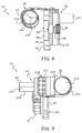
- FIG. 8 is a rear elevational view of the reflective dot sighting device in accordance with the present invention.
- FIG. 9 is a front elevational view thereof.
- FIG. 10 is a rear perspective view of a reflective dot sighting device in accordance with a further embodiment of the invention.
- a reflective sighting device 10 in accordance with the present invention is arranged to superimpose an illuminated dot 12 on a distant target 14 when a user (not shown) is in an aiming position.
- the dot 12 is in the same focal plane (or at the same focal distance) 16 as the target 14 .
- Slight movement of the sighting device, as represented by phantom lines 18 and 20 results in excessive movement of the dot 12 , as represented by dots 12 A and 12 B, over a relatively large distance D 2 .
- slight movement of the sighting device 10 may be almost imperceptible to the user, the resultant excessive movement of the dot 12 is readily noticed.
- the focal plane (or focal distance) 22 of a superimposed reflective dot 12 is preferably closer to the user than the focal plane (or focal distance) 16 of the target 14 .
- slight movement of the sight 10 results in less movement of the dot 12 , as represented by dots 12 C and 12 D, over a relatively small distance D 1 .
- the present invention facilitates the user's ability to steady the reflective dot 12 on a distant target during aiming to thereby increase shooting accuracy.
- the sighting device 10 is embodied as a bowsight.
- the sighting device 10 preferably includes a base member 32 with a bracket assembly 34 and a sight assembly 36 connected to the base member 32 .
- the bracket assembly 34 is useful for attaching the sight assembly to a bow (not shown) or the like.
- the sighting device 10 may be adapted for use with any projectile launching device such as a rifle, pellet gun, BB gun, pistol, paint marker, and the like, and can be used with other devices, such as telescopes, sighting scopes, and so on, in order to quickly align the device with a distal target or scene.
- any projectile launching device such as a rifle, pellet gun, BB gun, pistol, paint marker, and the like
- other devices such as telescopes, sighting scopes, and so on, in order to quickly align the device with a distal target or scene.
- the bracket assembly 34 includes a mounting bracket 38 that is preferably connected to the base member 32 via a first adjustment mechanism 40 for rotatably adjusting the vertical position of the sight assembly 36 .
- the sight assembly 36 is preferably connected to the base member 32 via a second adjustment mechanism 42 for adjusting both the lateral and vertical positions of the sight assembly 36 .
- vertical adjustment of the entire sight assembly 36 may be needed when initially calibrating the sighting device 10 with a particular bow or other device, when changing from one arrow type to another, when shooting from different heights, such as from the ground or a tree stand, and so on.
- the mounting bracket 38 preferably has a pair of vertically spaced openings 44 ( FIG. 3 ) for receiving fasteners (not shown) or the like to mount the sighting device 10 to a bow (not shown) in a conventional manner.
- a vertically extending guide slot 45 is formed at a rear section of the bracket 38 for a purpose to be described in greater detail below.
- the base member 32 preferably includes a first arcuate opening 46 concentric with a first pivot axis 48 of the first adjustment mechanism 40 and a second arcuate opening 50 concentric with a second pivot axis 52 of the second adjustment mechanism 42 .
- a first adjustment slot 54 extends rearwardly from the first arcuate opening 46 and intersects with a rear opening 56 ( FIG. 6 ) to thereby form a first pair of rearwardly extending clamping jaws 58 , 60 .
- a bolt 62 ( FIG. 4 ) extends through an opening 64 in the jaw 58 and into a threaded opening 66 ( FIG. 6 ) of the jaw 60 .
- rotation of the bolt 62 in a clockwise direction draws the jaws toward each other to clamp an adjustment disk 68 of the first adjustment mechanism 40 at a desired angular position while rotation of the bolt in a counter-clockwise direction causes the jaws to move away from each other for adjusting the position of the base member 32 with respect to the disk 68 .
- a second adjustment slot 70 extends forwardly from the second arcuate opening 50 and intersects with a front opening 72 ( FIG. 6 ) to thereby form a second pair of rearwardly extending clamping jaws 74 , 76 .
- a bolt 78 extends through an opening 80 in the jaw 58 and into a threaded opening 82 ( FIG. 6 ) of the jaw 76 .
- rotation of the bolt 78 in a clockwise direction draws the jaws 74 , 76 toward each other to clamp around a tubular adjustment member 83 of the second adjustment mechanism 42 at a desired position while rotation of the bolt in a counter-clockwise direction causes the jaws to move away from each other for adjusting the angular and linear position of the tubular adjustment member 83 with respect to the base member 32 .
- the first adjustment mechanism 40 also preferably includes a lever arm 84 connected to the adjustment disk 68 for rotation therewith.
- the lever arm 84 extends rearwardly from the adjustment disk 68 and terminates in an enlarged head 86 that can be manipulated by a user during adjustment.
- a pointer 88 ( FIG. 3 ) extends laterally from the head 86 and rides along a flat rearward surface 90 of the bracket 38 . Indicia (not shown) can be positioned along the surface 90 to inform the user of an adjustment position.
- a locking knob 92 is mounted to the lever arm 84 via a threaded fastener 94 that extends through both the lever arm 84 and the guide slot 45 .
- a head 96 of the fastener 94 is located within the guide slot such that rotation of the knob 92 in a clockwise direction locks the lever arm 84 , and thus the adjustment disk 68 , against movement. Likewise, loosening of the knob 92 in a counter-clockwise direction enables a user to adjust the position of the disk 68 , and thus the vertical position of the sight assembly 36 with respect to the bracket 38 .
- Indicia 98 can be located on the disk 68 while a corresponding pointer 100 can be located on the base member 32 in order to ascertain the adjustment position.
- the second adjustment mechanism 42 preferably includes the tubular adjustment member 83 with a base 102 ( FIG. 6 ), and a bolt 104 that extends through the base 102 of the tubular member and threads into the sight assembly 36 to thereby secure the sight assembly to the tubular member, and thus to the base member 32 when the jaws 74 , 76 are tightened around the tubular member 83 as previously described.
- a windage scale 106 ( FIG. 4 ) is preferably provided on the tubular member 83 for ascertaining lateral adjustment of the tubular member 83 , and thus a lateral position of the sight assembly 36 with respect to the base member 32 .
- indicia 108 is preferably located on the base member 32 and a corresponding line or indicator 110 ( FIG.
- the indicia 98 and indicia 108 begin and terminate at opposite ends of the scale so that the sight assembly can be leveled with greater facility with respect to a user.
- the lateral position of the sight assembly 36 it may be necessary to adjust the lateral position of the sight assembly 36 when used during windy conditions and/or when calibrating the sight device 10 .
- vertical and horizontal adjustment of the entire sight assembly 36 may be needed when initially calibrating the sighting device 10 with a particular bow (or other device) and arrow (or other projectile), when shooting from different distances and/or heights, such as from the ground or a tree stand, and so on.
- the user may wish to adjust the vertical height of the sight assembly 36 through manipulation of the first adjustment mechanism by loosening the knob 92 and applying force to the lever arm 84 to move the sight assembly upward or downward.
- Additional vertical adjustment is achieved by loosening the clamping jaws 58 , 60 by turning the screw 62 counter clockwise and rotating the base member 32 with respect to the disk 68 . Since vertical adjustment is caused by a rotating motion, the sight assembly may be oriented at an angle with respect to the bracket 38 to a position where the reflective dot cannot be viewed or is not properly positioned with respect to a user's line of sight. Accordingly, the second adjustment mechanism can be manipulated by loosening the clamping jaws 74 , 76 and rotating the tubular member 83 until the sight assembly 36 is oriented in the line of sight.
- the sight assembly 36 will be best understood with reference to a 3-axis coordinate system having a first axis 125 , a second axis 127 extending perpendicular to the first axis 125 , and a third axis 129 extending perpendicular to the first and second axes.
- the first axis 125 extends generally vertically while the second axes 127 and 129 extend in a generally horizontal plane.
- these terms are relative since the sight assembly 36 may be tilted at other orientations with respect to true vertical and horizontal coordinates during use, especially since different users may exhibit different aiming stances.
- the sight assembly 36 preferably includes an image generating portion 112 ( FIG. 6 ) and a reflective sight component 114 mounted within a tubular sight frame 116 .
- the reflective sight component has a reflective surface 115 and/or 117 that is adapted to face a user when in use.
- An adjustment knob 118 is connected to the sight frame 116 and is arranged to rotate clockwise or counterclockwise to adjust the luminous intensity of an image incident on the reflective sight component 114 to accommodate a user over a wide range of ambient light conditions.
- the knob 118 is preferably arranged to have detent positions so that discrete levels of luminous intensity can be selected.
- the knob can also be provided with an “off” position when the sighting device 10 is not in use. To that end, an alignment mark 120 ( FIG.
- knob 118 may be replaced with an ambient light sensor so that the luminous intensity can be automatically adjusted.
- a separate on/off switch may be provided either as a user manipulated device or as a tilt sensor or the like with an electronic timer for automatically turning on/off the sighting device.
- the image generating portion 112 preferably includes a light source 124 and a reticle 126 located adjacent to and in alignment with the light source.
- Light from the light source 124 is projected through the reticle 126 and onto the reflective sight component 114 , as represented by projection line 128 (shown in phantom line), which is in turn reflected toward the user along a user line of sight 130 (shown in phantom line), which is preferably coincident with a central axis of the tubular sight frame 116 and the third axis 129 of the 3-axis coordinate system.
- the projection line 128 is preferably located in a plane defined by the second axis 127 and third axis 129 so that the line of sight lies in the same plane as the light source 124 .
- the light source can be tilted upward or downward out of the plane.
- the particular image or sight pattern incident on the reflective sight component 114 as viewed by the user depends on the type of reticle used. Accordingly, it will be understood that the term “dot” as used herein refers not only to circular images but to cross-hairs, circles, triangles, and/or any other convenient shape for designating a distant target.
- the reflective sight component 114 is preferably in the form of a flat lens mounted in a forward end 141 of the sight frame 116 through well-known attachment means.
- the lens 114 preferably extends parallel to the first axis 125 and is oriented at a first angle a 1 with respect to the line of sight or the third axis 129 .
- the lens 114 is preferably constructed of a transparent material, such as glass, plastic or the like and includes a well-known reflective coating on one or both surfaces 115 , 117 so that the user can see both the reflected dot image from the light source 124 at one or more predetermined wavelengths and the distant scene or target through the lens 114 .
- the lens 114 is shown as a generally flat disk, it will be understood that it may be curved and/or used in conjunction with other coatings, lenses, and/or lens configurations to produce a particular visual effect and/or to reduce or prevent unwanted visual effects as is well known.
- the light source 124 is preferably in the form of a light emitting diode (LED) that emits radiant energy in the visible light region of the electromagnetic spectrum so that the resultant reflected image is visible to the naked eye.
- LED light emitting diode
- near infrared or other wavelengths may be used when accompanied by other viewing equipment, such as night vision devices.
- other light sources can be used, such as dual-color or tri-color LED's to give the user a selectable color choice for the reflected image, incandescent bulbs, laser diodes, fluorescent-doped fiber optics, tritium lights, combinations thereof, and so on.
- the light source 124 , reticle 126 and lens 114 are preferably arranged and oriented so that a perceived focal point of the reflected dot 12 is nearer to the user 134 than the focal point of the distant target, as shown in FIGS. 1 and 2 .
- the light source 124 is preferably located at a first distance L 1 from the lens 114 and at a second distance L 2 from a rear end 140 of the sight frame 116 (represented by phantom line in FIG. 7 ), where the distance L 1 is much smaller than the distance L 2 .
- the lens preferably extends parallel to or along the first axis 125 at a first acute angle a 1 with respect to the line of sight 130 (third axis 129 ) and at a second acute angle a 2 with respect to the projection line 128 of the light source 124 .
- the projection line 128 of the light source 124 extends at a third acute angle a 3 with respect to the line of sight 130 .
- the angles a 1 and a 2 are congruent and each is larger than the angle a 3 .
- the angles a 1 and a 2 are each preferably twice as large as angle a 3 .
- angles a 1 and a 2 are approximately 72 degrees and angle a 3 is approximately 36 degrees.
- angles a 1 , a 2 and a 3 can vary without departing from the spirit and scope of the invention.
- the focal plane of the dot 12 ( FIGS. 1 & 8 ) is closer than the focal plane of the target 14 .
- the focal plane of the dot 12 is at the lens. Accordingly, slight movement of the sight 10 and the bow or other device to which it is attached, results in less movement of the reflective dot over a relatively small distance when compared to the prior art.
- the present invention facilitates the user's ability to steady the reflective dot on a distant target during aiming to thereby increase shooting accuracy.
- the present invention also reduces the amount of time needed by the user to acquire the reflective dot in the field of view.
- the sighting dot can be positioned practically anywhere on the lens as viewed by the user without changing the accuracy of the shot since the focal plane of the dot is at the target.
- the focal plane of the dot 12 of the present invention is at or near the lens 114 , the dot 12 should be located consistently at the center of the lens (or consistently at another location on the lens) for better aiming accuracy.
- a rear sight 142 shown in broken line in FIG. 6 .
- the rear sight 142 is shown as a peep sight, it will be understood that other rear sights for bows and firearms can be used.
- At least one inner side wall 135 of the sight frame 116 is preferably covered with a non-reflective tape or coating to reduce unwanted reflections on the lens.
- the entire inner surface of the sight frame 116 can be constructed of or covered with or formed of one or more materials having non-reflective properties.
- a tubular insert 144 with non-reflective properties is installed in the sight frame 116 to reduce unwanted reflections on the lens.
- the insert 144 can be permanently installed or removable for accommodating various ambient light conditions.
Landscapes
- Physics & Mathematics (AREA)
- Optics & Photonics (AREA)
- Engineering & Computer Science (AREA)
- General Engineering & Computer Science (AREA)
- Telescopes (AREA)
Abstract
Description
Claims (23)
Priority Applications (1)
| Application Number | Priority Date | Filing Date | Title |
|---|---|---|---|
| US12/570,507 US8879146B2 (en) | 2008-09-30 | 2009-09-30 | Reflective dot sighting device with perceived dot location |
Applications Claiming Priority (2)
| Application Number | Priority Date | Filing Date | Title |
|---|---|---|---|
| US10125808P | 2008-09-30 | 2008-09-30 | |
| US12/570,507 US8879146B2 (en) | 2008-09-30 | 2009-09-30 | Reflective dot sighting device with perceived dot location |
Publications (2)
| Publication Number | Publication Date |
|---|---|
| US20100077645A1 US20100077645A1 (en) | 2010-04-01 |
| US8879146B2 true US8879146B2 (en) | 2014-11-04 |
Family
ID=42055888
Family Applications (1)
| Application Number | Title | Priority Date | Filing Date |
|---|---|---|---|
| US12/570,507 Active 2033-05-26 US8879146B2 (en) | 2008-09-30 | 2009-09-30 | Reflective dot sighting device with perceived dot location |
Country Status (1)
| Country | Link |
|---|---|
| US (1) | US8879146B2 (en) |
Cited By (12)
| Publication number | Priority date | Publication date | Assignee | Title |
|---|---|---|---|---|
| US9479934B2 (en) | 2013-12-13 | 2016-10-25 | Parallel Wireless, Inc. | Virtualization of the evolved packet core to create a local EPC |
| US9500442B2 (en) | 2013-07-15 | 2016-11-22 | OptiFlow, Inc. | Holographic gun sight |
| US9910259B2 (en) | 2013-07-09 | 2018-03-06 | Corey Zieger | Modular holographic sighting system |
| US10247515B2 (en) | 2015-06-26 | 2019-04-02 | Ziel Optics, Inc. | Holographic sight with optimized reflection and image angles |
| US10254532B2 (en) | 2015-06-26 | 2019-04-09 | Ziel Optics, Inc. | Hybrid holographic sight |
| US11243048B1 (en) | 2018-10-24 | 2022-02-08 | Kraig Bryan | Firearm sight |
| US11566870B1 (en) | 2021-07-31 | 2023-01-31 | ARES Archery Ltd. | Bow aim signal converter |
| US11740053B2 (en) | 2020-08-03 | 2023-08-29 | Sturm, Ruger & Company, Inc. | Integrated optical sighting system for firearm |
| US11976901B2 (en) | 2021-06-07 | 2024-05-07 | Sturm, Ruger & Company, Inc. | Passively illuminated fiber optic reflex sights for firearms |
| USD1066553S1 (en) | 2022-01-07 | 2025-03-11 | Crimson Trace Corporation | Weapon sight |
| US12298101B2 (en) | 2021-11-07 | 2025-05-13 | Crimson Trace Corporation | Weapon sight grip |
| US12571610B2 (en) | 2021-06-07 | 2026-03-10 | Sturm, Ruger & Company, Inc. | Optical sight for firearm with integral rear sight |
Families Citing this family (7)
| Publication number | Priority date | Publication date | Assignee | Title |
|---|---|---|---|---|
| CN102155866B (en) * | 2011-01-14 | 2013-06-12 | 北京理工大学 | Method for elliminating baseline drift of sight line |
| US9869527B2 (en) * | 2014-12-13 | 2018-01-16 | Precision Accuracy Solutions, Inc. | Supplementary sight aid adaptable to existing and new sight aid |
| US10837737B1 (en) * | 2016-08-02 | 2020-11-17 | Jimmie L. Wright | LED illuminating weapon sighting system |
| US11287220B2 (en) * | 2019-02-15 | 2022-03-29 | Grace Engineering Corp. | Macro alignment reticle sight system |
| US11761816B2 (en) | 2021-12-08 | 2023-09-19 | Trijicon, Inc. | Reflex sight |
| US11796284B2 (en) * | 2021-12-08 | 2023-10-24 | Trijicon, Inc. | Reflex sight |
| US11614225B1 (en) | 2021-12-08 | 2023-03-28 | Trijicon, Inc. | Reflex sight |
Citations (16)
| Publication number | Priority date | Publication date | Assignee | Title |
|---|---|---|---|---|
| US2780130A (en) | 1954-01-29 | 1957-02-05 | Eastman Kodak Co | Reflex sight having a dichroic beamcombining mirror |
| US3942901A (en) * | 1973-03-26 | 1976-03-09 | John Arne Ingemund Ekstrand | Optical sighting instrument with means for producing a sighting mark |
| US4346995A (en) | 1980-07-14 | 1982-08-31 | Morris Donald D | Off axis optical sight system for a firearm |
| US4658139A (en) * | 1985-02-04 | 1987-04-14 | Baird Corporation | Night vision reflex sight |
| US5090805A (en) | 1990-08-15 | 1992-02-25 | Blount, Inc. | Bow sight with projected reticle aiming spot |
| US5205044A (en) | 1991-11-12 | 1993-04-27 | Depaoli Alfred C | Luminous dot sighting instrument |
| US5383278A (en) | 1993-01-13 | 1995-01-24 | Kay; Ira M. | Wide field of view reflex sight for a bow |
| US5653034A (en) | 1995-05-24 | 1997-08-05 | Trijicon, Inc. | Reflex sighting device for day and night sighting |
| US6807742B2 (en) | 2002-09-06 | 2004-10-26 | Trijicon, Inc. | Reflex sight with multiple power sources for reticle |
| US20050091900A1 (en) * | 1999-06-14 | 2005-05-05 | Tippmann Dennis J.Jr. | Gun |
| US6967775B1 (en) * | 2004-07-13 | 2005-11-22 | Millett Industries, Inc. | Zoom dot sighting system |
| US7234265B1 (en) * | 2005-12-07 | 2007-06-26 | Li-Der Cheng | Internal red dot sight |
| US20070180751A1 (en) * | 2006-02-08 | 2007-08-09 | Joannes Rene | "Moving red dot" sighting device |
| US20090139100A1 (en) * | 2007-06-18 | 2009-06-04 | Kingsbury Klint M | Multi-spot adjustable reflex bow sight |
| US20090193705A1 (en) * | 2008-02-06 | 2009-08-06 | Truglo, Inc. | Sighting Device with Trajectory Compensation |
| US7574810B1 (en) * | 2006-07-18 | 2009-08-18 | Truglo, Inc. | Illuminated reflective sighting device |
-
2009
- 2009-09-30 US US12/570,507 patent/US8879146B2/en active Active
Patent Citations (18)
| Publication number | Priority date | Publication date | Assignee | Title |
|---|---|---|---|---|
| US2780130A (en) | 1954-01-29 | 1957-02-05 | Eastman Kodak Co | Reflex sight having a dichroic beamcombining mirror |
| US3942901A (en) * | 1973-03-26 | 1976-03-09 | John Arne Ingemund Ekstrand | Optical sighting instrument with means for producing a sighting mark |
| US4346995A (en) | 1980-07-14 | 1982-08-31 | Morris Donald D | Off axis optical sight system for a firearm |
| US4658139A (en) * | 1985-02-04 | 1987-04-14 | Baird Corporation | Night vision reflex sight |
| US5090805A (en) | 1990-08-15 | 1992-02-25 | Blount, Inc. | Bow sight with projected reticle aiming spot |
| US5205044A (en) | 1991-11-12 | 1993-04-27 | Depaoli Alfred C | Luminous dot sighting instrument |
| US5813159A (en) * | 1993-01-13 | 1998-09-29 | Kay; Ira Mark | Wide field of view reflex gunsight |
| US5383278A (en) | 1993-01-13 | 1995-01-24 | Kay; Ira M. | Wide field of view reflex sight for a bow |
| US5653034A (en) | 1995-05-24 | 1997-08-05 | Trijicon, Inc. | Reflex sighting device for day and night sighting |
| US20050091900A1 (en) * | 1999-06-14 | 2005-05-05 | Tippmann Dennis J.Jr. | Gun |
| US6807742B2 (en) | 2002-09-06 | 2004-10-26 | Trijicon, Inc. | Reflex sight with multiple power sources for reticle |
| US6967775B1 (en) * | 2004-07-13 | 2005-11-22 | Millett Industries, Inc. | Zoom dot sighting system |
| US7234265B1 (en) * | 2005-12-07 | 2007-06-26 | Li-Der Cheng | Internal red dot sight |
| US20070180751A1 (en) * | 2006-02-08 | 2007-08-09 | Joannes Rene | "Moving red dot" sighting device |
| US7574810B1 (en) * | 2006-07-18 | 2009-08-18 | Truglo, Inc. | Illuminated reflective sighting device |
| US20090139100A1 (en) * | 2007-06-18 | 2009-06-04 | Kingsbury Klint M | Multi-spot adjustable reflex bow sight |
| US7814669B2 (en) * | 2007-06-18 | 2010-10-19 | Kingsbury Klint M | Multi-spot adjustable reflex bow sight |
| US20090193705A1 (en) * | 2008-02-06 | 2009-08-06 | Truglo, Inc. | Sighting Device with Trajectory Compensation |
Cited By (13)
| Publication number | Priority date | Publication date | Assignee | Title |
|---|---|---|---|---|
| US9910259B2 (en) | 2013-07-09 | 2018-03-06 | Corey Zieger | Modular holographic sighting system |
| US9500442B2 (en) | 2013-07-15 | 2016-11-22 | OptiFlow, Inc. | Holographic gun sight |
| US9752852B2 (en) | 2013-07-15 | 2017-09-05 | Ziel Optics, Inc. | Gun sight |
| US9479934B2 (en) | 2013-12-13 | 2016-10-25 | Parallel Wireless, Inc. | Virtualization of the evolved packet core to create a local EPC |
| US10247515B2 (en) | 2015-06-26 | 2019-04-02 | Ziel Optics, Inc. | Holographic sight with optimized reflection and image angles |
| US10254532B2 (en) | 2015-06-26 | 2019-04-09 | Ziel Optics, Inc. | Hybrid holographic sight |
| US11243048B1 (en) | 2018-10-24 | 2022-02-08 | Kraig Bryan | Firearm sight |
| US11740053B2 (en) | 2020-08-03 | 2023-08-29 | Sturm, Ruger & Company, Inc. | Integrated optical sighting system for firearm |
| US11976901B2 (en) | 2021-06-07 | 2024-05-07 | Sturm, Ruger & Company, Inc. | Passively illuminated fiber optic reflex sights for firearms |
| US12571610B2 (en) | 2021-06-07 | 2026-03-10 | Sturm, Ruger & Company, Inc. | Optical sight for firearm with integral rear sight |
| US11566870B1 (en) | 2021-07-31 | 2023-01-31 | ARES Archery Ltd. | Bow aim signal converter |
| US12298101B2 (en) | 2021-11-07 | 2025-05-13 | Crimson Trace Corporation | Weapon sight grip |
| USD1066553S1 (en) | 2022-01-07 | 2025-03-11 | Crimson Trace Corporation | Weapon sight |
Also Published As
| Publication number | Publication date |
|---|---|
| US20100077645A1 (en) | 2010-04-01 |
Similar Documents
| Publication | Publication Date | Title |
|---|---|---|
| US8879146B2 (en) | Reflective dot sighting device with perceived dot location | |
| US7574810B1 (en) | Illuminated reflective sighting device | |
| US20090193705A1 (en) | Sighting Device with Trajectory Compensation | |
| US12031796B2 (en) | Optical system with cant indication | |
| US7552558B1 (en) | Mirror sight apparatus with integral rear sight | |
| US9285188B1 (en) | Adjustable sighting device for archery | |
| US9759520B2 (en) | Method and system for aligning a point of aim with a point of impact for a projectile device | |
| US8919027B2 (en) | Firearm and air gun sight | |
| US7685760B1 (en) | Paintball marker sight apparatus | |
| US7937879B2 (en) | Rifle scope with a low-light visible element | |
| CA2324685C (en) | Rifle scope with side indicia | |
| US6604315B1 (en) | Method and apparatus for maintaining proper orientation of aiming eye when firing shotgun | |
| US8619238B2 (en) | Rangefinder for shooting device and method of aligning rangefinder to shooting device sight | |
| US20070130817A1 (en) | Mirror sight apparatus with position locking mechanism | |
| US10488156B2 (en) | Optical system accessory with cant indication | |
| US8752303B2 (en) | Sighting system | |
| US20150040409A1 (en) | Bow sight apparatus having multiple lasers | |
| US8069577B1 (en) | Optical sight device | |
| US6098608A (en) | Backsight assembly for hunting bow | |
| US9915502B2 (en) | Backlit sighting device | |
| US4695159A (en) | Improvements in sights for firearms and other articles | |
| US9644921B1 (en) | Sight assembly with illuminated sight point | |
| US5784182A (en) | Directional sight for instruments | |
| US5255440A (en) | Archery alignment method | |
| CN112236641A (en) | Reticle with Fiber Optic Illumination |
Legal Events
| Date | Code | Title | Description |
|---|---|---|---|
| AS | Assignment |
Owner name: TRUGLO, INC.,TEXAS Free format text: ASSIGNMENT OF ASSIGNORS INTEREST;ASSIGNOR:LOROCCO, PAUL;REEL/FRAME:023439/0968 Effective date: 20090930 Owner name: TRUGLO, INC., TEXAS Free format text: ASSIGNMENT OF ASSIGNORS INTEREST;ASSIGNOR:LOROCCO, PAUL;REEL/FRAME:023439/0968 Effective date: 20090930 |
|
| AS | Assignment |
Owner name: TRUGLO, INC., TEXAS Free format text: ASSIGNMENT OF ASSIGNORS INTEREST;ASSIGNORS:LOROCCO, PAUL;ESTRIDGE, JOHN;REEL/FRAME:032598/0970 Effective date: 20140402 |
|
| STCF | Information on status: patent grant |
Free format text: PATENTED CASE |
|
| FEPP | Fee payment procedure |
Free format text: MAINTENANCE FEE REMINDER MAILED (ORIGINAL EVENT CODE: REM.) |
|
| FEPP | Fee payment procedure |
Free format text: SURCHARGE FOR LATE PAYMENT, SMALL ENTITY (ORIGINAL EVENT CODE: M2554); ENTITY STATUS OF PATENT OWNER: SMALL ENTITY |
|
| MAFP | Maintenance fee payment |
Free format text: PAYMENT OF MAINTENANCE FEE, 4TH YR, SMALL ENTITY (ORIGINAL EVENT CODE: M2551); ENTITY STATUS OF PATENT OWNER: SMALL ENTITY Year of fee payment: 4 |
|
| AS | Assignment |
Owner name: TRU-GLO, INC., TEXAS Free format text: CORRECT PATENTEE NAME;ASSIGNOR:TRUGLO, INC.;REEL/FRAME:055093/0724 Effective date: 19931122 |
|
| AS | Assignment |
Owner name: GOOD SPORTSMAN MARKETING, L.L.C., TEXAS Free format text: ASSIGNMENT OF ASSIGNORS INTEREST;ASSIGNOR:TRU-GLO, INC.;REEL/FRAME:055138/0179 Effective date: 20210203 |
|
| AS | Assignment |
Owner name: TRU-GLO, INC., TEXAS Free format text: CORRECTIVE ASSIGNMENT TO CORRECT THE DOCUMENT DATE PREVIOUSLY RECORDED ON REEL 055093 FRAME 0724. ASSIGNOR(S) HEREBY CONFIRMS THE EXECUTION DATE;ASSIGNOR:TRUGLO, INC.;REEL/FRAME:055233/0406 Effective date: 20210125 |
|
| AS | Assignment |
Owner name: NXT CAPITAL, LLC, AS AGENT, ILLINOIS Free format text: SECURITY INTEREST;ASSIGNOR:GOOD SPORTSMAN MARKETING, L.L.C.;REEL/FRAME:056833/0345 Effective date: 20210713 |
|
| MAFP | Maintenance fee payment |
Free format text: PAYMENT OF MAINTENANCE FEE, 8TH YR, SMALL ENTITY (ORIGINAL EVENT CODE: M2552); ENTITY STATUS OF PATENT OWNER: SMALL ENTITY Year of fee payment: 8 |
|
| AS | Assignment |
Owner name: BANK OF AMERICA, N.A., AS COLLATERAL AGENT, CALIFORNIA Free format text: SECURITY AGREEMENT (ABL);ASSIGNOR:GOOD SPORTSMAN MARKETING, L.L.C.;REEL/FRAME:069084/0029 Effective date: 20240930 Owner name: BANK OF AMERICA, N.A., AS COLLATERAL AGENT, NORTH CAROLINA Free format text: SECURITY AGREEMENT (2L TERM LOAN);ASSIGNOR:GOOD SPORTSMAN MARKETING, L.L.C.;REEL/FRAME:069083/0397 Effective date: 20240930 Owner name: BANK OF AMERICA, N.A., AS COLLATERAL AGENT, NORTH CAROLINA Free format text: SECURITY AGREEMENT (1L TERM LOAN);ASSIGNOR:GOOD SPORTSMAN MARKETING, L.L.C.;REEL/FRAME:069083/0371 Effective date: 20240930 |
|
| AS | Assignment |
Owner name: GOOD SPORTSMAN MARKETING, L.L.C., TEXAS Free format text: RELEASE BY SECURED PARTY;ASSIGNOR:ALTER DOMUS (US) LLC, AS AGENT;REEL/FRAME:069174/0614 Effective date: 20240930 Owner name: WGI INNOVATIONS, LTD., TEXAS Free format text: RELEASE BY SECURED PARTY;ASSIGNOR:NXT CAPITAL, LLC, AS AGENT;REEL/FRAME:069113/0431 Effective date: 20240930 Owner name: BARNETT OUTDOORS, LLC, TEXAS Free format text: RELEASE BY SECURED PARTY;ASSIGNOR:NXT CAPITAL, LLC, AS AGENT;REEL/FRAME:069113/0431 Effective date: 20240930 Owner name: WILDGAME INNOVATIONS, L.L.C., TEXAS Free format text: RELEASE BY SECURED PARTY;ASSIGNOR:NXT CAPITAL, LLC, AS AGENT;REEL/FRAME:069113/0431 Effective date: 20240930 Owner name: EVOLVED INGENUITY, LLC, TEXAS Free format text: RELEASE BY SECURED PARTY;ASSIGNOR:NXT CAPITAL, LLC, AS AGENT;REEL/FRAME:069113/0431 Effective date: 20240930 Owner name: GOOD SPORTSMAN MARKETING, L.L.C., TEXAS Free format text: RELEASE BY SECURED PARTY;ASSIGNOR:NXT CAPITAL, LLC, AS AGENT;REEL/FRAME:069113/0431 Effective date: 20240930 |