US8875867B2 - Bottle feeding and processing system - Google Patents
Bottle feeding and processing system Download PDFInfo
- Publication number
- US8875867B2 US8875867B2 US13/634,431 US201113634431A US8875867B2 US 8875867 B2 US8875867 B2 US 8875867B2 US 201113634431 A US201113634431 A US 201113634431A US 8875867 B2 US8875867 B2 US 8875867B2
- Authority
- US
- United States
- Prior art keywords
- bottles
- speed
- movement
- centrifuge
- rotation
- Prior art date
- Legal status (The legal status is an assumption and is not a legal conclusion. Google has not performed a legal analysis and makes no representation as to the accuracy of the status listed.)
- Expired - Fee Related, expires
Links
- 230000004807 localization Effects 0.000 claims description 12
- 238000006073 displacement reaction Methods 0.000 claims description 10
- 238000000605 extraction Methods 0.000 claims description 7
- 238000004519 manufacturing process Methods 0.000 claims description 7
- 230000015654 memory Effects 0.000 claims description 7
- 238000011144 upstream manufacturing Methods 0.000 claims description 5
- 230000007246 mechanism Effects 0.000 claims description 4
- 230000001360 synchronised effect Effects 0.000 claims description 4
- 238000011084 recovery Methods 0.000 claims description 3
- 102220049647 rs184898622 Human genes 0.000 claims description 3
- 102220008426 rs394105 Human genes 0.000 claims description 3
- 230000008021 deposition Effects 0.000 claims description 2
- 238000000034 method Methods 0.000 claims description 2
- 102220006727 rs113994181 Human genes 0.000 claims description 2
- 238000001514 detection method Methods 0.000 claims 3
- 238000000151 deposition Methods 0.000 description 5
- 230000006870 function Effects 0.000 description 5
- 230000008901 benefit Effects 0.000 description 3
- 230000001788 irregular Effects 0.000 description 3
- 230000001419 dependent effect Effects 0.000 description 2
- 239000000463 material Substances 0.000 description 2
- 230000009467 reduction Effects 0.000 description 2
- 244000027321 Lychnis chalcedonica Species 0.000 description 1
- 238000009825 accumulation Methods 0.000 description 1
- 230000009471 action Effects 0.000 description 1
- 230000004913 activation Effects 0.000 description 1
- 230000008859 change Effects 0.000 description 1
- 230000001143 conditioned effect Effects 0.000 description 1
- 230000009849 deactivation Effects 0.000 description 1
- 238000010586 diagram Methods 0.000 description 1
- 230000000694 effects Effects 0.000 description 1
- 239000000284 extract Substances 0.000 description 1
- 238000010348 incorporation Methods 0.000 description 1
- 238000009434 installation Methods 0.000 description 1
- 230000002452 interceptive effect Effects 0.000 description 1
- 238000002372 labelling Methods 0.000 description 1
- 230000007257 malfunction Effects 0.000 description 1
- 230000001105 regulatory effect Effects 0.000 description 1
- 230000008672 reprogramming Effects 0.000 description 1
- 230000000717 retained effect Effects 0.000 description 1
- 238000007789 sealing Methods 0.000 description 1
Images


Classifications
-
- B—PERFORMING OPERATIONS; TRANSPORTING
- B65—CONVEYING; PACKING; STORING; HANDLING THIN OR FILAMENTARY MATERIAL
- B65B—MACHINES, APPARATUS OR DEVICES FOR, OR METHODS OF, PACKAGING ARTICLES OR MATERIALS; UNPACKING
- B65B37/00—Supplying or feeding fluent-solid, plastic, or liquid material, or loose masses of small articles, to be packaged
-
- B—PERFORMING OPERATIONS; TRANSPORTING
- B65—CONVEYING; PACKING; STORING; HANDLING THIN OR FILAMENTARY MATERIAL
- B65G—TRANSPORT OR STORAGE DEVICES, e.g. CONVEYORS FOR LOADING OR TIPPING, SHOP CONVEYOR SYSTEMS OR PNEUMATIC TUBE CONVEYORS
- B65G47/00—Article or material-handling devices associated with conveyors; Methods employing such devices
- B65G47/02—Devices for feeding articles or materials to conveyors
- B65G47/04—Devices for feeding articles or materials to conveyors for feeding articles
- B65G47/12—Devices for feeding articles or materials to conveyors for feeding articles from disorderly-arranged article piles or from loose assemblages of articles
- B65G47/14—Devices for feeding articles or materials to conveyors for feeding articles from disorderly-arranged article piles or from loose assemblages of articles arranging or orientating the articles by mechanical or pneumatic means during feeding
- B65G47/1407—Devices for feeding articles or materials to conveyors for feeding articles from disorderly-arranged article piles or from loose assemblages of articles arranging or orientating the articles by mechanical or pneumatic means during feeding the articles being fed from a container, e.g. a bowl
- B65G47/1442—Devices for feeding articles or materials to conveyors for feeding articles from disorderly-arranged article piles or from loose assemblages of articles arranging or orientating the articles by mechanical or pneumatic means during feeding the articles being fed from a container, e.g. a bowl by means of movement of the bottom or a part of the wall of the container
- B65G47/1457—Rotating movement in the plane of the rotating part
-
- B—PERFORMING OPERATIONS; TRANSPORTING
- B65—CONVEYING; PACKING; STORING; HANDLING THIN OR FILAMENTARY MATERIAL
- B65G—TRANSPORT OR STORAGE DEVICES, e.g. CONVEYORS FOR LOADING OR TIPPING, SHOP CONVEYOR SYSTEMS OR PNEUMATIC TUBE CONVEYORS
- B65G47/00—Article or material-handling devices associated with conveyors; Methods employing such devices
- B65G47/22—Devices influencing the relative position or the attitude of articles during transit by conveyors
- B65G47/24—Devices influencing the relative position or the attitude of articles during transit by conveyors orientating the articles
-
- B—PERFORMING OPERATIONS; TRANSPORTING
- B65—CONVEYING; PACKING; STORING; HANDLING THIN OR FILAMENTARY MATERIAL
- B65G—TRANSPORT OR STORAGE DEVICES, e.g. CONVEYORS FOR LOADING OR TIPPING, SHOP CONVEYOR SYSTEMS OR PNEUMATIC TUBE CONVEYORS
- B65G2201/00—Indexing codes relating to handling devices, e.g. conveyors, characterised by the type of product or load being conveyed or handled
- B65G2201/02—Articles
- B65G2201/0235—Containers
- B65G2201/0244—Bottles
-
- B—PERFORMING OPERATIONS; TRANSPORTING
- B65—CONVEYING; PACKING; STORING; HANDLING THIN OR FILAMENTARY MATERIAL
- B65G—TRANSPORT OR STORAGE DEVICES, e.g. CONVEYORS FOR LOADING OR TIPPING, SHOP CONVEYOR SYSTEMS OR PNEUMATIC TUBE CONVEYORS
- B65G2203/00—Indexing code relating to control or detection of the articles or the load carriers during conveying
- B65G2203/04—Detection means
- B65G2203/041—Camera
-
- B—PERFORMING OPERATIONS; TRANSPORTING
- B65—CONVEYING; PACKING; STORING; HANDLING THIN OR FILAMENTARY MATERIAL
- B65G—TRANSPORT OR STORAGE DEVICES, e.g. CONVEYORS FOR LOADING OR TIPPING, SHOP CONVEYOR SYSTEMS OR PNEUMATIC TUBE CONVEYORS
- B65G47/00—Article or material-handling devices associated with conveyors; Methods employing such devices
- B65G47/22—Devices influencing the relative position or the attitude of articles during transit by conveyors
- B65G47/26—Devices influencing the relative position or the attitude of articles during transit by conveyors arranging the articles, e.g. varying spacing between individual articles
- B65G47/30—Devices influencing the relative position or the attitude of articles during transit by conveyors arranging the articles, e.g. varying spacing between individual articles during transit by a series of conveyors
- B65G47/31—Devices influencing the relative position or the attitude of articles during transit by conveyors arranging the articles, e.g. varying spacing between individual articles during transit by a series of conveyors by varying the relative speeds of the conveyors forming the series
Definitions
- the present invention relates to a bottle feeding and processing system for feeding suitably oriented bottles to machines for filling said bottles.
- feed apparatus have been developed such that bottles, initially arranged randomly in special containers, can be fed to said filling machines with said bottles arranged in an ordered sequence.
- the receiving containers move with a rotational movement about a vertical axis and, inside them, the bottles are moved by means of the centrifugal force and frictional phenomena towards tangential shaped selectors (also known as pockets) which are provided on the side surface of the receiving container and in a lower position with respect to the bottom of said container.
- tangential shaped selectors also known as pockets
- An extraction device which is arranged in a suitable position on the circumference of the cylindrical container and below it, extracts the bottles from the shaped selectors, being displaced so as to allow each bottle to fall in an erect position into a seat, for example of a Maltese cross device, suitable for transporting the extracted bottles.
- the selectors may comprise adjustable retaining blades which may be associated with servomotors so as to be able to moved and adapted to the specific bottles to be extracted.
- the queuing station must have a considerable length, which is often incompatible with the spaces available in the premises for installation of the entire plant;
- the plant In order to solve this problem for those bottles which are difficult to keep in an erect position, the plant must also be provided with a machine which is arranged along the path towards the queuing station and which deposits the bottles into support cups which travel on the belt of the queuing station, transporting the bottles and preventing them from overturning.
- the technical problem which is posed therefore is to provide a bottle feeding and processing system for feeding the bottles to filling machine entry devices, which is able to provide a solution to the prior art problems described above, ensuring an optimum feeding efficiency, a reduction in the machine downtime due to the need for format change-over when there is a variation in the form of the bottles, and small overall dimensions.
- FIG. 1 shows a perspective view of the feeding and processing system according to the invention
- FIG. 2 shows a side view of the system according to FIG. 1 ;
- FIG. 3 shows a view, from above, of the system according to FIG. 2 ;
- FIG. 4 shows a perspective view of the realignment centrifuge
- FIG. 5 shows a cross-section along a diametral vertical plane of the centrifuge according to FIG. 4 ;
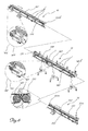
- FIG. 6 shows a perspective view of the devices for moving the bottles leaving the centrifuge
- FIG. 7 shows a perspective view of the device for orienting the bottles according to FIG. 5 ;
- FIG. 8 shows a perspective view of a first embodiment of an orientation machine comprising three orientation devices
- FIG. 9 shows a block diagram of the programming and control unit associated with the system
- FIG. 10 show schematic views of the working sequence of a second embodiment of an orientation machine with the bottle fed with its mouth directed downstream;
- FIG. 11 show schematic views of the working sequence of the orientation machine according to FIG. 10 with the bottled fed with its mouth directed upstream.
- a system for feeding and processing bottles 1 which have a mouth 1 a and a base 1 b and are arranged randomly in a store at the start of the line, comprises a feed station with a feed apparatus 10 which feeds bottles 1 to a station 20 for processing/handling bottles 1 , which orients the bottles correctly, depositing them on devices 30 , normally in the form of a screw feeder, for entry into the filling machine 40 which operates at
- the container 111 has a cylindrical shape and that the bottles 1 are fed, for example, by means of raising devices 112 which are associated with an inlet channel in the form of a hopper 112 a and which are conventional per se and therefore only schematically shown in FIG. 1 .
- the centrifuge 100 also comprises ( FIGS. 4 and 5 ) a containing bowl 117 and a drive system 118 ( FIG. 4 ) designed to move the various parts of the centrifuge so that rotation of the bowl 117 and a disc-shaped element 119 situated inside it produces a movement of the bottles 1 such as cause them to move back up towards the annular edge 122 against which they are forced in the vertical direction by means of interference with the section of a circular rim 124 , thus being arranged horizontally, i.e. with their axis corresponding to the large dimension parallel to the plane of the longitudinal axis of the apparatus, being arranged aligned on the edge 122 and substantially in contact with each other, albeit with a random mouth 1 a /base 1 b orientation.
- the rotation of the bowl 117 and the disc-shaped element 119 keeps the bottles 1 , aligned on the edge 122 , pushed towards the outlet mouth 113 from where they exit, in the horizontal position, in a continuous line without gaps due to a missing bottle, said gaps being prevented by the particular structure of the centrifuge which, feeding the containers in the horizontal position, is not conditioned by the correct entry of the bottles into vertical pockets as occurs in the prior art.
- the speed of rotation of the bowl 117 and the disc-shaped element 119 also determines the speed of the centrifuge 100 in terms of bottles exiting per unit of time, said speed being dependent on and related to the operating speed Vp of the filling machine 40 arranged downstream and in series with the devices for handling and conveying the bottles towards the said filling station.
- Vp the production speed of the line
- Vc the speed of rotation of the centrifuge expressed in meters/minute
- the feed station envisages that, downstream of the centrifuge 100 , devices are arranged for moving the bottles 1 in a horizontal position from the outlet mouth 113 of the said centrifuge 100 ; in detail said devices for moving the bottles 1 comprise:
- the first movement device 12 comprises a conveyor belt 130 , called an “accumulation belt”, made of material with a low coefficient of friction so that each bottle is able to travel on the belt pushed by the next bottle and vary its relative position with respect to the bottle in front of it, so as to allow recovery of any relative spaces formed between bottles and ensure that a succession of containers exit at the downstream end 130 b of the belt all in the horizontal position and always in contact with each other.
- a conveyor belt 130 called an “accumulation belt”
- accumulation belt made of material with a low coefficient of friction so that each bottle is able to travel on the belt pushed by the next bottle and vary its relative position with respect to the bottle in front of it, so as to allow recovery of any relative spaces formed between bottles and ensure that a succession of containers exit at the downstream end 130 b of the belt all in the horizontal position and always in contact with each other.
- this second movement device 13 comprises a conveyor belt 140 , called a “synchronization belt”, made of material with a high coefficient of friction. The high degree of friction ensures that any disturbances affecting the centrifuge (knocks or jolts due to transients during feeding) do not cause the chain of bottles to slide forwards in an uncontrolled manner.
- This belt 150 moves at a speed V 14 greater than the speed V 13 of the second belt 140 and synchronized with that of the bottle allocation screw feeder, depending on the speed Vp of the filling machine, so as to introduce a predefined relative spacing in the longitudinal direction of advancing movement of the bottles when they pass from the second belt to the third belt.
- a fixed base-piece 143 is arranged between the second conveyor belt 140 and the third conveyor belt 150 at the respective facing output/input ends 140 b , 150 a thereof.
- the fixed base-piece 143 forms a stable connection between the second belt 140 and the third belt 150 , ensuring safe passage of the bottles 1 from the second belt to the third belt and preventing any risk of sliding or falling from the production line.
- the conveying devices 12 , 13 , 12 comprise a pair of shoulders 132 , 133 arranged on the two longitudinal sides of the said conveyor belts and displaceable relative to each other in the transverse direction Y-Y with respect to the transverse dimension of the bottles 1 in transit.
- these shoulders 132 , 133 ensure that alignment of the bottles 1 from the centrifuge 100 is maintained, therefore keeping these bottles in a position ideal for subsequent handling in order to perform orientation thereof.
- said shoulders are connected to a regulating handwheel 132 a able to operate a mechanism 132 b for example of the rack and pinion type connected to at least one of the two shoulders so as to displace mechanically at least one of the two shoulders 132 , 133 relative to each other.
- means 600 for detecting the orientation of the horizontally lying bottle 1 are arranged along the path of the third conveyor device 14 ; these means 600 may, for example, comprise a telecamera which is arranged above the third belt 150 and which, directed at the bottle 1 , detects whether its mouth 1 a is arranged downstream or upstream in the direction of advancing movement X-X, generating a corresponding different signal for each case.
- the telecamera 600 may also detect:
- All the signals emitted by the telecamera 600 are sent to a control unit 500 , described below, associated with the system; said unit can then send this signal to the processing/handling station 20 arranged downstream of the feed apparatus so that said station can correctly handle the bottle so that it is always made to assume the same condition with the mouth open upwards whatever the position in which it arrives at the said station 20 .
- the station 20 for processing/handling the bottles 1 is located downstream of the feed station 10 , said station 20 , after picking up the bottles from the third conveyor belt 150 , correctly orienting them and depositing them inside a respective seat of the screw feeder 30 for entry into the filling machine 40 .
- the processing station 20 in turn comprises an orientation device 21 ( FIG. 7 ) for orienting the bottles 1 leaving said orientation station, which comprises:
- the gripping means 5 consist of a suction cup, which may be associated with suction means and which offers the advantage of being able to adhere to surfaces which are perfectly flat, for example with a concave or convex curvature and in some cases with an irregular shape, such as those typical of the bottles 1 .
- the orientation device 21 comprises a third actuator 4 designed to rotate the bottle 1 , in both the clockwise and anti-clockwise directions, about a third axis of rotation III parallel to the vertical direction Z-Z ( FIG. 7 ), namely perpendicular to the second axis of rotation and to the first axis of rotation.
- the third actuator 4 is designed to rotate the bottle 1 about its longitudinal axis, after being positioned in an erect position by the second actuator 3 .
- the third axis of rotation III coincides with the longitudinal axis of the bottle 1 .
- the third actuator 4 is provided with gripping means 41 for gripping the bottle 1 . Gripping is performed around the inlet mouth of the bottle 1 .
- a gripper such as the gripping means 41 is particularly convenient for the bottles 1 , being particularly suitable for gripping a bottle around a neck portion.
- the processing station 20 also comprises means 25 for supporting the devices 21 , said support means 25 being such as to maintain the possibility of rotation of each actuator about its axes of rotation and perform translatory movements parallel to the direction Y-Y transverse to the longitudinal direction of advancing movement of the bottles and to the vertical direction Z-Z.
- the support means consist of a cross-beam 25 which carries at least two orientation devices 21 slidably associated with the said cross-beam by sliding means conventional per se and therefore not shown in detail.
- three orientation devices 21 are mounted on a cross-beam 25 , one being mounted fixed in a central position on the cross-beam and the other two orientation devices 21 being mounted on the opposite side, in positions adjacent to the first one.
- the support means are formed by means of a frame 1025 lying in a plane parallel to the plane of the longitudinal axis X-X and transverse axis Y-Y and having uprights 1025 a ( FIG. 10 ) to which the actuators 2 , 3 , 4 are fixed; the frame 1025 is displaceable in both directions along said longitudinal axis X-X and transverse axis Y-Y and also along the vertical axis Z-Z.
- each actuator 2 , 3 , 4 has five degrees of freedom, being able to perform rotations in both directions about the respective axes I, II, III and displacements, via the support 25 , 1025 , along the three directions of movement.
- the device 22 for positioning the oriented containers comprises an anthropomorphic robot.
- the apparatus is associated with a programming and control unit 500 ( FIG. 9 ) which manages the various moving parts, receiving information from suitably positioned sensors, and compares the detected values with values which are programmed and stored in a memory module MEM and sends command signals to the various actuators for the movements and/or for adjusting variable parameters.
- a programming and control unit 500 FIG. 9
- the apparatus is associated with a programming and control unit 500 ( FIG. 9 ) which manages the various moving parts, receiving information from suitably positioned sensors, and compares the detected values with values which are programmed and stored in a memory module MEM and sends command signals to the various actuators for the movements and/or for adjusting variable parameters.
- control unit 500 comprises a first operating module 541 configured to active supplying of the bottles 1 to the bowl 117 of the centrifuge 100 , acting on the basis of a signal ⁇ L representing the variation in level of the bottles 1 inside the bowl 117 and emitted by a sensor 125 mounted inside the bowl and designed to detect the level of the bottles 1 actually present inside the latter.
- a first operating module 541 configured to active supplying of the bottles 1 to the bowl 117 of the centrifuge 100 , acting on the basis of a signal ⁇ L representing the variation in level of the bottles 1 inside the bowl 117 and emitted by a sensor 125 mounted inside the bowl and designed to detect the level of the bottles 1 actually present inside the latter.
- the first operating module 541 activates supplying of the bottles 1 to the bowl 117 by means of the hopper 112 a.
- activation and deactivation of loading of the bottles 1 may be timed independently of the level ⁇ L of the bottles inside the containing bowl 117 .
- the control unit 500 also comprises a second operating module 546 which is configured to set the distance between the flat edge 122 of the bowl 117 and the annular segment 124 .
- the operating module 546 is configured to calculate a value of the aforementioned distance depending on the corresponding dimension of the bottle to be processed and to generate a corresponding signal to be transmitted to a suitable actuator acting on the circular segment 124 .
- control unit 500 envisages an operating module 542 which is configured to operate an actuator able to displace mechanically at least one of the two shoulders 132 , 133 of the conveyor belts 130 , 140 , 150 .
- a distance sensor 136 configured to detect the relative distance existing between the displaceable shoulders 132 , 133 , is positioned along said conveyor belts 130 , 140 , 150 and, detecting said relative distance between the shoulders, sends a corresponding signal to an operating module 542 of the control unit 500 .
- the module 542 compares said value with the distance value stored in MEM in relation to the current batch of bottles and, depending on the difference calculated, emits corresponding signals for operating an actuator 142 , which activates the mechanism so to cause the displacement of at least one of the two shoulders 132 , 133 on the basis of the values received.
- the control unit 500 is configured to set also the values of the speed Vc of rotation of the centrifuge 100 and the speeds V 12 , V 13 , V 14 of the devices 12 , 13 , 14 for conveying the bottles from the outlet of the centrifuge 100 to the outlet of the said conveyors.
- control unit 500 causes the belt 130 to move at a speed adjusted by a factor K 13 with respect to the speed of the centrifuge so that the bottles are compacted in the longitudinal direction.
- the speed of the third belt 150 is also continuously modulated so that the bottles are suitably spaced within a predefined tolerance margin which is then detected by the telecamera and compensated for by the handling device.
- a photocell associated with the belt 150 allows the distances of the bottles to be detected and the speed V 14 to be modulated.
- this device is performed by means of a spacing motor 145 ( FIG. 5 ) which may be operated by the control unit 500 .
- the third belt 150 is driven by the control unit so that it is always synchronized with respect to the speed of the screw feeder for the bottle end application, this meaning that in terms of bottles per minute the two systems must be always aligned.
- control unit 500 will be presented as divided into memory modules and operating modules which are separate for the sole purpose of describing in a clear and complete manner the functions of the said units.
- these functions may be performed by a single electronic device, which has been suitably programmed, and the various modules may correspond to hardware items and/or software routines forming part of the programmed device. Alternatively or in addition, these functions may be performed by a plurality of electronic devices among which the modules may be distributed.
- the devices involved may also make use of one or more microprocessors in order to carry out the instructions contained in the memory or memories MEM.
- the memory and operating modules may be distributed among different local or remote computers based on the architecture of the network in which they reside.
- the control unit 30 comprises a localization module 301 designed to detect the initial position of the bottles 1 and associated with one or more orientation devices 21 .
- This localization device 301 receives the signals emitted by the telecamera 600 for optically detecting orientation of the bottles 1 .
- the control unit 302 is connected to a localization module 301 for receiving at its input the initial position detected of the bottles 1 .
- control module 302 comprises a comparison module 303 configured to compare the initial position of the bottle 1 , detected by the localization unit 310 , with predefined end positions into which the bottles 1 are to be brought and which are stored in MEM.
- the control unit 302 also comprises a calculation module 304 which is configured to calculate, on the basis of the outcome of the abovementioned comparison, the amplitude of the rotations of the first, second and third actuators so as to move the bottle 1 from the initial position into the predefined final position.
- the calculation module 304 is configured to calculate an amplitude of rotation of the first, second and third actuator depending on the value of a signal representing the result calculated by the comparison module 303 .
- control unit 302 starting from the initial position of the bottles 1 detected by the localization unit 301 , is able to actuate the orientation devices 21 so that the bottles 1 are brought into the desired end position irrespective as to the initial position of the bottles 1 .
- the relative position of the devices 21 may be adjusted in a given manner depending on the form characteristics of the devices to be moved.
- this position may be adjusted in real time.
- the localization module 301 is configured to locate the bottles, detecting also the distances between them.
- the control module 302 comprises a positioning module 305 which is configured to calculate, based on the data detected by the localization unit 301 , the relative distances which must be maintained between the various orientation devices 21 to allow correct gripping of the bottles 1 .
- the positioning module 305 is configured to calculate, based on the data detected by the localization unit 301 , the relative distances which must be maintained between the various orientation devices 21 on the support 25 and to activate an actuator for movement of the orientation devices 21 on the cross-beam 25 using the distances calculated.
- the module 305 is able to activate the actuators for performing the movements of the frame 1025 .
- the positioning module 305 is able to prevent the various bottles 1 from interfering with each other during the respective movements.
- the processing station 20 also comprises a positioning device 22 for moving the machine 25 , 1025 and positioning the bottles 1 entering the filling station 40 .
- this device 22 is configured to position the cross-beam 25 or the frame 1025 , together with the orientation devices 21 associated with it, so that the bottles 1 are correctly positioned in a screw feeder supplying the filling station 40 .
- the orientation devices 21 are spaced depending on the distance between the bottles 1 and the speed of feeding of the bottles to the processing station 20 .
- the bottle travelling horizontally on the belt 150 and arriving in the zone of action of the orientation device 21 may be oriented front-endwise or back-endwise.
- bottle oriented “front-endwise” is understood as meaning a bottle 1 which is oriented so as to have its mouth 1 a in a position further downstream than its base 1 b in the direction of advancing movement along the belts 130 , 140 , 150 .
- the bottles may have one surface 1 c of its side surfaces which is to be considered preferential with respect to the other surface, having to enter with a precise orientation into the filling machine 40 , for example so as to allow correct labelling once filling has been completed.
- the telecamera 600 and the proximity sensor have informed the control unit 500 which, by means of the respective modules 301 - 304 , controls the support 25 or 1025 as follows:
- the second actuator 3 causes the first actuator 2 to perform a first rotation through 90° in an anti-clockwise direction about the first axis of rotation I so as to bring the bottle in a raised position with respect to the 150 , but still horizontally arranged; a2) the first actuator 2 performs a rotation through 90° in an anti-clockwise direction about the second axis of rotation II so as to bring the bottle into an erect position with its mouth directed upwards ( FIG.
- the third actuator 5 causes the bottle 1 to perform a rotation in either direction about its longitudinal axis arranged parallel to the vertical axis Z-Z so as to bring the side surface 1 c into the correct front or rear position; b3) alternatively, correct orientation of the side surface 1 c may be obtained during first rotation of the second actuator 3 about the first axis of rotation 1 , by imparting a clockwise or anti-clockwise direction of rotation which brings the side surface 1 c , for example, always into the front position as in the example shown; a4) the support 25 , or the frame 1025 , moves in the transverse direction Y-Y towards the screw feeder 30 , recovering any height lost/gained by the first rotation in a clockwise/anti-clockwise direction of the first actuator 2 ; a5) the support 25 , 1025 moves downwards in the vertical direction Z-Z so as to deposit the bottle in the seat 30 a of the screw feeder 30 , being raised again after depositing the bottle; a6) the support
- the second actuator 3 causes the first actuator 2 to perform a first rotation through 90° in an anti-clockwise direction about the second axis of rotation so as to bring the bottle 1 in a raised position with respect to the belt 150 , but still horizontally arranged; a2) the first actuator 2 causes the bottle 1 to perform a rotation through 90° in a clockwise direction about the second axis of rotation so as to bring the bottle into an erect position with the mouth directed upwards ( FIG.
- the third actuator 5 causes the bottle 1 to perform a rotation in either direction about its longitudinal axis arranged parallel to the vertical axis Z-Z so as to bring the side surface 1 c into the correct front or rear position; b3) alternatively, correct orientation of the side surface 1 c may be obtained during first rotation of the second actuator 3 about the longitudinal axis of rotation X-X, by imparting a clockwise or anti-clockwise direction of rotation which brings the side surface 1 c , for example, always into the front position as in the example shown; a4) the support 25 , or the frame 1025 , move in the transverse direction Y-Y towards the screw feeder 30 , recovering any height lost/gained during the first rotation in a clockwise/anti-clockwise direction of the first actuator 2 ; a5) the support 25 , 1025 moves downwards in the vertical direction Z-Z so as to deposit the bottle in the seat 30 a of the screw feeder 30 , being raised again after depositing the bottle; a6)
- each bottle 1 held by respective gripping means 41 is always positioned in a corresponding seat of the screw feeder correctly oriented with the mouth 1 a directed upwards and, if required, with the side surface 1 c directed towards the front.
- the present invention relates further to a method for feeding and processing bottles to be conveyed to means 30 for entry into a filling station 40 operating at a speed Vp, which comprises the steps of:
Landscapes
- Engineering & Computer Science (AREA)
- Mechanical Engineering (AREA)
- Filling Of Jars Or Cans And Processes For Cleaning And Sealing Jars (AREA)
- Attitude Control For Articles On Conveyors (AREA)
- Specific Conveyance Elements (AREA)
- Branching, Merging, And Special Transfer Between Conveyors (AREA)
- Special Conveying (AREA)
- Feeding Of Articles To Conveyors (AREA)
Abstract
Description
-
- generally cylindrical, upwardly open, receiving containers into which bottles to be filled are randomly loaded;
- bottle extraction devices via which the bottles, previously loaded into the receiving container, are extracted already in the vertical position from the receiving device itself;
- belts for conveying the extracted vertical bottles;
- a screw feeder or equivalent device suitable for transporting and arranging the bottles in a queue, already correctly oriented, for feeding to the filling machine.
-
- with each change in the form of the bottles it is required to perform a complex format change-over operation of the realignment machine with replacement of all the selectors for the falling movement or reprogramming of the position of their movable blades;
- because of the irregular and random movement of the bottles loaded into the receiving container, not all the selectors are regularly filled with corresponding bottles, which means that the following conveying device has empty seats corresponding to selectors which previously were not filled.
-
- a further drawback consists in the instability of the bottles, on the conveyor belt, which have an irregular shape and/or are round and/or are light; in fact, the greater instability, the greater the possibility that overturning of the bottles results again in discontinuous feeding to the filling station.
-
- In addition, in the case where the bottles must be correctly oriented so that they are always arranged in a predefined position, a further machine must be installed in the plant.
-
- a
realignment centrifuge 100 comprising acontainer 111, which is fed internally with thebottles 1 in a random manner and has anoutlet mouth 113 from where thebottles 1 emerge in an ordered manner in the longitudinal direction X-X and arranged horizontally, i.e. with their longitudinal axis parallel to the longitudinal axis of advancing movement of the conveyor devices arranged downstream of the realignment centrifuge.
- a
-
- A
first movement device 12 designed to move at a first speed V12=Vc*K12 with K12<1,
namely with a speed less than the speed of rotation of thebowl 117 and the disc-shaped element 119 and therefore with a speed less than the output speed of the bottles from thecentrifuge 100.
- A
-
- A
second movement device 13 which is designed to receive thebottles 1 supplied by thefirst movement device 12 and compensate for any discontinuity of said bottles.
- A
-
- A
third device 14 preferably comprising aconveyor belt 150, called loading belt, which receives the bottles from thesecond device 13 and conveys them inside the processing/handling unit 20 from where they are then removed and inserted into thescrew feeder 30.
- A
-
- any angular misalignment of the bottle with respect to the axis of advancing movement X-X of the
belt 150; - any slight advance or delay in the position of the bottle on the
belt 150 with respect to a preset position,
generating corresponding signals.
- any angular misalignment of the bottle with respect to the axis of advancing movement X-X of the
-
- a
first actuator 2, provided withgripping means 5, for gripping abottle 1 and designed to rotate in both directions, i.e. clockwise and anti-clockwise, about a respective first axis of rotation I parallel to the longitudinal direction X-X of advancing movement of the bottles; expressed in other words, this axis is parallel to the plane in which theconveyor belt 150 for thebottles 1 lies and therefore also to the longitudinal axis of thebottles 1 arranged horizontally on theconveyor belt 150.
- a
-
- a
second actuator 3, which is kinematically connected to thefirst actuator 2 and is designed to cause rotation of thefirst actuator 2 in both directions, i.e. clockwise or anti-clockwise, about an axis of rotation II (FIG. 7 ) perpendicular to the first axis of rotation; in other words, the second axis of rotation is at right angles to the longitudinal direction of travel of theconveyor belt
- a
Vc>Vp
V12=Vc/K12 (K12>1)
V13=V12*K13 (K13≦1)
V14=V13*K14 (K14>1)
where Vc and Vp are expressed in products per minute and K13 is a dimensionless factor with an absolute value less than one so that the speed of the centrifuge is always greater than the production speed of the line in view of the fact that the centrifuge has a value for processing of the products per unit of time, which is statistical and non-deterministic, while K14 has a value greater than one so that the speed of the third belt is always greater than the speed of the first belt and the second belt.
-
- displacement of the
support 1025 in the longitudinal direction X-X so as to bring thedevice 21 into the correct position for gripping the bottle; - downward movement of the
support first actuator 2 by the grippingmeans 5.
- displacement of the
a2) the
a3) if required, the
b3) alternatively, correct orientation of the side surface 1 c may be obtained during first rotation of the
a4) the
a5) the
a6) the
a2) the
a3) if required, the
b3) alternatively, correct orientation of the side surface 1 c may be obtained during first rotation of the
a4) the
a5) the
a6) the
-
-
feeding bottles 1 to acentrifuge 100; - extraction, from the centrifuge, of bottles arranged horizontally and aligned in a longitudinal direction of advancing movement;
- setting a speed Vc for extraction of the bottles from the centrifuge greater than the speed Vp of the filling machine;
- entry of the horizontally arranged bottles leaving the
centrifuge 100 onto afirst movement device 12; - movement of the
bottles 1 in a longitudinal direction X-X of advancing movement and at a first speed V12 less then the speed Vc at which they leave the centrifuge; - preferably transfer of the
bottles 1 leaving the first movement device onto asecond movement device 13; - operation of the
second movement device 13 at a second speed V13 less than or the same as the first speed V12; - transfer of the
bottles 1 from the second feed device to athird feed device 14; - in any case movement of the
third feed device 14 at a speed V14 greater than the speed V12 of the speed of the first movement device and synchronized with the speed Vp of the filling machine; - picking up of the bottle in arrival by a handling
device 21; - first rotation through 90° of the handling device in a clockwise/anti-clockwise direction, depending on any need for preferential orientation of one of the side surfaces 1 c of the bottle about a respective first axis of rotation I parallel to the longitudinal direction X-X of advancing movement of the bottles;
- second rotation through 90° of the handling
device 21 in a clockwise/anti-clockwise direction depending on whether thebottle 1 is oriented front-endwise or back-endwise, about a respective second axis of rotation II at right angles to the longitudinal direction X-X of advancing movement of the bottles so as to bring the bottle into an erect position with its mouth directed upwards (FIG. 10 b); - displacement of a
support 25; 1025 of the handlingdevice 21 in the transverse direction Y-Y towards thescrew feeder 30 with recovery of any height lost/gained by the first rotation in a clockwise/anti-clockwise direction of the handlingdevice 21; - downwards displacement in the vertical direction Z-Z of the
support 25; 1025 and deposition of thebottle 1 in theseat 30 a of thescrew feeder 30; - upwards displacement in the vertical direction Z-Z of the
support 25; 1025; - return of the handling
device 21 into the start-of-cycle position.
-
-
- optimum efficiency due to the fact that basically 100% efficiency is guaranteed at the centrifuge outlet which does not create “voids” in the line of bottles being output towards the movement devices and therefore 100% filling of the screw feeder for entry into the filling machine;
- a high degree of flexibility in the event of a variation in the geometric characteristics of the bottles, it no longer being required to carry out complicated format change-over operations of the centrifuge, this also resulting in a significant reduction in the production downtime of the entire line;
also being structurally more simple, more compact and more flexible, while ensuring an optimum filling efficiency even in the absence of a queuing station, as well as overall lower costs.
Claims (21)
Vc>Vp
V12=Vc/K12 (K12>1)
V13=V12*K13 (K13≦1)
V14=V13*K14 (K14>1)
Applications Claiming Priority (4)
| Application Number | Priority Date | Filing Date | Title |
|---|---|---|---|
| IT000410A ITMI20100410A1 (en) | 2010-03-12 | 2010-03-12 | SUPPLY STATION AND FEEDING AND BOTTLE TREATMENT SYSTEM INCLUDING SUCH STATION |
| ITMI2010A0410 | 2010-03-12 | ||
| ITM12010A000410 | 2010-03-12 | ||
| PCT/IB2011/000515 WO2011110938A1 (en) | 2010-03-12 | 2011-03-09 | Bottle feeding and processing system |
Publications (2)
| Publication Number | Publication Date |
|---|---|
| US20130167974A1 US20130167974A1 (en) | 2013-07-04 |
| US8875867B2 true US8875867B2 (en) | 2014-11-04 |
Family
ID=43040574
Family Applications (2)
| Application Number | Title | Priority Date | Filing Date |
|---|---|---|---|
| US13/634,431 Expired - Fee Related US8875867B2 (en) | 2010-03-12 | 2011-03-09 | Bottle feeding and processing system |
| US13/634,429 Abandoned US20130001044A1 (en) | 2010-03-12 | 2011-03-09 | Bottle Feed Station |
Family Applications After (1)
| Application Number | Title | Priority Date | Filing Date |
|---|---|---|---|
| US13/634,429 Abandoned US20130001044A1 (en) | 2010-03-12 | 2011-03-09 | Bottle Feed Station |
Country Status (5)
| Country | Link |
|---|---|
| US (2) | US8875867B2 (en) |
| EP (2) | EP2544977B1 (en) |
| ES (1) | ES2522190T3 (en) |
| IT (1) | ITMI20100410A1 (en) |
| WO (2) | WO2011110938A1 (en) |
Cited By (2)
| Publication number | Priority date | Publication date | Assignee | Title |
|---|---|---|---|---|
| US9440801B1 (en) * | 2015-04-15 | 2016-09-13 | David R. Ramnarain | Mechanism for orienting packaging elements such as container caps |
| US11529291B2 (en) | 2018-10-26 | 2022-12-20 | The Board Of Trustees Of The University Of Alabama | Instrumented infant feeding bottle |
Families Citing this family (11)
| Publication number | Priority date | Publication date | Assignee | Title |
|---|---|---|---|---|
| US8973338B2 (en) * | 2008-08-22 | 2015-03-10 | Tension International, Inc. | Pneumatic container transport system |
| DK2953871T3 (en) | 2013-02-08 | 2017-07-24 | Tomra Systems Asa | DEVICE TO SEPARATE AND RELATED PROCEDURE |
| DE102013104666A1 (en) * | 2013-05-07 | 2014-11-13 | Krones Ag | Apparatus and method for producing container assemblies |
| WO2016038634A1 (en) * | 2014-09-10 | 2016-03-17 | Bonino S.P.A. Con Unico Azionista | Object orienting system |
| FR3035090B1 (en) * | 2015-04-16 | 2017-03-31 | Sidel Participations | "DEVICE FOR ALIGNING AND ADJUSTING PREFORMS COMPRISING A CENTRIFUGE BOWL EQUIPPED WITH MEASURING MEANS OF PREFORMING MALIGNANT PREFORMS" |
| CN104864262B (en) * | 2015-06-08 | 2016-11-02 | 扬州美达灌装机械有限公司 | Filling machine under a kind of full-automatic three linear type lids |
| US10723609B1 (en) | 2016-09-16 | 2020-07-28 | Designetics, Inc. | Portable bottle filling station |
| ES2705352A1 (en) * | 2017-09-22 | 2019-03-22 | Valles Tomas Mulet | MACHINE AND PROCEDURE FOR POSITIONING OBJECTS (Machine-translation by Google Translate, not legally binding) |
| US20230015679A1 (en) * | 2021-07-09 | 2023-01-19 | Greg Schombert | Scallop Feeder Bowl and Delivery System for Necked Bottles and like objects |
| CN114516529A (en) * | 2022-03-02 | 2022-05-20 | 湖南华尔特科技有限公司 | Automatic special-shaped bottle unscrambler suitable for different bottle body structures |
| CN114803976B (en) * | 2022-06-07 | 2024-04-26 | 达客智数(广州)科技有限公司 | Feeding processing training platform and operation process |
Citations (14)
| Publication number | Priority date | Publication date | Assignee | Title |
|---|---|---|---|---|
| US3624773A (en) * | 1970-06-17 | 1971-11-30 | Pace Packaging Corp | Continuously moving apparatus for uprighting bottles |
| US3776346A (en) * | 1971-04-28 | 1973-12-04 | L Dubuit | Automatic bottle handling machines |
| US4825995A (en) * | 1988-04-18 | 1989-05-02 | John R. Nalbach Engineering Co., Inc. | Article orienting apparatus |
| EP0613841A1 (en) | 1993-03-05 | 1994-09-07 | Shibuya Kogyo Co., Ltd | Apparatus for aligning vessels |
| EP0703167A1 (en) | 1994-09-26 | 1996-03-27 | Dimac S.P.A. | A collating device for continuously fed products |
| US5641072A (en) * | 1994-04-12 | 1997-06-24 | Kurimoto, Ltd. | Method for sorting post-consumed bottles and apparatus thereof |
| US5713454A (en) * | 1995-06-14 | 1998-02-03 | Risdon Corporation | Method and apparatus for transferring nonoriented mascara applications |
| FR2755680A1 (en) | 1996-11-12 | 1998-05-15 | Newtec Palettisation | Stacking and unstacking layers of bottles |
| EP0997406A2 (en) | 1998-10-21 | 2000-05-03 | O.M.S.O. S.P.A. | Aligning device for containers of various shapes |
| US6378695B1 (en) | 2000-09-15 | 2002-04-30 | Rhett L. Rinne | Conveyor apparatus with adjustable guide rails |
| US20020100663A1 (en) | 2001-01-31 | 2002-08-01 | Maclachlan Gilbert J. | Self-clearing vibrating article-transfer mechanism |
| US6591977B2 (en) * | 1999-10-28 | 2003-07-15 | Norse Dairy Systems, Inc. | Conveyor and packaging apparatus and packaging conveyance and packaging methods |
| US20040084282A1 (en) * | 2002-11-04 | 2004-05-06 | Kimberly-Clark Worldwide, Inc. | Automatic repacking and accumulation system |
| US7641040B2 (en) * | 2006-12-21 | 2010-01-05 | Harris David W | Textile separating apparatus |
Family Cites Families (9)
| Publication number | Priority date | Publication date | Assignee | Title |
|---|---|---|---|---|
| ATE159657T1 (en) | 1993-03-03 | 1997-11-15 | Robertet Sa | USE OF DERIVATIVES OF 6,6 DIMETHYL 2- ACYLCYCLOHEX 4 EN 1,3-DIONENE IN SUNSCREEN PRODUCTS |
| DE19653090C1 (en) * | 1996-12-20 | 1998-06-25 | Hugo Schindel | Device for separating and transporting bottles and molded parts |
| US5954185A (en) * | 1997-08-06 | 1999-09-21 | Sims Machine & Controls, Inc. | Centrifugal feeder |
| US5954184A (en) * | 1997-09-12 | 1999-09-21 | Hoppmann Corporation | Apparatus and method for feeding, presenting and/or orienting parts |
| DE10315116A1 (en) * | 2003-04-03 | 2004-10-14 | Khs Maschinen- Und Anlagenbau Ag | Device for attaching handles |
| ATE475614T1 (en) * | 2003-11-20 | 2010-08-15 | Automazioni Ind S R L | FEEDING SYSTEM FOR A MACHINE, E.G. A MACHINE TOOL IN A PRODUCTION PLANT |
| US7270229B2 (en) * | 2004-11-05 | 2007-09-18 | New England Machinery, Inc. | Container unscrambler system having adjustable track and method |
| US8430228B2 (en) * | 2005-07-14 | 2013-04-30 | Kenneth J. Herzog | Diverter arm and method |
| FR2932466B1 (en) * | 2008-06-13 | 2010-12-17 | Sidel Participations | MULTIVOY CONVEYOR INSTALLATION |
-
2010
- 2010-03-12 IT IT000410A patent/ITMI20100410A1/en unknown
-
2011
- 2011-03-09 ES ES11722158.0T patent/ES2522190T3/en active Active
- 2011-03-09 WO PCT/IB2011/000515 patent/WO2011110938A1/en not_active Ceased
- 2011-03-09 EP EP11722158.0A patent/EP2544977B1/en not_active Not-in-force
- 2011-03-09 WO PCT/IB2011/000510 patent/WO2011110935A1/en not_active Ceased
- 2011-03-09 US US13/634,431 patent/US8875867B2/en not_active Expired - Fee Related
- 2011-03-09 US US13/634,429 patent/US20130001044A1/en not_active Abandoned
- 2011-03-09 EP EP11716025A patent/EP2544976A1/en not_active Withdrawn
Patent Citations (14)
| Publication number | Priority date | Publication date | Assignee | Title |
|---|---|---|---|---|
| US3624773A (en) * | 1970-06-17 | 1971-11-30 | Pace Packaging Corp | Continuously moving apparatus for uprighting bottles |
| US3776346A (en) * | 1971-04-28 | 1973-12-04 | L Dubuit | Automatic bottle handling machines |
| US4825995A (en) * | 1988-04-18 | 1989-05-02 | John R. Nalbach Engineering Co., Inc. | Article orienting apparatus |
| EP0613841A1 (en) | 1993-03-05 | 1994-09-07 | Shibuya Kogyo Co., Ltd | Apparatus for aligning vessels |
| US5641072A (en) * | 1994-04-12 | 1997-06-24 | Kurimoto, Ltd. | Method for sorting post-consumed bottles and apparatus thereof |
| EP0703167A1 (en) | 1994-09-26 | 1996-03-27 | Dimac S.P.A. | A collating device for continuously fed products |
| US5713454A (en) * | 1995-06-14 | 1998-02-03 | Risdon Corporation | Method and apparatus for transferring nonoriented mascara applications |
| FR2755680A1 (en) | 1996-11-12 | 1998-05-15 | Newtec Palettisation | Stacking and unstacking layers of bottles |
| EP0997406A2 (en) | 1998-10-21 | 2000-05-03 | O.M.S.O. S.P.A. | Aligning device for containers of various shapes |
| US6591977B2 (en) * | 1999-10-28 | 2003-07-15 | Norse Dairy Systems, Inc. | Conveyor and packaging apparatus and packaging conveyance and packaging methods |
| US6378695B1 (en) | 2000-09-15 | 2002-04-30 | Rhett L. Rinne | Conveyor apparatus with adjustable guide rails |
| US20020100663A1 (en) | 2001-01-31 | 2002-08-01 | Maclachlan Gilbert J. | Self-clearing vibrating article-transfer mechanism |
| US20040084282A1 (en) * | 2002-11-04 | 2004-05-06 | Kimberly-Clark Worldwide, Inc. | Automatic repacking and accumulation system |
| US7641040B2 (en) * | 2006-12-21 | 2010-01-05 | Harris David W | Textile separating apparatus |
Cited By (3)
| Publication number | Priority date | Publication date | Assignee | Title |
|---|---|---|---|---|
| US9440801B1 (en) * | 2015-04-15 | 2016-09-13 | David R. Ramnarain | Mechanism for orienting packaging elements such as container caps |
| US11529291B2 (en) | 2018-10-26 | 2022-12-20 | The Board Of Trustees Of The University Of Alabama | Instrumented infant feeding bottle |
| US12491139B2 (en) | 2018-10-26 | 2025-12-09 | The Board Of Trustees Of The University Of Alabama | Instrumented infant feeding bottle |
Also Published As
| Publication number | Publication date |
|---|---|
| US20130001044A1 (en) | 2013-01-03 |
| ES2522190T3 (en) | 2014-11-13 |
| EP2544977B1 (en) | 2014-08-06 |
| US20130167974A1 (en) | 2013-07-04 |
| EP2544977A1 (en) | 2013-01-16 |
| ITMI20100410A1 (en) | 2011-09-13 |
| EP2544976A1 (en) | 2013-01-16 |
| WO2011110938A1 (en) | 2011-09-15 |
| WO2011110935A1 (en) | 2011-09-15 |
Similar Documents
| Publication | Publication Date | Title |
|---|---|---|
| US8875867B2 (en) | Bottle feeding and processing system | |
| US11066250B2 (en) | Apparatus for unscrambling randomly arranged containers comprising extraction means independent of each other | |
| US6209710B1 (en) | Method for the suspended conveying of containers and device for carrying out said method | |
| EP2723660B1 (en) | Robotic unscrambler and method | |
| US12116157B2 (en) | Modular apparatus for filling and closing articles | |
| EP3626677A1 (en) | Capping and cap sorting device and method | |
| US20200189776A1 (en) | Handling apparatus and/or packaging apparatus and method used to package article groups in outer packaging | |
| CN211997643U (en) | Device for processing non-vertical commodities of a stream of commodities while avoiding interferences | |
| JPS5846414B2 (en) | A device that creates a predetermined gap between individual mass-produced items | |
| EP2595905B1 (en) | A method and device for orienting containers | |
| US12227324B2 (en) | Feed unit for articles | |
| EP4662153A1 (en) | Transport system for transporting closing elements with movable supports and auxiliary device for rotation of the supports | |
| EP1144280A2 (en) | Device for spacing at a predefined interval containers generally made of plastic, provided with an element for separating and braking the containers | |
| CN121419931A (en) | Grouping apparatus, method and facility for laterally transferring products | |
| GB2341374A (en) | Article handling apparatus |
Legal Events
| Date | Code | Title | Description |
|---|---|---|---|
| AS | Assignment |
Owner name: RONCHI MARIO S.P.A., ITALY Free format text: ASSIGNMENT OF ASSIGNORS INTEREST;ASSIGNOR:RONCHI, CESARE;REEL/FRAME:030425/0335 Effective date: 20130429 |
|
| AS | Assignment |
Owner name: INTERTAPE POLYMER CORP., FLORIDA Free format text: RELEASE OF PATENT SECURITY INTEREST;ASSIGNOR:WELLS FARGO BANK, NATIONAL ASSOCIATION;REEL/FRAME:047225/0249 Effective date: 20180614 Owner name: BETTER PACKAGES, INC., CONNECTICUT Free format text: RELEASE OF PATENT SECURITY INTEREST;ASSIGNOR:WELLS FARGO BANK, NATIONAL ASSOCIATION;REEL/FRAME:047225/0249 Effective date: 20180614 |
|
| FEPP | Fee payment procedure |
Free format text: MAINTENANCE FEE REMINDER MAILED (ORIGINAL EVENT CODE: REM.) |
|
| LAPS | Lapse for failure to pay maintenance fees |
Free format text: PATENT EXPIRED FOR FAILURE TO PAY MAINTENANCE FEES (ORIGINAL EVENT CODE: EXP.); ENTITY STATUS OF PATENT OWNER: LARGE ENTITY |
|
| STCH | Information on status: patent discontinuation |
Free format text: PATENT EXPIRED DUE TO NONPAYMENT OF MAINTENANCE FEES UNDER 37 CFR 1.362 |
|
| FP | Lapsed due to failure to pay maintenance fee |
Effective date: 20181104 |