US887357A - Wireless telephone. - Google Patents
Wireless telephone. Download PDFInfo
- Publication number
- US887357A US887357A US36654407A US1907366544A US887357A US 887357 A US887357 A US 887357A US 36654407 A US36654407 A US 36654407A US 1907366544 A US1907366544 A US 1907366544A US 887357 A US887357 A US 887357A
- Authority
- US
- United States
- Prior art keywords
- coil
- source
- electrical energy
- receiver
- vehicle
- Prior art date
- Legal status (The legal status is an assumption and is not a legal conclusion. Google has not performed a legal analysis and makes no representation as to the accuracy of the status listed.)
- Expired - Lifetime
Links
Images


Classifications
-
- H—ELECTRICITY
- H04—ELECTRIC COMMUNICATION TECHNIQUE
- H04B—TRANSMISSION
- H04B5/00—Near-field transmission systems, e.g. inductive or capacitive transmission systems
-
- H—ELECTRICITY
- H04—ELECTRIC COMMUNICATION TECHNIQUE
- H04M—TELEPHONIC COMMUNICATION
- H04M3/00—Automatic or semi-automatic exchanges
- H04M3/42—Systems providing special services or facilities to subscribers
- H04M3/42229—Personal communication services, i.e. services related to one subscriber independent of his terminal and/or location
- H04M3/42238—Personal communication services, i.e. services related to one subscriber independent of his terminal and/or location in systems with telephone lines with multiple users
Definitions
- the present invention relates to means-for electrically transmitting signals from one point to another without the use of connectmg. wires, and more particularly comprehending means for-securing telephonic com munication between moving vehicles and we stations.
- e principal object of the invention is to provide simple and practical means of a novel nature whereby clear and audible com munication can be established, said means being sim le and of a character that will per* I nit certam of the station mechanisms to be small and compact.
- -Fi ure 1 is aperspective view, s owing means or estabhshing communication between a vessel and a shore station.
- Fig. 2 is a diagrammatic view of the mechanism mounted on the boat.
- Fig. 3 is across sectional view on an enlarged scale of the shore coil.
- Fig. 4 is a rspective view of a road-way, showing a system for establishing communication between road vehicles and a way-station, the latter be' illustrated di ammatically.
- Fig. 5 is a etail view of a ve icle equipped with one of the instruments, which is shown diagrammatically.
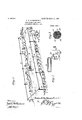
- FIG. 6 is a erspective view showing the system applied to a railway for establishing communication be tween :1 moving tram and a way-station.
- Fig. 7 is a sectional view through a car showingdiagram the car mechanism illustrated Similar reference numerals designate corrfisponding parts in all the figures of the awmgs. 45.
- a water-way 8 is disclosed, upon which a vessel-9 operates.
- Surround- .ing the path of travel of the vessel, and preferably elevated on poles 10, is a coil 11 of considerable magnitude. This coil, as shown in Fig.
- the battery or ot or source of electricity has a connection 18'with one of the leads 14.
- a receiver 19 of the ordinary type has a conwhich is connected by a suitable wire 16 an nection with the same lead 14, to which the battery is connected, and both the receiver and transmitter have connections 21 with the contacts of a switch 22.
- This switch has suitable means, as for instance, a spring 23, which normally maintains the receiver in circuit with the coil 11, as will be evident by reference to Fig. 1, but if the switch is thrown. to break the circuit, it will then cut in the source of electrical energy 15 and the transmitter 17.
- connection 28 with one of the leads of the coil.
- the receiver 29 also has a connection 30 with said lead.
- a switch 31 is connected to the other lead, and is normally held in a position by a spring 32 to maintain a closed circuit through the receiver 29 and the coil, though it may be moved to cut out said receiver and close the circuit through the coil, the source of electrical energy and the-transmitter.
- the switch 22 is moved downwardly to cut out the receiver and throw in the transmitter and source of electrical energy, while the operator upon the boat or vehicle leaving the mechanism in the condition shown in Fig. 2, holds the receiver 29 to his car. If therefore the operator at the shore-station uses the transm1tter in the ordinarymanner, a var ing current corresponding to that passing t ough the coil of great magnitude 11 value, and furthermore experience has demonstratedthattheemploymentofcoilsofdifl erent magnitudes is of great importance, for it has been found that while two small coils can be used to transmit but a short distance, if
- one'large coil of the characterset forth is employed, the other may be very small, and speech or sounds can be transmitted comparativel great distances from one to the other. hese sounds are clearly audible.
- FIG. 4 and 5 The structure disclosed in Figs. 4 and 5 is of the same general character.
- a road-way 32 is disclosed surrounded by a coil 33 of great magnitude that is supported on suitable poles 34.
- the way-station 35 consists of a transmitter 36, a source of electrical energy 37 connected thereto, a receiver 38, and a switch 39, whereby the receiver or the transmitter and source of electrical energy can be thrown into circuit with the coil 33.
- the vehicles 40 Whichoperate on the roadway, are provided with smaller coils 41 and instruments consisting of receivers 42, transmitters 43, sources of electrical energy 44 and switches 45 all arranged in the manner already described. In a system of this kind, it will be evident that the occupant of one vehicle may telephone to the home or waystation, and the messa e can be transmitted to another vehicle.
- a comparatively great coil 46 is supported on o posite sides of the railway 47 by poles 48 an astation 49 has arecelver 50 and a transmitter 51, a source of electrical energy 52 and a switch 53, the last mentioned being employed for throwing either the receiver or the transmitter and source of electrical energy into closed circuit with the coil 46.
- Means 'for communicating between a plurality of stations which. consists of an aerial electrical coil of great magnitude, means for supporting the said coil, a station electrically connected to the great coil and comprising transmitting and receiving mech anism that includes a source of heavy electrical energy, and a plurality of other separate stations simultaneously in coacting relation with the aerial coil, each of said latter stations. com rising a coil of conducting ma terial space from but in coacting relation with said great coil and below the same, and transmitting and receiving mechanism connected to said other coil and including a source of electrical energy.
- Means for communicating between a plurality of. stations which consists of an aerial coil of conducting material of great magnitude, transmitting and receiving mech anism connected to said aerial coil and ineluding a source of heavy electrical energy, a plurality of vehicles movable between the op osite sides or stretches of the great coil, 001 s carried by said vehicles and dis osed 19 within the field of action of the aerial coil,
Landscapes
- Engineering & Computer Science (AREA)
- Signal Processing (AREA)
- Computer Networks & Wireless Communication (AREA)
- Train Traffic Observation, Control, And Security (AREA)
- Current-Collector Devices For Electrically Propelled Vehicles (AREA)
- Road Signs Or Road Markings (AREA)
Description
PATENTED MAY 12, 1908.
N. B. STUBBLEPIELD.
WIRELESS TELEPHONE.
APPLICATION FILED APR. 5, 1907.
3 SHEETS-SHEET 1.
PATENTED MAY 12, 1908.
N. B. STUBBLEFIELD.
WIRELESS TELEPHONE.
APPLIUATION FILED APR. 5, 1907 3 SHEETS-SHEET 2.
aH'oznm No. 887,357. PATENTED MAY 1211908. N. B. STUBBLEFIELD.
WIRELESS TELEPHONE.
APPLICATION FILED APR. 5, 1907.
3 SHEETS-SHEET 3.
amen 6oz UNITED STATES PATENT OFFICE.
NATHAN B. STUBBLEFIELD, OF MURRAY, KENTUCKY,-ASSIGNOR OF TWELVE AND ONE-HALF ONE-HUNDREDTHS TO CONN LINN, FIVE ONE-HUNDREDTHS TO R. DOWNS, FIVE ONE- HUNDREDTHS TO B. F. SCHROADER, FIVE ONE-HUNDREDTHS TO GEORGE C. McLARIN,
' FIVE ONE-HUNDREDTHS TO JOHN P. McELRATH, TWO AND ONE-HALF ONE-HUNDREDTHS TO JEFF D. ROULETT, AND ONE-TWENTIETH TO SAMUEL E. BYNUM, ALL OF MURRAY,
KENTUCKY.
WIRELESS TELEPHONE.
Specification of Letters Patent.
Patented May 12, 1908.
Application filed. April 6, 1907. Serial No. 366,644.
mm, a citizen of the United States, residin at Murra in the county of Galloway an State of entuc have invented a new and Wireless elephone, of which the followmg is a specification.
The present invention relates to means-for electrically transmitting signals from one point to another without the use of connectmg. wires, and more particularly comprehending means for-securing telephonic com munication between moving vehicles and we stations.
e principal object of the invention is to provide simple and practical means of a novel nature whereby clear and audible com munication can be established, said means being sim le and of a character that will per* I nit certam of the station mechanisms to be small and compact.
In the accompan drawings :-Fi ure 1 is aperspective view, s owing means or estabhshing communication between a vessel and a shore station. Fig. 2 is a diagrammatic view of the mechanism mounted on the boat. Fig. 3 is across sectional view on an enlarged scale of the shore coil. Fig. 4 is a rspective view of a road-way, showing a system for establishing communication between road vehicles and a way-station, the latter be' illustrated di ammatically. Fig. 5 is a etail view of a ve icle equipped with one of the instruments, which is shown diagrammatically. 6 is a erspective view showing the system applied to a railway for establishing communication be tween :1 moving tram and a way-station. Fig. 7 is a sectional view through a car showingdiagram the car mechanism illustrated Similar reference numerals designate corrfisponding parts in all the figures of the awmgs. 45. Referring to the embodiment illustrated in Figs. 1, 2 and 3, a water-way 8 is disclosed, upon which a vessel-9 operates. Surround- .ing the path of travel of the vessel, and preferably elevated on poles 10, is a coil 11 of considerable magnitude. This coil, as shown in Fig. 3, consists of an outer casing 12, within which is placed a conducting wire comprising a lurality ofconvolutions 13, each of which is msulated from the other. The terminals 14 of this coil extend to a suitable way-station, and at the station is located a powerful source of electrical energy 15, to
electrically o erated transmitter 17. The battery or ot or source of electricity has a connection 18'with one of the leads 14. A receiver 19 of the ordinary type has a conwhich is connected by a suitable wire 16 an nection with the same lead 14, to which the battery is connected, and both the receiver and transmitter have connections 21 with the contacts of a switch 22. This switch has suitable means, as for instance, a spring 23, which normally maintains the receiver in circuit with the coil 11, as will be evident by reference to Fig. 1, but if the switch is thrown. to break the circuit, it will then cut in the source of electrical energy 15 and the transmitter 17.
An outfit similar to the above, is located on the vehicle or boat 9, but the coil 24 thereof, shown in Fig. 2, is much smaller. As further illustrated in said figure, the mechanism mounted on the boat, consists of a transmitter 25, and a battery or other source of electrical energy 26 electrically connected, as
shown at 27 and having a connection 28 with one of the leads of the coil. The receiver 29 also has a connection 30 with said lead. A switch 31 is connected to the other lead, and is normally held in a position by a spring 32 to maintain a closed circuit through the receiver 29 and the coil, though it may be moved to cut out said receiver and close the circuit through the coil, the source of electrical energy and the-transmitter.
In this system, if it is desired to transmit from one station, as for instance, the shorestation, the switch 22 is moved downwardly to cut out the receiver and throw in the transmitter and source of electrical energy, while the operator upon the boat or vehicle leaving the mechanism in the condition shown in Fig. 2, holds the receiver 29 to his car. If therefore the operator at the shore-station uses the transm1tter in the ordinarymanner, a var ing current corresponding to that passing t ough the coil of great magnitude 11 value, and furthermore experience has demonstratedthattheemploymentofcoilsofdifl erent magnitudes is of great importance, for it has been found that while two small coils can be used to transmit but a short distance, if
one'large coil of the characterset forth is employed, the other may be very small, and speech or sounds can be transmitted comparativel great distances from one to the other. hese sounds are clearly audible.
The structure disclosed in Figs. 4 and 5 is of the same general character. A road-way 32 is disclosed surrounded by a coil 33 of great magnitude that is supported on suitable poles 34. The way-station 35 consists of a transmitter 36, a source of electrical energy 37 connected thereto, a receiver 38, and a switch 39, whereby the receiver or the transmitter and source of electrical energy can be thrown into circuit with the coil 33. The vehicles 40, Whichoperate on the roadway, are provided with smaller coils 41 and instruments consisting of receivers 42, transmitters 43, sources of electrical energy 44 and switches 45 all arranged in the manner already described. In a system of this kind, it will be evident that the occupant of one vehicle may telephone to the home or waystation, and the messa e can be transmitted to another vehicle. that communication can be established between two moving vehicles or between a waystation and any vehicle desired which is within the range of the homeor waystation. The system is also capable of use in connection with railways, and in Figs. 6 and 7, such a' system is disclosed in connection therewith. A comparatively great coil 46 is supported on o posite sides of the railway 47 by poles 48 an astation 49 has arecelver 50 and a transmitter 51, a source of electrical energy 52 and a switch 53, the last mentioned being employed for throwing either the receiver or the transmitter and source of electrical energy into closed circuit with the coil 46. One
' T us it will be evident construction, operation, and many advantages of the herein described invention will be apparent to those skilled in the art, without further description, and it will be understood that various changes in-the size, shape, proportion, and minor details of construction, may be resorted to without departing from the spirit or sacrificing any of the advantages o the invention.
Having thus fully described my invention, what I claim as new, and desire to secure by Letters Patent, is:
1. In a system of the character described, the combination with a vehicle, of a comparatively small coil of conducting material mounted thereon, electrical transmitting and receivin mechanism including a source of electrica energy connected to the small coil and carried by the vehicle, a stationary aerial coil of much greater magnitude than the small coil havlng its opposite stretches or sides extending alon t e p osite sides of the path of travel oft e vehic e and elevated above the same and above the vehicle coil, and electrical transmitting and receiving mechanism connected to the greater coil and including a source of heavy electrical current.
2. In a system of the character described, the combination with a vehicle, of a coil of conducting material mounted thereon, electrical transmitting mechanism, asource of electrical energy connected thereto, receiving mechanism, means for connecting either the transmitting mechanism and source of electrical energy or the receiving mechanism to the .coil, a stationary coil of greater mag-' nitude surrounding the path of travel of, the vehicle and comprising a plurality of convolutions of conducting material, the diflerent convolutions' beingmsulated one from the other, means for sup orting the coil in an elevated position, e ectrical transmitting mechanism, a source of great electrical-energy connected to said transmitting mechanism, electrical receiving mechanism, and
means for electrically connecting either the transmitting mechanism and source of electrical ener the said coi of greater magnltude.
3. Means 'for communicating between a plurality of stations which. consists of an aerial electrical coil of great magnitude, means for supporting the said coil, a station electrically connected to the great coil and comprising transmitting and receiving mech anism that includes a source of heavy electrical energy, and a plurality of other separate stations simultaneously in coacting relation with the aerial coil, each of said latter stations. com rising a coil of conducting ma terial space from but in coacting relation with said great coil and below the same, and transmitting and receiving mechanism connected to said other coil and including a source of electrical energy.
or the receiving mechanism to 4. Means for communicating between a plurality of. stations which consists of an aerial coil of conducting material of great magnitude, transmitting and receiving mech anism connected to said aerial coil and ineluding a source of heavy electrical energy, a plurality of vehicles movable between the op osite sides or stretches of the great coil, 001 s carried by said vehicles and dis osed 19 within the field of action of the aerial coil,
and transmitting and receiving mechanism mounted on each vehicle and including a source of electrical energy.
In testimony, that I claim the foregoing as my own, I have hereto afl'ixed my slgna- 15 ture in the presence of two witnesses.
N A'IHAN B. STUBBLEFIELD.
Witnesses:
J. P. McELRA'rn, J. II. COLEMAN.
Priority Applications (1)
| Application Number | Priority Date | Filing Date | Title |
|---|---|---|---|
| US36654407A US887357A (en) | 1907-04-05 | 1907-04-05 | Wireless telephone. |
Applications Claiming Priority (1)
| Application Number | Priority Date | Filing Date | Title |
|---|---|---|---|
| US36654407A US887357A (en) | 1907-04-05 | 1907-04-05 | Wireless telephone. |
Publications (1)
| Publication Number | Publication Date |
|---|---|
| US887357A true US887357A (en) | 1908-05-12 |
Family
ID=2955790
Family Applications (1)
| Application Number | Title | Priority Date | Filing Date |
|---|---|---|---|
| US36654407A Expired - Lifetime US887357A (en) | 1907-04-05 | 1907-04-05 | Wireless telephone. |
Country Status (1)
| Country | Link |
|---|---|
| US (1) | US887357A (en) |
Cited By (9)
| Publication number | Priority date | Publication date | Assignee | Title |
|---|---|---|---|---|
| US2442851A (en) * | 1940-08-03 | 1948-06-08 | Farnsworth Res Corp | Traffic signaling system |
| US2460511A (en) * | 1943-05-27 | 1949-02-01 | Link Aviation Inc | Automatic radio signaling means for aviation trainers |
| US2494451A (en) * | 1946-01-31 | 1950-01-10 | Rca Corp | Personal call system |
| US2636113A (en) * | 1946-03-09 | 1953-04-21 | Standard Telephones Cables Ltd | Fixed route vehicular location and communicating system |
| US2751534A (en) * | 1951-11-14 | 1956-06-19 | Jefferson Sidney | Inductively effected remote control for plural electric motors |
| US2870435A (en) * | 1954-05-26 | 1959-01-20 | Graaf Nicolaas Robert De | Calling system |
| US2983903A (en) * | 1956-11-13 | 1961-05-09 | Philipps Electronics Corp | Crystal vibrated reed and receiver and system of communication using same |
| US20090091754A1 (en) * | 2007-10-05 | 2009-04-09 | Jingyun Zhang | Compact Spectrometer |
| US8345226B2 (en) | 2007-11-30 | 2013-01-01 | Jingyun Zhang | Spectrometers miniaturized for working with cellular phones and other portable electronic devices |
-
1907
- 1907-04-05 US US36654407A patent/US887357A/en not_active Expired - Lifetime
Cited By (11)
| Publication number | Priority date | Publication date | Assignee | Title |
|---|---|---|---|---|
| US2442851A (en) * | 1940-08-03 | 1948-06-08 | Farnsworth Res Corp | Traffic signaling system |
| US2460511A (en) * | 1943-05-27 | 1949-02-01 | Link Aviation Inc | Automatic radio signaling means for aviation trainers |
| US2494451A (en) * | 1946-01-31 | 1950-01-10 | Rca Corp | Personal call system |
| US2636113A (en) * | 1946-03-09 | 1953-04-21 | Standard Telephones Cables Ltd | Fixed route vehicular location and communicating system |
| US2751534A (en) * | 1951-11-14 | 1956-06-19 | Jefferson Sidney | Inductively effected remote control for plural electric motors |
| US2870435A (en) * | 1954-05-26 | 1959-01-20 | Graaf Nicolaas Robert De | Calling system |
| US2983903A (en) * | 1956-11-13 | 1961-05-09 | Philipps Electronics Corp | Crystal vibrated reed and receiver and system of communication using same |
| US20090091754A1 (en) * | 2007-10-05 | 2009-04-09 | Jingyun Zhang | Compact Spectrometer |
| US7817274B2 (en) | 2007-10-05 | 2010-10-19 | Jingyun Zhang | Compact spectrometer |
| US8345226B2 (en) | 2007-11-30 | 2013-01-01 | Jingyun Zhang | Spectrometers miniaturized for working with cellular phones and other portable electronic devices |
| US8537343B2 (en) | 2007-11-30 | 2013-09-17 | Jingyun Zhang | Spectrometer miniaturized for working with cellular phones and other portable electronic devices |
Similar Documents
| Publication | Publication Date | Title |
|---|---|---|
| US887357A (en) | Wireless telephone. | |
| US2109475A (en) | Control system | |
| US465971A (en) | Means for transmitting signals electrically | |
| US2394444A (en) | Induction radio system | |
| US2883522A (en) | Mobile communication system with carrier signal strength control | |
| US1975932A (en) | Sound-receiving and transmitting system | |
| US975933A (en) | Telephone-repeater. | |
| US334188A (en) | phelps | |
| US918537A (en) | Train-position indicator. | |
| US334189A (en) | phelps | |
| US795762A (en) | Wireless telegraphy. | |
| US353940A (en) | hayes | |
| US979144A (en) | Transmission and receipt of electrical energy. | |
| USRE12141E (en) | Reissued aug | |
| GB190920230A (en) | Improvements in Wireless Telegraph Transmitting and Receiving Stations. | |
| US1101915A (en) | Wireless signaling. | |
| US334186A (en) | phelps | |
| US1308910A (en) | Train-telephone system | |
| US1216887A (en) | Inductive wireless-telephone system for railroads and the like. | |
| US1737089A (en) | Signaling system | |
| US631271A (en) | Telephone. | |
| US775846A (en) | Wireless telegraph. | |
| US469865A (en) | Telephone system | |
| US714834A (en) | Apparatus for selective electric signaling. | |
| US1045413A (en) | Inductive telephone and telegraphic installation. |