US8869934B2 - Method, apparatus, and arrangement for a lifeline system - Google Patents
Method, apparatus, and arrangement for a lifeline system Download PDFInfo
- Publication number
- US8869934B2 US8869934B2 US12/631,996 US63199609A US8869934B2 US 8869934 B2 US8869934 B2 US 8869934B2 US 63199609 A US63199609 A US 63199609A US 8869934 B2 US8869934 B2 US 8869934B2
- Authority
- US
- United States
- Prior art keywords
- shuttle member
- shuttle
- line
- upper portion
- attachment
- Prior art date
- Legal status (The legal status is an assumption and is not a legal conclusion. Google has not performed a legal analysis and makes no representation as to the accuracy of the status listed.)
- Active, expires
Links
Images


Classifications
-
- A—HUMAN NECESSITIES
- A62—LIFE-SAVING; FIRE-FIGHTING
- A62B—DEVICES, APPARATUS OR METHODS FOR LIFE-SAVING
- A62B35/00—Safety belts or body harnesses; Similar equipment for limiting displacement of the human body, especially in case of sudden changes of motion
- A62B35/0043—Lifelines, lanyards, and anchors therefore
- A62B35/0056—Horizontal lifelines
-
- A—HUMAN NECESSITIES
- A62—LIFE-SAVING; FIRE-FIGHTING
- A62B—DEVICES, APPARATUS OR METHODS FOR LIFE-SAVING
- A62B35/00—Safety belts or body harnesses; Similar equipment for limiting displacement of the human body, especially in case of sudden changes of motion
- A62B35/0081—Equipment which can travel along the length of a lifeline, e.g. travelers
- A62B35/0087—Arrangements for bypassing lifeline supports without lanyard disconnection
-
- E—FIXED CONSTRUCTIONS
- E04—BUILDING
- E04G—SCAFFOLDING; FORMS; SHUTTERING; BUILDING IMPLEMENTS OR AIDS, OR THEIR USE; HANDLING BUILDING MATERIALS ON THE SITE; REPAIRING, BREAKING-UP OR OTHER WORK ON EXISTING BUILDINGS
- E04G21/00—Preparing, conveying, or working-up building materials or building elements in situ; Other devices or measures for constructional work
- E04G21/32—Safety or protective measures for persons during the construction of buildings
- E04G21/3204—Safety or protective measures for persons during the construction of buildings against falling down
Definitions
- the present invention relates generally to fall protection systems and arrangements, and in particular to a method, apparatus and arrangement for use in connection with a lifeline system, preferably a horizontal lifeline system, and further to a shuttle member, a shuttle member arrangement, and a method of passing such shuttle members during use in such a lifeline system.
- One particular type of lifeline system that can be installed as a portable, temporary arrangement is a horizontal lifeline system that includes an elongate line, e.g., a cable or the like, attached between two anchor points and extending along a structure.
- an elongate line e.g., a cable or the like
- some attaching device such as a shuttle member that is movable along the line.
- the lanyard and the elongate line will prevent the user from falling to the ground.
- multiple workers will be attached to the same line using their own separate and distinct attaching device.
- a portable, temporary horizontal lifeline system is often preferable, based at least in part upon the following: (1) the time savings realized in installing and taking down a temporary system; (2) the ease and convenience of installation and removal of a temporary system; and (3) the ease of manipulating and operating a temporary system at elevated positions and heights.
- more than one worker is often attached to a single lifeline, which leads to the need for workers to pass each other.
- both workers typically must move to one end of the lifeline system, each respectively remove their attaching device and connect it to a temporary anchor point, and then re-attach the devices in the preferred order to allow the workers to “pass” each other. This obviously leads to increased time, decreased efficiency, and a greater possibility of some mishap when the workers are making the switch.
- the present invention provides methods, apparatus and arrangements for a lifeline system that overcome some or all of the drawbacks and deficiencies existing in known systems.
- the present invention provides methods, apparatus and arrangements for a lifeline system that permit the safe passage of multiple attaching devices connected to the same line or cable.
- the present invention provides methods, apparatus and arrangements for a lifeline system that lead to increased safety, and are easy to implement and utilize.
- the present invention provides methods, apparatus and arrangements for a lifeline system that are useful in connection with new or existing lifeline systems, such as a portable, temporary horizontal lifeline system.
- the present invention is directed to a shuttle member for a lifeline system having at least one elongate line attached between at least two anchorage points.
- the shuttle member includes: a body having: (i) an upper portion configured for attachment to the line by at least partially surrounding the line; (ii) an intermediate portion that, together with the upper portion, defines at least one passage slit; (iii) an attachment portion configured for attachment of at least a portion of an attaching device, and wherein the at least one passage slit is sized such that the elongate line cannot pass therethrough, even under the forces of a fall event.
- the present invention is utilized in a lifeline system having at least one elongate line attached between at least two anchorage points.
- the present invention provides a shuttle member passage arrangement, which includes a first shuttle member and a second shuttle member, each having a body with: (i) an upper portion configured for direct or indirect attachment to the line; (i) an intermediate portion that, together with the upper portion, defines at least one passage slit; and (iii) an attachment portion configured for attachment of at least a portion of an attaching device.
- the first shuttle member is configured to permit at least a portion of the upper portion of the first shuttle member to move through an inner area and passage slit of the second shuttle member from a side thereof, thereby permitting the first shuttle member to pass the second shuttle member.
- the present invention is directed to a passing method for a first shuttle member and a second shuttle member in a lifeline system having at least one elongate line attached between at least two anchorage points.
- the method includes: attaching the first shuttle member and the second shuttle member to the line of the lifeline system; entering at least a portion of the first shuttle member into an inner area of the second shuttle member at a first side thereof; and passing the first shuttle member entirely through the inner area of the second shuttle member, thereby permitting the first shuttle member to pass the second shuttle member.
- FIG. 1 is a schematic view of a lifeline system according to the prior art
- FIG. 2 is a schematic view of one embodiment of a lifeline system according to the principles of the present invention.
- FIG. 3( a ) is a schematic view of a first position of two shuttle members according to the principles of the present invention
- FIG. 3( b ) is a schematic view of an intermediate position of the shuttle members of FIG. 3( a );
- FIG. 3( c ) is a schematic view of an intermediate passing position of the shuttle members of FIG. 3( a );
- FIG. 3( d ) is a schematic view of a further intermediate passing position of the shuttle members of FIG. 3( a );
- FIG. 3( e ) is a schematic view of a final passed position of the shuttle members of FIG. 3( a );
- FIG. 4 is a side sectional view of two shuttle members according to the principles of the present invention in a passing position
- FIG. 5 is a side view of one embodiment of a shuttle member according to the principles of the present invention.
- FIG. 6 is a side view of another embodiment of a shuttle member according to the principles of the present invention.
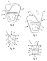
- FIG. 7( a ) is a front view of a further embodiment of a shuttle member according to the principles of the present invention.
- FIG. 7( b ) is a side view of the shuttle member of FIG. 7( a );
- FIG. 8 is a perspective view of another embodiment of a shuttle member according to the principles of the present invention.
- FIG. 9 is a perspective view of a further embodiment of a shuttle member according to the principles of the present invention.
- FIG. 10 is a front view of a still further embodiment of a shuttle member according to the principles of the present invention.
- FIG. 11 is a front view of another embodiment of a shuttle member according to the principles of the present invention.
- FIG. 12 is a front view of another embodiment of a shuttle member according to the principles of the present invention.
- FIG. 13 is a front view of a further embodiment of a shuttle member according to the principles of the present invention.
- FIG. 14 is a side view of a further embodiment of a shuttle member according to the principles of the present invention.
- FIG. 15 is a side view of a still further embodiment of a shuttle member according to the principles of the present invention.
- FIG. 16 is a front view of another embodiment of a shuttle member according to the principles of the present invention as attached to a lifeline system.
- the terms “end”, “upper”, “lower”, “right”, “left”, “vertical”, “horizontal”, “top”, “bottom”, “lateral”, “longitudinal” and derivatives thereof shall relate to the invention as it is oriented in the drawing figures.
- the invention may assume various alternative variations and step sequences, except where expressly specified to the contrary.
- the specific devices and processes illustrated in the attached drawings, and described in the following specification are simply exemplary embodiments of the invention. Hence, specific dimensions and other physical characteristics related to the embodiments disclosed herein are not to be considered as limiting.
- the term “end” may refer to the extreme distal portion or the area near or adjacent that portion.
- the invention may assume various alternative variations and step sequences, except where expressly specified to the contrary.
- this lifeline system LS includes multiple anchorage points AP attached to or positioned on some part of a sturdy structure, such as a beam B.
- An elongate line L is attached between two opposing anchorage points AP situated on opposing beams B. It is this line L to which a user U is removably connected or operationally engaged.
- the user U attaches a shock-absorbing lanyard Y or other attachment device directly to the line L.
- This shock-absorbing lanyard Y includes a lanyard line YL that is attached at one end to the user U (normally to a full body harness worn by the user U).
- At the other end of the lanyard line YL is some lanyard attaching structure YA, normally including a body with a clip or other arrangement for removable attachment to the line L.
- the lanyard attachment structure YA may be attached to a shuttle member SM, which is attached to the line L. This shuttle member SM provides additional and effective functionality by allowing the user U to move easily along the line L in the lifeline systems LS.
- the lanyard attaching structure YA must be disconnected from the shuttle members SM and reconnected on the other side of each other, since the shuttle members SM cannot pass each other on the line L. While this mechanical disconnection and reconnection may be simple to accomplish in operation, it is unsafe to perform such an operation at any point along the line L. Instead, both users U must move to one side or the other of the lifeline system LS, such as towards one or the other of the beams B that has the anchorage points AP.
- one or both of the users U must disconnect the lanyard Y from the line L, connect it to another anchorage point AP on the beam B and then reconnect after appropriately arranging the positions of the respective lanyards Y to the adjacent shuttle members SM of the users U.
- Such an operation leads to increased time, decreased efficiency, and a greater possibility of some mishap while the users U are making the switch.
- the present invention provides a shuttle member 10 for use in connection with the above-discussed lifeline system LS.
- This shuttle member 10 includes an upper portion 12 that is configured or adapted for attachment to the line L by at least partially surrounding the line L.
- an intermediate portion 14 together with the upper portion 12 , defines at least one passage slit 16 .
- the passage slit 16 is sized such that the line L cannot pass therethrough, even under the forces generated during a fall event.
- the shuttle member 10 includes an attachment portion 18 that is adapted or configured for attachment to at least a portion of an attaching device, such as the lanyard attaching structure YA.
- an attaching device such as the lanyard attaching structure YA.
- any such attaching device that is configured for removable attachment to the shuttle member 10 is envisioned.
- FIGS. 3( a )- 3 ( e ) and 4 The passing operation is illustrated in FIGS. 3( a )- 3 ( e ) and 4 .
- these drawings illustrate a first shuttle member 10 - 2 and a second shuttle member 10 - 2 passing each other.
- the first shuttle member 10 - 1 starts in a first position P 1
- the second shuttle member 10 - 2 starts in a second position P 2 .
- the user of the first shuttle member 10 - 1 wishes to pass the user of the second shuttle member 10 - 2 in order to accomplish some task at the other end of the lifeline system LS.
- FIG. 3( a ) shows the first shuttle member 10 - 1 and second shuttle member 10 - 2 in their original positions P 1 , P 2 respectively.
- the first shuttle member 10 - 1 is rotated (approximately 180°) with respect to the second shuttle member 10 - 2 .
- the first shuttle member 10 - 1 is rotated or moved from the first position P 1 to a third position P 3 . See FIG. 3( b ).
- first shuttle member 10 - 1 is moved into an inner area 20 of the second shuttle member 10 - 2 (which also means that a portion of the second shuttle member 10 - 2 would be positioned within the inner area 20 of the first shuttle member 10 - 1 .
- this positioning and movement into the inner area 20 is accomplished through the positioning and alignment of the passage slits 16 of each shuttle member 10 - 1 , 10 - 2 .
- bodies 22 of each shuttle member 10 - 1 , 10 - 2 are moved through and along the passage slit 16 of the other shuttle member 10 - 1 , 10 - 2 .
- the first shuttle member 10 - 1 is rotated or moved back to its original orientation, with the result being that the first shuttle member 10 - 1 is now in the second position P 2 , and the second shuttle member 10 - 2 is in the first position P 1 .
- the shuttle members 10 - 1 , 10 - 2 remain in an attached or connected position with respect to the line L of the lifeline system LS.
- the line L is still at least partially surrounded by each of the upper portions 12 of the shuttle members 10 - 1 , 10 - 2 , i.e., the line L is located at least partially within the inner area 20 of each shuttle member 10 - 1 , 10 - 2 . Accordingly, both users remain safely connected to the line L in the lifeline system LS during passage, such that, in the event of a fall, the shuttle member 10 (and the attaching device for lanyard Y) are still effective in the necessary fall arrest function.
- the present invention provides various preferred and non-limiting structures and arrangements, as illustrated in FIGS. 5-16 . Each of these various preferred and non-limiting embodiments of the shuttle member 10 will be discussed hereinafter.
- the upper portion 12 and the intermediate portion 14 form a substantially C-shaped structure 24 that defines the passage slit 16 .
- the passage slit 16 is sized such that the line L cannot pass therethrough, even under the forces generated by a fall.
- a roller (not shown) can be operationally engaged with or within the upper portion 12 of the shuttle member 10 for use in contacting the line L during normal operation of the shuttle member 10 .
- the use of an additional mechanical structure, e.g., a roller is not optimal.
- the upper portion 12 includes an inner surface 26 that is adapted, configured, sized, and/or shaped to contact the line L.
- the shuttle member 10 glides along the line L. Still further, and in order to enhance this sliding or gliding function, at least a portion of the inner surface 26 of the upper portion 12 can be smooth, rounded, shaped, coated, or the like. Such configurations and arrangements are used to decrease friction, thereby increasing the user's ability to effectively function while attached to the lifeline system LS.
- the attachment portion 18 of the shuttle member 10 is in the form of an extension 28 extending from the intermediate portion 14 .
- this extension 28 includes an opening 30 that is sized and shaped so as to permit connection of an attaching portion (e.g., the lanyard attaching structure YA) thereto.
- an attaching portion e.g., the lanyard attaching structure YA
- FIG. 6 A further preferred and non-limiting embodiment is illustrated in FIG. 6 .
- the upper portion 12 is in the form of a hook 32
- the intermediate portion 14 is in the form of an extending tongue 34 .
- the hook 32 and the extending tongue 34 together define the passage slit 16 .
- the passage slit 16 is smaller than the diameter of the line L.
- This embodiment also uses the extension 28 and opening 30 discussed above.
- FIG. 7( a )- 7 ( b ) A further embodiment is illustrated in FIG. 7( a )- 7 ( b ).
- the hook 32 and extending tongue 34 are utilized.
- the hook 32 includes rounded or contoured edges 36
- the body 22 includes tapered (or angled) edges 38
- the extending tongue 34 also includes certain edges 40 that are tapered or angled.
- the shapes and contours of the upper portion 12 , intermediate portion 14 , passage slit 16 , and/or body 22 can be configured, sized, and/or shaped so as to begin to urge or fully urge the first shuttle member 10 - 1 to a rotated position with respect to the second shuttle member 10 - 2 , such that they are aligned for passage.
- the body 22 (or any portions thereof) can be specifically configured to allow for rotation and passage upon contact without the need for user interaction, or with minimal interaction.
- the size and shape of the body 22 (or portions thereof) are designed and configured to only begin to urge the shuttle members 10 to the appropriate positions, but require final manual positioning and passage by one or both of the users.
- FIG. 8 A further preferred and non-limiting embodiment is illustrated in FIG. 8 .
- the above-discussed shaped hook 32 and body 22 are used.
- the edges 40 of the extending tongue 34 are formed such that the tongue 34 is in a substantially semi-circular shape (when viewed from above).
- the extending tongue 34 is a substantially flat member when viewed from the front. Again, by the use of the semi-circular shape of the extending tongue 34 , together with the other shaped edges and surfaces of the shuttle member 10 , easier orientation and passage is achieved.
- FIG. 9 A similar arrangement is illustrated in FIG. 9 .
- the hook 32 is offset, such that a first side edge 42 of the hook 32 has a longer dimension than a second side edge 44 of the hook 32 . This provides additional rotation properties, and may also lend to further structural and strength advantages.
- the body 22 is in a substantially U-shaped structure, where the bottom edge 46 of the body 22 is rounded.
- the opening 30 in the extension 28 of the attachment portion 18 is likewise rounded. The rounded shape of the opening 30 allows for greater movement and angular variation between the attaching structure YA of the lanyard Y and the shuttle member 10 during operation and use thereof.
- the hook 32 and extending tongue 34 are similar in contour and shape as that of the embodiment of FIGS. 7( a )- 7 ( b ).
- the edges 38 of the body 22 are substantially straight.
- this embodiment includes guard members 48 extending from these side edges 38 near a bottom area thereof.
- these guard members 48 are positioned substantially adjacent the opening 30 , and further, these guard members 48 taper inward. Based upon the position, orientation, and shape of these guard members 48 , the lanyard attaching structure YA that is attached to the opening 30 is protected when and if two shuttle members 10 contact each other. Such an arrangement would prevent inadvertent detachment of the lanyard Y (or attaching device) from the shuttle member 10 , and thus the lifeline system LS.
- FIG. 12 A still further preferred and non-limiting embodiment of the shuttle member 10 according to the present invention is illustrated in FIG. 12 .
- the body 22 is a substantially square-shaped structure, and the opening 30 is likewise in a square-shaped form.
- the hook 32 has a flatter, wider shape than the embodiments of FIGS. 7-11 .
- the extending tongue 34 includes edges 40 that are curved downward in a similar manner as the angled edges 40 of the extending tongue 34 of the embodiments in FIGS. 7 and 11 .
- the opening 30 , as well as the bordering bottom edge 46 of the body 22 are curved so as to provide multiple curved surfaces. Such an arrangement would assist in directing the lanyard attaching structure YA over this curved area as the user moves back and forth along the line L of the lifeline system LS.
- the front surface 50 of a portion of the body 22 may be tapered or angled.
- a different extension angle is applied to the lanyard attaching structure YA and, thus, the lanyard Y. Again, this may assist in facilitating easier movement along the line L of the lifeline system LS.
- the front surface 50 of the attachment portion 18 can be curved, as illustrated in the preferred and non-limiting embodiment of FIG. 15 .
- the extending tongue 34 is also curved upwards towards the hook 32 .
- the material used to make the shuttle member 10 can be chosen based upon the strength requirements, the size, shape and type of line L, and/or the environment in which the user U is utilizing the shuttle member 10 .
- the shuttle member may be formed in whole or in part from a metal, a semi-metal, a powdered metal, a synthetic material, a stamped material, a molded material, or the like. Any suitable material of construction is envisioned.
- the shuttle member 10 is attached to the line L in the lifeline system LS.
- the lanyard attaching structure YA is then attached or connected to the opening 30 , i.e., the attachment portion 18 .
- the lanyard attaching structure YA includes a clip or carabiner C that is removably attachable through the opening 30 .
- the lanyard line YL is permanently attached to the clip C, such as through the use of connecting loops on the clip C and the lanyard line YL.
- the present invention provides a method, apparatus, and arrangement for use in connection with a lifeline system LS that allows for the safe passage of users U using lanyard attaching devices Y, which are attached to the shuttle member 10 .
- safe passage is permitted without the time constraints of known arrangements, and without diminishing the worker's safety.
- the present invention can be used with any type or style of lifeline system (whether horizontal or vertical, existing or new, temporary or permanent), the present invention is particularly useful in connection with a portable, temporary horizontal lifeline system LS.
Landscapes
- Engineering & Computer Science (AREA)
- Architecture (AREA)
- Health & Medical Sciences (AREA)
- General Health & Medical Sciences (AREA)
- Business, Economics & Management (AREA)
- Emergency Management (AREA)
- Mechanical Engineering (AREA)
- Civil Engineering (AREA)
- Structural Engineering (AREA)
- Emergency Lowering Means (AREA)
- Devices Affording Protection Of Roads Or Walls For Sound Insulation (AREA)
Abstract
Description
Claims (20)
Priority Applications (8)
| Application Number | Priority Date | Filing Date | Title |
|---|---|---|---|
| US12/631,996 US8869934B2 (en) | 2009-05-20 | 2009-12-07 | Method, apparatus, and arrangement for a lifeline system |
| AU2010249942A AU2010249942B2 (en) | 2009-05-20 | 2010-05-06 | Method, apparatus and arrangement for a lifeline system |
| PCT/US2010/033862 WO2010135088A1 (en) | 2009-05-20 | 2010-05-06 | Method, apparatus and arrangement for a lifeline system |
| CN201080022585.7A CN102596327B (en) | 2009-05-20 | 2010-05-06 | Method, apparatus, and arrangement for a lifeline system |
| MX2011012217A MX2011012217A (en) | 2009-05-20 | 2010-05-06 | Method, apparatus and arrangement for a lifeline system. |
| EP10719177.7A EP2432563B1 (en) | 2009-05-20 | 2010-05-06 | Method, apparatus and arrangement for a lifeline system |
| BRPI1007673A BRPI1007673B1 (en) | 2009-05-20 | 2010-05-06 | shuttle member, lifeline system and passing method |
| CL2011002910A CL2011002910A1 (en) | 2009-05-20 | 2011-11-18 | Swinging element of a lifeline system that has at least one elongated line connected between at least two anchor points that comprises a body that has an upper part configured to connect to the line surrounding at least partially the line, a middle part, a connected part; and system. |
Applications Claiming Priority (2)
| Application Number | Priority Date | Filing Date | Title |
|---|---|---|---|
| US21670909P | 2009-05-20 | 2009-05-20 | |
| US12/631,996 US8869934B2 (en) | 2009-05-20 | 2009-12-07 | Method, apparatus, and arrangement for a lifeline system |
Publications (2)
| Publication Number | Publication Date |
|---|---|
| US20100294590A1 US20100294590A1 (en) | 2010-11-25 |
| US8869934B2 true US8869934B2 (en) | 2014-10-28 |
Family
ID=43123834
Family Applications (1)
| Application Number | Title | Priority Date | Filing Date |
|---|---|---|---|
| US12/631,996 Active 2032-05-07 US8869934B2 (en) | 2009-05-20 | 2009-12-07 | Method, apparatus, and arrangement for a lifeline system |
Country Status (8)
| Country | Link |
|---|---|
| US (1) | US8869934B2 (en) |
| EP (1) | EP2432563B1 (en) |
| CN (1) | CN102596327B (en) |
| AU (1) | AU2010249942B2 (en) |
| BR (1) | BRPI1007673B1 (en) |
| CL (1) | CL2011002910A1 (en) |
| MX (1) | MX2011012217A (en) |
| WO (1) | WO2010135088A1 (en) |
Cited By (2)
| Publication number | Priority date | Publication date | Assignee | Title |
|---|---|---|---|---|
| USD813651S1 (en) | 2016-06-29 | 2018-03-27 | Tenacious Holdings, Inc. | Lanyard with carabiner |
| US20210260417A1 (en) * | 2020-02-21 | 2021-08-26 | Arlen Paul Grant | Lifeline Bypass Shuttle |
Families Citing this family (5)
| Publication number | Priority date | Publication date | Assignee | Title |
|---|---|---|---|---|
| US20100193287A1 (en) * | 2009-02-05 | 2010-08-05 | Kyler Nathan Storm | Motion bicycle learning / handicap safety harness |
| JP5775380B2 (en) * | 2011-06-27 | 2015-09-09 | ジャパンマリンユナイテッド株式会社 | Fall prevention device and tank for floating structure |
| US10060146B2 (en) * | 2014-04-07 | 2018-08-28 | Conxtech, Inc. | I-beam-attachable lifeline system |
| SE538034C2 (en) * | 2014-06-04 | 2016-02-16 | Atl Ltd | Security rail to protect a person from falls as well as runners and security systems with such a rail |
| US10420967B2 (en) | 2015-08-28 | 2019-09-24 | Safetylink Pty Ltd | Shuttle device |
Citations (17)
| Publication number | Priority date | Publication date | Assignee | Title |
|---|---|---|---|---|
| US4699245A (en) * | 1986-06-27 | 1987-10-13 | Ets Alfred Herlicq & Fils | Safety device for working at great heights |
| US4790410A (en) * | 1986-12-23 | 1988-12-13 | Barrow Hepburn Equipment Ltd. | Safety track support and coupling |
| US5042391A (en) * | 1990-03-14 | 1991-08-27 | Kahl Scientific Instrument Corporation | Cable-guided messenger |
| US5279385A (en) * | 1991-05-21 | 1994-01-18 | Barrow Hepburn Sala Ltd. | Fall-arrest apparatus |
| US5297651A (en) * | 1993-04-28 | 1994-03-29 | Swingstage Limited | Safety load transfer device and system |
| US5350037A (en) * | 1993-05-24 | 1994-09-27 | Skymaster, Inc. | Workperson safety restraint system |
| US5653172A (en) * | 1992-05-07 | 1997-08-05 | Roschier; Markus | Transport system for travelling crabs |
| US5979599A (en) * | 1996-12-17 | 1999-11-09 | Noles; Larry J. | Track transport system, track-support bracket, and track-traveling apparatus |
| US20020050421A1 (en) * | 2000-09-13 | 2002-05-02 | Dalloz Fall Protection | Sliding member for use with a life-line cross-reference to related applications |
| GB2370312A (en) | 2000-11-29 | 2002-06-26 | Uniline Safety Systems Ltd | Attachment device for a safety line |
| US6488118B1 (en) * | 2000-04-27 | 2002-12-03 | John A. Corriveau | Fall arrest bypass device and method for using same |
| US20070119653A1 (en) * | 2003-10-21 | 2007-05-31 | Kevin Brown | Fall arrest device and system incorporating the same |
| EP1900394A1 (en) | 2006-09-18 | 2008-03-19 | Comercial Igena, Sa | Intermediate support for a life line |
| US7347300B2 (en) * | 2001-05-11 | 2008-03-25 | Latchways Plc | Safety line traveller and support |
| WO2009133361A1 (en) | 2008-04-28 | 2009-11-05 | Latchways Plc | Safety line traveller and support |
| EP2145651A1 (en) | 2008-07-16 | 2010-01-20 | Faszinatour Touristik-Trainig-Event GmbH | Connecting element for a securing device |
| US8001904B2 (en) * | 2007-06-13 | 2011-08-23 | Exponent Challenge Technology | Fall arrest assembly |
-
2009
- 2009-12-07 US US12/631,996 patent/US8869934B2/en active Active
-
2010
- 2010-05-06 MX MX2011012217A patent/MX2011012217A/en active IP Right Grant
- 2010-05-06 AU AU2010249942A patent/AU2010249942B2/en active Active
- 2010-05-06 EP EP10719177.7A patent/EP2432563B1/en active Active
- 2010-05-06 BR BRPI1007673A patent/BRPI1007673B1/en active IP Right Grant
- 2010-05-06 CN CN201080022585.7A patent/CN102596327B/en active Active
- 2010-05-06 WO PCT/US2010/033862 patent/WO2010135088A1/en not_active Ceased
-
2011
- 2011-11-18 CL CL2011002910A patent/CL2011002910A1/en unknown
Patent Citations (19)
| Publication number | Priority date | Publication date | Assignee | Title |
|---|---|---|---|---|
| US4699245A (en) * | 1986-06-27 | 1987-10-13 | Ets Alfred Herlicq & Fils | Safety device for working at great heights |
| US4790410A (en) * | 1986-12-23 | 1988-12-13 | Barrow Hepburn Equipment Ltd. | Safety track support and coupling |
| US5042391A (en) * | 1990-03-14 | 1991-08-27 | Kahl Scientific Instrument Corporation | Cable-guided messenger |
| US5279385A (en) * | 1991-05-21 | 1994-01-18 | Barrow Hepburn Sala Ltd. | Fall-arrest apparatus |
| US5653172A (en) * | 1992-05-07 | 1997-08-05 | Roschier; Markus | Transport system for travelling crabs |
| US5297651A (en) * | 1993-04-28 | 1994-03-29 | Swingstage Limited | Safety load transfer device and system |
| US5350037A (en) * | 1993-05-24 | 1994-09-27 | Skymaster, Inc. | Workperson safety restraint system |
| US5979599A (en) * | 1996-12-17 | 1999-11-09 | Noles; Larry J. | Track transport system, track-support bracket, and track-traveling apparatus |
| US6488118B1 (en) * | 2000-04-27 | 2002-12-03 | John A. Corriveau | Fall arrest bypass device and method for using same |
| US20020050421A1 (en) * | 2000-09-13 | 2002-05-02 | Dalloz Fall Protection | Sliding member for use with a life-line cross-reference to related applications |
| US6467574B2 (en) * | 2000-09-13 | 2002-10-22 | Dalloz Fall Protection | Sliding member for use with a life-line |
| GB2370312A (en) | 2000-11-29 | 2002-06-26 | Uniline Safety Systems Ltd | Attachment device for a safety line |
| US7347300B2 (en) * | 2001-05-11 | 2008-03-25 | Latchways Plc | Safety line traveller and support |
| US20080135333A1 (en) * | 2001-05-11 | 2008-06-12 | Latchways Plc | Safety line traveller and support |
| US20070119653A1 (en) * | 2003-10-21 | 2007-05-31 | Kevin Brown | Fall arrest device and system incorporating the same |
| EP1900394A1 (en) | 2006-09-18 | 2008-03-19 | Comercial Igena, Sa | Intermediate support for a life line |
| US8001904B2 (en) * | 2007-06-13 | 2011-08-23 | Exponent Challenge Technology | Fall arrest assembly |
| WO2009133361A1 (en) | 2008-04-28 | 2009-11-05 | Latchways Plc | Safety line traveller and support |
| EP2145651A1 (en) | 2008-07-16 | 2010-01-20 | Faszinatour Touristik-Trainig-Event GmbH | Connecting element for a securing device |
Cited By (3)
| Publication number | Priority date | Publication date | Assignee | Title |
|---|---|---|---|---|
| USD813651S1 (en) | 2016-06-29 | 2018-03-27 | Tenacious Holdings, Inc. | Lanyard with carabiner |
| US20210260417A1 (en) * | 2020-02-21 | 2021-08-26 | Arlen Paul Grant | Lifeline Bypass Shuttle |
| US11833375B2 (en) * | 2020-02-21 | 2023-12-05 | Engineered Supply | Lifeline bypass shuttle |
Also Published As
| Publication number | Publication date |
|---|---|
| BRPI1007673A2 (en) | 2019-04-02 |
| CN102596327A (en) | 2012-07-18 |
| EP2432563A1 (en) | 2012-03-28 |
| AU2010249942B2 (en) | 2014-08-07 |
| CL2011002910A1 (en) | 2012-03-30 |
| US20100294590A1 (en) | 2010-11-25 |
| AU2010249942A1 (en) | 2011-09-08 |
| BRPI1007673B1 (en) | 2019-12-24 |
| MX2011012217A (en) | 2012-01-25 |
| WO2010135088A1 (en) | 2010-11-25 |
| EP2432563B1 (en) | 2018-04-18 |
| CN102596327B (en) | 2014-08-13 |
Similar Documents
| Publication | Publication Date | Title |
|---|---|---|
| US8869934B2 (en) | Method, apparatus, and arrangement for a lifeline system | |
| US9636528B2 (en) | Rope grab | |
| US12565908B2 (en) | Carabiner divider and fall arrest system | |
| MX2015000802A (en) | Rope grab. | |
| US6488118B1 (en) | Fall arrest bypass device and method for using same | |
| EP3365070B1 (en) | Cable grab device | |
| US20070163834A1 (en) | Slidable beam anchor | |
| EP3307399B1 (en) | D-ring keeper assembly | |
| US20160375282A1 (en) | Step unit with fall arrest capability | |
| US9469025B1 (en) | Remote anchorage installation tool and method | |
| EP2731680B1 (en) | Personal fall limiter arrangement and user connection arrangement therefor | |
| CN103111029A (en) | Anti-fall safety wire | |
| KR101283056B1 (en) | Shuttle for continuous belay | |
| US10780300B2 (en) | Step-bolt adaptor | |
| US9649516B2 (en) | Shock absorbing anchor arm assembly | |
| AU2018262546A1 (en) | Roof anchor and saftey system and method of using the same | |
| KR102498771B1 (en) | Moveable support for hanging scaffold | |
| NL2007997C2 (en) | System, tethering line and method for preventing a person from falling from a corner of a roof. | |
| KR102758606B1 (en) | A safety hook device | |
| CN204319557U (en) | For the protector of work high above the ground | |
| KR102743926B1 (en) | A safety hook device | |
| KR20220112148A (en) | Hook join together with fall prevention system | |
| TWM608191U (en) | Barrier-free sliding anti-fall device | |
| CN108625514A (en) | The safe fixed equipment of skin panel |
Legal Events
| Date | Code | Title | Description |
|---|---|---|---|
| AS | Assignment |
Owner name: MINE SAFETY APPLIANCES COMPANY, PENNSYLVANIA Free format text: ASSIGNMENT OF ASSIGNORS INTEREST;ASSIGNORS:BODNAR, JONATHAN;BRIDGES, ZOE;HAIDARY, NADEEM;AND OTHERS;SIGNING DATES FROM 20090520 TO 20091207;REEL/FRAME:027767/0695 |
|
| AS | Assignment |
Owner name: MINE SAFETY APPLIANCES COMPANY, LLC, PENNSYLVANIA Free format text: MERGER;ASSIGNOR:MINE SAFETY APPLIANCES COMPANY;REEL/FRAME:032445/0190 Effective date: 20140307 Owner name: MSA TECHNOLOGY, LLC, PENNSYLVANIA Free format text: ASSIGNMENT OF ASSIGNORS INTEREST;ASSIGNOR:MINE SAFETY APPLIANCES COMPANY, LLC;REEL/FRAME:032444/0471 Effective date: 20140307 |
|
| STCF | Information on status: patent grant |
Free format text: PATENTED CASE |
|
| MAFP | Maintenance fee payment |
Free format text: PAYMENT OF MAINTENANCE FEE, 4TH YEAR, LARGE ENTITY (ORIGINAL EVENT CODE: M1551) Year of fee payment: 4 |
|
| MAFP | Maintenance fee payment |
Free format text: PAYMENT OF MAINTENANCE FEE, 8TH YEAR, LARGE ENTITY (ORIGINAL EVENT CODE: M1552); ENTITY STATUS OF PATENT OWNER: LARGE ENTITY Year of fee payment: 8 |
|
| MAFP | Maintenance fee payment |
Free format text: PAYMENT OF MAINTENANCE FEE, 12TH YEAR, LARGE ENTITY (ORIGINAL EVENT CODE: M1553); ENTITY STATUS OF PATENT OWNER: LARGE ENTITY Year of fee payment: 12 |