US8869710B2 - Railroad car side bearing - Google Patents
Railroad car side bearing Download PDFInfo
- Publication number
- US8869710B2 US8869710B2 US13/670,243 US201213670243A US8869710B2 US 8869710 B2 US8869710 B2 US 8869710B2 US 201213670243 A US201213670243 A US 201213670243A US 8869710 B2 US8869710 B2 US 8869710B2
- Authority
- US
- United States
- Prior art keywords
- lock out
- base
- key
- out insert
- cage
- Prior art date
- Legal status (The legal status is an assumption and is not a legal conclusion. Google has not performed a legal analysis and makes no representation as to the accuracy of the status listed.)
- Active, expires
Links
Images


Classifications
-
- B—PERFORMING OPERATIONS; TRANSPORTING
- B61—RAILWAYS
- B61F—RAIL VEHICLE SUSPENSIONS, e.g. UNDERFRAMES, BOGIES OR ARRANGEMENTS OF WHEEL AXLES; RAIL VEHICLES FOR USE ON TRACKS OF DIFFERENT WIDTH; PREVENTING DERAILING OF RAIL VEHICLES; WHEEL GUARDS, OBSTRUCTION REMOVERS OR THE LIKE FOR RAIL VEHICLES
- B61F5/00—Constructional details of bogies; Connections between bogies and vehicle underframes; Arrangements or devices for adjusting or allowing self-adjustment of wheel axles or bogies when rounding curves
- B61F5/02—Arrangements permitting limited transverse relative movements between vehicle underframe or bolster and bogie; Connections between underframes and bogies
- B61F5/14—Side bearings
- B61F5/142—Side bearings made of rubber elements, graphite or the like
Definitions
- Each railway car truck typically includes a pair of side frames that extend parallel to each other and that are connected by a bolster.
- the side frames are supported by front and rear wheel sets.
- the bolster is typically connected to the side frames via spring assemblies respectively mounted on the side frames.
- the bolster includes a centrally positioned bolster bowl configured to receive a center plate of a railroad car body.
- the typical bolster bowl is circular and includes a depressed middle portion configured to receive a correspondingly shaped circular center plate attached to the bottom of the railroad car body.
- the circular shape of the bolster bowl and the center plate of the car body enable the railway car truck to pivot laterally (e.g., yaw) while maintaining relative stability of the car body.
- the bolster bowl enables a railway car truck to pivot based on a curvature of the tracks without substantially affecting the stability of the car body.
- Side bearings and particularly constant contact side bearings, are typically connected to the bolster of each truck of a freight railroad car to provide additional stability for the car body during travel.
- Two side bearings are typically respectively located on bearing pads on the bolster between the bolster bowl and the side frames (i.e., on opposite sides of the bolster bowl).
- the side bearings are configured to continuously maintain contact with the underside of the car body when the freight railroad car is full, and more importantly when the freight railroad car is empty. In this manner, the side bearings provide additional points of contact between the car body and the bolster to provide desired control of the car body and to prevent car body dynamic instances.
- Each such side bearing typically includes a spring and/or elastomer element configured to apply pressure or forces between the car body and the bolster to prevent or limit such undesired movement of the car body relative to the bolster and side frames.
- constant contact side bearings tend to provide a higher level of functionality when a freight railroad car is empty then when it is filled.
- FIGS. 1 , 2 , 3 , 4 A, 4 B, 4 C, and 4 D generally illustrate sets of commercially available constant contact side bearing assemblies.
- Each different side bearing assembly shown in FIGS. 4A , 4 B, 4 C, and 4 D is configured to provide a different amount of pre-load.
- Each different side bearing assembly generally includes a different cage (i.e., one of the cages 116 A, 116 B, 116 C, and 116 D respectively shown in FIGS. 4A , 4 B, 4 C, and 4 D), a different elastomer element (i.e., one of the elastomer elements 114 A, 114 B, 114 C, and 114 D respectively shown in FIGS. 4A , 4 B, 4 C, and 4 D), and a same cap (i.e., 112 shown in each of FIGS. 4A , 4 B, 4 C, and 4 D).
- a different cage i.e., one of the cages 116 A, 116 B,
- FIG. 1 shows part of a bolster 102 of a rail car truck.
- the bolster 102 is attached at a first end to a side frame (not shown) that extends transverse to the bolster 102 .
- the opposite or second end (not shown) of the bolster 102 is also attached to a second side frame (not shown).
- the bolster 102 of FIG. 1 includes a bolster bowl 106 configured to receive a center plate (not shown) of a car body (not shown) as described above.
- FIG. 1 also shows an exploded view of one of these known constant contact side bearings 108 attached to a bearing pad 110 on the bolster 102 .
- the bearing pad 110 provides a flat surface for securement of the constant contact side bearing 108 .
- the side bearing 108 includes a cap 112 , an elastomer element 114 , and a cage 116 .
- This cage 116 (which is one of the four different cages of FIGS. 4A , 4 B, 4 C, and 4 D) is configured to be secured to the bolster 102 , and in particular is connected to the bolster 102 and/or the bearing pad 108 via mounting bolts extending through mounting holes 202 .
- the cage 116 illustrated in FIGS. 1 , 2 , and 3 includes a base 204 integrally formed with and connected to a side wall 206 .
- the cage 116 also includes an integrally formed and connected key 208 that extends upwardly from the base 204 in the inner compartment defined by the cage 116 .
- the side wall 206 of the cage 116 defines cap receiving channels 212 A and 212 B.
- the cap receiving channels 212 A and 212 B are defined in opposite sides of the side wall 206 .
- These cap receiving channels 212 A and 212 B are configured to receive corresponding cap side wall extensions 216 A and 216 B of the cap 112 to facilitate the coupling of the cap 112 to the cage 116 .
- the cap side wall extensions 216 A and 216 B are respectively received in the cap receiving channels 212 A and 212 B to enable the cap 112 to move vertically in relation to the cage 116 while at the same time preventing the cap 112 from rotating relative to the cage 116 .
- the top or top wall 218 of the cap 112 illustrated in FIGS. 1 , 2 , and 3 is configured to engage the bottom of the car body (or a plate thereon).
- the cap 112 moves vertically within the cage 116 based on the upward force exerted by the elastomer element and the downward force exerted by the car body. In certain instances, the vertical movement of the cage 116 in relation to the cap 112 is based on forces received via the bolster 102 .
- the elastomer element 114 shown in FIGS. 1 and 2 is configured to be positioned in the cage 116 between the base 204 of the cage 116 and inside the cap 112 to absorb the vibrations between the car body and the bolster, to counteract downward forces applied by the car body toward the bolster 102 , and/or to apply an upward force against the bottom of the car body.
- the elastomer element 114 includes an interior channel 210 which has a diameter corresponding to a diameter of the key 208 of the cage 116 .
- the key 208 is formed in a cross shape to engage the interior channel 210 of the elastomer element 114 at the four edges of the cross.
- the connected cage 116 and cap 112 enclose the elastomer element 114 as shown in FIG.
- the range of vertical of travel of the cap 112 in relation to the cage 116 is based in part on the dimensions of the elastomer element 114 and other elastomer properties of the element 114 .
- the Association of American Railroads (AAR) defines the acceptable or desired amount of travel of the cap in relation to the cage as the travel of the side bearing.
- the AAR specifies maximum travel distances based on the type of freight railroad cars utilizing the side bearing.
- FIGS. 4A , 4 B, 4 C, and 4 D show commercially available different cages 116 A, 116 B, 116 C, and 116 D and different elastomer elements 114 A, 114 B, 114 C, and 114 D.
- the AAR specifies that different side bearings are to have certain compressive (e.g., preload) properties based on a type of freight railroad car. For instance, the side bearing may have to include an elastomer element with relatively rigid elastomer properties to support freight railroad cars that are heavier when empty.
- One known way to change properties of the elastomer element is to vary the diameter of the interior channel.
- Such elastomer elements with interior channels that have relatively larger diameters tend to be more compressible (e.g., support relatively lighter loads) compared to such elastomer elements with interior channels that have relatively smaller diameters.
- Different cages 116 A, 116 B, 116 C, and 116 D with different diameter keys must be employed to accommodate the different interior channels 210 A, 210 B, 210 C, and 210 D and diameters of the channels of these different elastomer elements.
- the exterior dimensions of the different cages e.g., the cages 116 A, 116 B, 116 C, and 116 D) are typically the same to reduce manufacturing variations.
- FIGS. 4A , 4 B, 4 C, and 4 D generally show that the same cap 112 may be used with each of the combinations of different cages and different elastomer elements.
- the cap 112 includes an element cap post 402 that can fit within each of the interior channels 210 A, 210 B, 210 C, and 210 D of the elastomer elements. To accommodate all of the diameters of the interior channels, the element cap post 402 may not fully contact some of the interior channels that have relatively large diameters. In these instances, the elastomer element may have a relatively loose connection with the cap.
- manufacture of these known commercially employed side bearings includes selecting one of the cage and the corresponding elastomer element combinations.
- Each of the cages 116 A, 116 B, 116 C, and 116 D has a different respective key 208 A, 208 B, 208 C, and 208 D with a diameter that corresponds to a diameter of the respective interior channels 210 A, 210 B, 210 C, and 210 D of the elastomer elements.
- the cage 116 A includes the key 208 A that has a relatively large diameter compared to the keys 208 B, 208 C, and 208 D.
- the diameter of the key 208 A is dimensioned to accommodate the interior channel 210 A to enable the elastomer element 114 A to attach to the cage 116 A.
- the diameter of the key 208 A is sized to have a relatively strong or tight fit or connection with the interior channel 210 A when the elastomer element 114 A is placed in the cage 116 A during manufacture of the side bearing.
- the cage 116 B includes the key 208 B that has a diameter that corresponds to the interior channel 210 B of the element 114 B
- the cage 116 C includes the key 208 C that has a diameter that corresponds to the interior channel 210 C of the element 114 C
- cage 116 D includes the key 208 D that has a diameter that corresponds to the interior channel 210 D of the element 114 D.
- the same cap 112 can be connected to any of the cages 116 A, 116 B, 116 C, and 116 D as mentioned above.
- the present disclosure solves the above problems by providing a single cage configured to receive multiple different lock out inserts which have different keys which are configured to be connected to different elastomer elements.
- Each of the different lock out inserts includes a different key that is dimensioned to specifically fit an interior channel of a different one of the elastomer elements.
- the key assists in ensuring that the appropriate elastomer element is attached to the cage and that the desired side bearing is formed.
- the different lock out inserts are much easier and much less expensive to manufacture compared to manufacturing and maintaining different cages as described above because the lock out inserts are much easier, less expensive, less time consuming, and less energy demanding to manufacture.
- the present disclosure enables manufacturers to produce common caps and common cages for differently rated side bearings while only having to produce different lock out inserts with differently sized keys for different elastomer elements to make the required different side bearings. In other words, instead of having to manufacture, inventory, and track different cages as described above, manufacturers only have to manufacture, inventory, and track different lock out inserts and elastomer elements which are each usable with a single cage and a single cap.
- Each side bearing of various embodiments of the present disclosure thus includes a cage, a cap, one of a plurality of different lock out inserts, and one of a plurality of different elastomer elements.
- the cage has a base and a side wall integrally formed with the base.
- the base and the side wall define locking tab receiving slots.
- the base also defines a key opening.
- Each lock out insert in this example embodiment includes a body, a key attached to the body, and two arms which each include a locking tab.
- the locking tabs are configured to be inserted into the locking tab receiving slots, and in certain embodiments to attach the lock out insert to the cage by snap fitting into the respective locking tab receiving slots.
- the key which extends tangentially from the body has a diameter smaller than a diameter of the key opening of the base of the cage, thereby enabling the key to fit through the key opening when the lock out insert is mated with or attached to the cage.
- the railroad car side bearing additionally includes a cylindrical spring element (such as an elastomer element) with an interior channel. The diameter of the interior channel corresponds to the diameter of the key so that the cylindrical spring element can be attached to the key and secured within the cage.
- the side bearing further includes a cap connected to the cage to enclose the cylindrical spring element.
- FIG. 1 is an exploded perspective view of a known commercially available railroad car truck side bearing including a cage, an elastomer element, and a cap, and which shows the cage mounted on a portion of a bolster (shown in fragmentary).
- FIG. 2 is an exploded side perspective view of the known side bearing of FIG. 1 .
- FIG. 3 is an assembled side perspective view of the known side bearing of FIG. 1 .
- FIGS. 4A , 4 B, 4 C, and 4 D are perspective views of caps, cages, and elastomer elements used to create different sets of the known side bearings.
- FIG. 5 is a top perspective view of a cage of one example embodiment of the present disclosure.
- FIG. 6 is top side perspective view of one of the different lock out inserts of one example embodiment of the present disclosure.
- FIG. 7A is a bottom perspective view of the lock out insert of FIG. 6 attached to the bottom of the cage of FIG. 5 .
- FIG. 7B is a bottom perspective view of the bottom of the cage of FIG. 5 shown without any lock out insert attached to the bottom of the cage.
- FIG. 8 is a top side perspective view of the lock out insert of FIG. 6 attached to the cage of FIG. 5 .
- FIGS. 9A , 9 B, 9 C, and 9 D are perspective views of example different lock out inserts and corresponding example different elastomer elements that can be used with the cage of FIG. 5 and the cap to create different sets of side bearings of the present disclosure.
- FIG. 10 is a top perspective view of an alternative embodiment of the lock out insert of the present disclosure.
- FIG. 11 is a partial cross-sectional view of the lock out insert of FIG. 10 engaging the base of the cage of FIG. 5 .
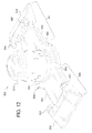
- FIG. 12 is a top perspective view of a further alternative embodiment of the lock out insert of the present disclosure.
- the present disclosure provides a set of different side bearings, each of which can be assembled using a common cage, a common cap, one of a plurality of different lock out inserts, and one of a plurality of different elastomer elements.
- Each different lock out insert includes a key that is differently dimensioned to correspond to an interior channel of a different elastomer element. While the present application describes various examples of side bearing components including different lock out inserts, different elastomer elements, a same cage, and a same cap, it should be appreciated that the present disclosure is not limited to these example side bearing components.
- FIGS. 5 , 6 , 7 A, 7 B, and 8 illustrate an example cage 500 and an example lock out insert 600 of one embodiment of the present disclosure. More specifically, cage 500 is configured to receive any one of a plurality of different lock out inserts.
- the cage 500 includes a base or base wall 506 having a bottom or first side 508 and a top or second side 510 .
- the cage 500 includes a side wall 512 integrally formed with the base 506 .
- the side wall 512 extends upwardly from the base 506 to form an element receiving area 704 (shown in FIG. 5 ).
- the based 506 defines a key opening 502 (shown in FIGS. 5 and 7B ).
- the base 506 and the side wall 512 define locking the tab receiving slots 504 A and 504 B (shown in FIGS. 5 and 7B ) configured to respectively receive locking tabs 612 and 618 of the lock out insert 600 as further described below.
- the cage 500 includes attachment feet 511 A and 511 B that respectively define mounting holes 505 A and 505 B used to connect the cage 500 directly to a bolster or to a bearing pad (such as the bearing pad 110 of FIG. 1 ) on a bolster.
- the side wall 512 of the cage 500 also defines cap receiving channels 507 A and 507 B configured to receive the cap side wall extensions of a cap 112 as discussed above and below.
- the bottom or first side 508 of the base 506 includes or defines a lock out insert receiving channel 702 as best illustrated in FIG. 7B .
- the channel 702 is recessed into the bottom or first side 508 of the base 506 to accommodate the lock out insert 600 (as best shown in FIG. 7A ).
- the lock out insert 600 is configured to be attached to the cage 500 such that a bottom side of the lock out insert 600 extends flush with the bottom side 508 of the base 506 (as best shown in FIG. 7A ), thereby causing the cage 500 to be level when attached to a bolster or bearing pad on a bolster.
- the lock out insert receiving channel 702 is configured based on the configuration of the body 602 and the arms 608 and 614 of the lock out insert 600 (which are further described below). However, it should be appreciated that the bottom of the lock out insert does not need to be flush with the bottom of the base of the cage in all embodiments of the present disclosure.
- the base 506 and the side wall 512 define the locking tab receiving slots 504 A and 504 B which each have a curvature partially defined by the side wall 512 .
- the locking tab receiving slots 504 A and 504 B are respectively configured to receive the locking tabs 612 and 618 of the lock out insert 600 as further discussed below.
- the base and the side wall can alternatively define additional or fewer locking tab receiving slots.
- the locking tab receiving slots may alternatively be defined only by the base or further alternatively only by the side wall.
- the locking tab receiving slots may be located in portions of the base which are interior from the side wall.
- the key opening 502 enables a key 620 of the lock out insert 600 to extend through the base 506 into the element receiving area 704 .
- the key opening 502 is dimensioned to enable keys of varying diameters on different lock out inserts to extend through the opening 502 . In this manner, the key opening 502 enables the same cage 500 to be used with different lock out inserts with different diameter keys.
- the dimensions of the example illustrated cage 500 are shown by the relation of dimensions and/or features of the side wall 512 and the base 506 . It should be appreciated that the dimensions and/or features of the side wall and/or the base may vary based on side bearing specifications. For example, the dimensions of the locking tab receiving slots may vary to accommodate different locking tab sizes and/or shapes. It should also be appreciated that the dimensions and/or shape of the key opening can vary to accommodate different key sizes and/or shapes. It should also be appreciated that in alternative embodiments, multiple key openings are formed in the base of the cage to accommodate lock out inserts with multiple keys.
- FIG. 6 shows a top perspective view of an example lock out insert 600 that is connectable to the cage 500 .
- the lock out insert 600 includes a body 602 having a first end 604 and a second end 606 .
- a first arm 608 is attached to the first end 604 .
- the first arm 608 includes an extension section 610 and a locking tab 612 .
- a second arm 614 is attached to the second end 606 of the body 602 .
- the second arm 614 includes an extension section 616 and a locking tab 618 .
- Extension section 610 is located between the first end 604 and the locking tab 612 .
- Extension section 616 is located between the second end 606 and the locking tab 614 .
- the extension sections 610 and 616 fit within the lock out insert receiving channel 702 of or defined by the base 506 of the cage 500 .
- the extension sections 610 and 616 provide structural support for the body 602 when the respective locking tabs 612 and 618 are positioned in and engaged with the base 506 and/or the side wall 512 of the cage 500 .
- the lock out insert includes only one arm or more than two arms.
- each of the locking tabs 612 and 618 securely attach the lock out insert 600 to the cage 500 by snapping into the respective locking tab receiving slots and contacting the base 506 and the side wall 512 .
- each of the locking tabs 612 and 618 respectively include curved walls 613 and 619 that respectively defined grooves 613 A (not shown) and 619 A configured to receive opposite edges of the base 506 .
- the locking tabs 612 and 618 are connected to the base 506 by causing the respective walls of the locking tabs that define the grooves to securely engage the edges and/or lips of the base 506 that define part of the locking tab receiving slots.
- the locking tabs may be alternatively shaped to engage and/or connect to other portions of the base 506 and/or the side wall 512 . It should also be appreciated that in other embodiments, the lock out insert does not snap fit or otherwise securely connect with the base, but rather is just positioned with the base of the cage when installed on the bolster.
- the illustrated configuration enables the locking tabs 612 and 618 to be respectively removed from the locking tab receiving slots 504 A and 504 B and disengaged from the base 506 .
- surfaces of the locking tabs 612 and 618 also engage the side wall 512 which defines the top of the respective slots 504 A and 504 B.
- the locking tabs 612 and 618 may alternatively be connected to the base 506 and/or the side wall 512 in other suitable manners such as by adhesive(s), mechanical fasteners, weld(s), and/or heat staking in accordance with the present disclosure.
- This illustrated embodiment of the lock out insert 600 also includes a key lip 622 and a cylindrical key 620 that tangentially extends from the key lip 622 and the body 602 of the lock out insert 600 .
- the key lip 622 has a diameter that corresponds to a diameter of the key opening 502 defined by the base 506 .
- the key 620 has a diameter that is smaller than the key opening 502 .
- the key lip 622 securely engages with the circular edge of the base 506 that defines the key opening 502 to provide support, alignment, and positioning for the key 620 , and to further provide the snap fit of the lock out insert to the base 506 .
- the present disclosure contemplates different diameter keys 620 with a common diameter key lip 622 so that different lock out inserts can be attached to the same cage 500 . It should also be appreciated that in other embodiments, the key lip 622 does not snap fit or otherwise securely connect with the base, but rather is just positioned with the base of the cage when installed on the bolster. It should also be appreciated that in other embodiments, the lock out insert does not include a key lip.
- FIGS. 7A and 7B show that in this illustrated embodiment, the lock out insert 600 is attached to the cage 500 by aligning the key 620 with the key opening 502 and pressing the insert 600 into the cage 500 so that the body 602 and arms 608 and 614 fit within the lock out insert receiving channel 702 .
- the locking tabs 612 and 618 engage the edge of base 602 and the side wall 512 that defines the corresponding locking tab receiving slots 504 A and 504 B.
- the body 602 and/or the arms 608 and 614 provide support for the key 620 by contacting the bottom or first side 508 of the base 506 in this illustrated embodiment.
- an elastomer element can be attached to the key 620 of that lock out insert.
- the diameter of the key 620 corresponds to a diameter of an interior channel of one of the elastomer elements (such as one of elements 114 A, 114 B, 114 C, and 114 D) that is to be engaged with the key 620 .
- the key 620 diameter is dimensioned so that the interior channel 210 of a corresponding element can accommodate and/or fit over the key 620 while having enough contact force on the inner cylindrical wall of the key 620 to attach and/or engage with the key 620 .
- the cylindrical outer side wall of the key 620 contacts the inner wall which defines the interior channel 210 to connect the key 620 to the element.
- the key 620 functions as a lock out that ensures only the element 114 with a correspondingly dimensioned interior channel 210 is paired with the appropriate lock out insert 600 during production of the side bearing.
- the key may be configured to not cause a direct contact with the inner wall(s) of the element, and that in further embodiments, the key may be configured to cause limited direct contact with the inner wall(s) of the element.
- one or more fastening mechanisms such as but not limited to one or more pins may be employed to maintain the element on the key of the lock out insert.
- the key 620 has a height that corresponds to a height of the interior channel 210 of the respective or matching elastomer element.
- the shape of the key 620 corresponds to a shape of the interior channel 210 of the elastomer element in the illustrated embodiment.
- both the interior channel and the key are cylindrically shaped.
- the key has a corresponding rectangular shape.
- differently rated elastomer elements may have differently shaped interior channels to provide additional lock out protection to ensure the appropriate key elastomer element combination is used.
- the lock out insert 600 including, for example, the body 602 , the arms 608 and 614 , the key 620 , and/or the key lip 622 can be made of various different suitable materials.
- the lock out insert is made from a high-density polyethylene.
- the lock out insert is made from a high-density polypropylene.
- the lock out insert is made from a cast or forged metal such as a cast aluminum.
- the example lock out insert can be made from certain combinations of materials, composite materials, or can be an impregnated material.
- different lock-out inserts may be made from different materials. It should also be appreciated that making different lock out inserts of such materials is substantially cheaper than making different cages as described above.
- each lock out insert can be made in any suitable manner.
- the lock out insert is manufactured using a conventional molding process.
- the lock out insert can be formed from alternative methods and that the employed manufacturing process may in part depend on the shape, size, and material of the lock out insert. Additionally, it should be appreciated that: (a) the material of the lock out insert; (b) the shape and configuration of the lock out insert including its height, width, and depth; and (c) the dimensions of the key can each be specifically selected based on the interior channel of a corresponding elastomer element.
- FIGS. 9A , 9 B, 9 C, and 9 D shows a set of example lock out inserts 600 A, 600 B, 600 C, and 600 D and corresponding example elastomer elements 114 A, 114 B, 114 C, and 114 D that can be used with the example cage 500 of FIGS. 5 , 7 , and 8 and the example cap 112 of FIGS. 1 , 2 , 3 , 4 A, 4 B, 4 C, and 4 D, 9 A, 9 B, 9 C, and 9 D to create different side bearings depending on the desired specifications of those side bearings.
- the lock out inserts 600 A, 600 B, 600 C, and 600 D each have the same configuration of the lock out insert 600 illustrated in FIGS. 6 , 7 , and 8 .
- the same cap 112 and the same cage 500 can be used with any of the different insert-elastomer element combinations as shown in FIGS. 9A , 9 B, 9 C, and 9 D, which significantly reduces the number of different cages that have to be manufactured and inventoried.
- each of the keys 620 A, 620 B, 620 C, and 620 D could have different shapes based on the shapes of the corresponding interior channels 210 A, 210 B, 210 C, and 210 D.
- the lock out insert 600 A includes the key 620 A with a diameter that corresponds to the diameter of the interior channel 210 A;
- the lock out insert 600 B includes the key 620 B with a diameter that corresponds to the diameter of the interior channel 210 B;
- the lock out insert 600 C includes the key 620 C with a diameter that corresponds to the diameter of the interior channel 210 C;
- the lock out insert 600 D includes the key 620 D with a diameter that corresponds to the diameter of the interior channel 210 D.
- the diameter of the key 620 A prevents the elements 114 B, 114 C, and 114 D from being attached to the lock out insert 620 A because the interior channels 210 B, 210 C, and 210 D are too narrow to accommodate (e.g., fit around) the key 620 A.
- FIGS. 9A , 9 B, 9 C, and 9 D show that each of the lock out inserts 600 A, 600 B, 600 C, and 600 D include the same size key lip 622 so that the inserts 600 A, 600 B, 600 C, and 600 D can each be attached to the base 506 of the cage 500 . Additionally, the example lock out inserts 600 A, 600 B, 600 C, and 600 D include suitable different identifiers used to determine which respective insert should be used with which of the elastomer elements to form the differently rated side bearings.
- the identifier indicates that the insert 600 A is to be installed within a SBXII-30 side bearing and/or associated with the SBXII-30 elastomer element 114 A.
- each of the different lock out inserts may have or be of different colors that identify which of the inserts (e.g., similarly colored inserts) are associated with which of the elastomer elements to form the differently rated side bearings.
- FIGS. 9A , 9 B, 9 C, and 9 D shows four combinations, it should be appreciated that other sets may include fewer or additional combinations.
- the example keys 620 A, 620 B, 620 C, and 620 D may be of alternative shape and/or may have additional key features such as tabs, fins, indentations, and grooves, (all not shown) that are associated with corresponding keyed features within the respective interior channels 210 A, 210 B, 210 C, and 210 D.
- the key of the lock out insert can be solid or hollowed out.
- This alternative lock out insert 800 (similar to lock out insert 600 described above) includes: (a) a body 802 having a first end 804 and a second end 806 ; (b) a first arm 808 attached to the first end 804 and including an extension section 810 and a locking tab 812 ; (c) a second arm 814 attached to the second end 806 of the body 802 and including an extension section 816 and a locking tab 818 ; (d) a key lip 822 extending from the body 802 ; and (e) a key 820 extending from the key lip 822 .
- the lock out insert 800 includes base attachers 830 and 832 respectively extending upwardly from the locking tabs 812 and 818 . These base attachers 830 and 832 are configured to engage the top surface 510 of the base 506 of the cage 500 as generally shown in FIG. 11 to hold the lock out insert 800 onto the cage. It should be appreciated that in this embodiment, the lock out insert 800 and in particular the arms 808 and 814 are suitably flexible to enable the arms to bend when the lock out insert 800 is attached to the cage and thus snapped into place such that the base attachers hold the lock out insert to the cage. It should also be appreciated that the base attachers can be somewhat flexible for flexing during attachment to the base.
- base attachers do not interfere with the positioning of the elastomer element. It should further be appreciated that in accordance with the present disclosures: (a) the shape of the base attachers may vary; (b) the position of the base attachers may vary; and (c) the quantity of baser attachers may vary.
- This alternative lock out insert 900 (similar to lock out insert 600 described above) includes: (a) a body 902 having a first end 904 and a second end 906 ; (b) a first arm 908 attached to the first end 904 and including an extension section 910 and a locking tab 912 ; (c) a second arm 914 attached to the second end 906 of the body 902 and including an extension section 916 and a locking tab 918 ; (d) a key lip 922 extending from the body 902 ; and (e) a key 920 extending from the key lip 922 .
- the lock out insert 900 includes base attachers 930 , 932 , 934 , and 936 respectively extending from the corners of locking tabs 912 and 918 . These base attachers 930 , 932 , 934 , and 936 are configured to engage the top surface 510 of the base 506 of the cage 500 to hold the lock out insert 900 onto the cage.
Landscapes
- Engineering & Computer Science (AREA)
- Mechanical Engineering (AREA)
- Rolling Contact Bearings (AREA)
Abstract
Description
Claims (24)
Priority Applications (4)
| Application Number | Priority Date | Filing Date | Title |
|---|---|---|---|
| US13/670,243 US8869710B2 (en) | 2011-12-12 | 2012-11-06 | Railroad car side bearing |
| PCT/US2012/068910 WO2013090244A1 (en) | 2011-12-12 | 2012-12-11 | Railroad car side bearing |
| MX2014007044A MX350111B (en) | 2011-12-12 | 2012-12-11 | Railroad car side bearing. |
| CA2857041A CA2857041C (en) | 2011-12-12 | 2012-12-11 | Railroad car side bearing |
Applications Claiming Priority (2)
| Application Number | Priority Date | Filing Date | Title |
|---|---|---|---|
| US201161569574P | 2011-12-12 | 2011-12-12 | |
| US13/670,243 US8869710B2 (en) | 2011-12-12 | 2012-11-06 | Railroad car side bearing |
Publications (2)
| Publication Number | Publication Date |
|---|---|
| US20130145956A1 US20130145956A1 (en) | 2013-06-13 |
| US8869710B2 true US8869710B2 (en) | 2014-10-28 |
Family
ID=48570819
Family Applications (1)
| Application Number | Title | Priority Date | Filing Date |
|---|---|---|---|
| US13/670,243 Active 2033-04-17 US8869710B2 (en) | 2011-12-12 | 2012-11-06 | Railroad car side bearing |
Country Status (4)
| Country | Link |
|---|---|
| US (1) | US8869710B2 (en) |
| CA (1) | CA2857041C (en) |
| MX (1) | MX350111B (en) |
| WO (1) | WO2013090244A1 (en) |
Families Citing this family (5)
| Publication number | Priority date | Publication date | Assignee | Title |
|---|---|---|---|---|
| DE102015016024B4 (en) * | 2014-12-17 | 2023-12-21 | Liebherr-Aerospace Lindenberg Gmbh | Spring system of a rail vehicle |
| CN112272634B (en) | 2018-04-27 | 2023-05-23 | 阿母斯替德铁路公司 | Railway truck assembly with friction assist bearing |
| RU2698261C1 (en) * | 2018-09-04 | 2019-08-23 | Александр Александрович Андреев | Side bearing |
| US11091179B2 (en) | 2018-11-01 | 2021-08-17 | Amsted Rail Company, Inc. | Rail car side bearing |
| US11613281B2 (en) * | 2020-10-26 | 2023-03-28 | Amsted Rail Company, Inc. | Railway truck assembly having compressible side bearings |
Citations (24)
| Publication number | Priority date | Publication date | Assignee | Title |
|---|---|---|---|---|
| US3707927A (en) | 1970-09-28 | 1973-01-02 | Standard Car Truck Co | Resilient truck side bearings |
| US3719152A (en) | 1969-06-12 | 1973-03-06 | Thrall Car Mfg Co | Railroad car with fluid side bearing antisway means |
| US3735711A (en) | 1971-07-16 | 1973-05-29 | Evans Prod Co | Elastomeric railway car side bearing |
| US3888555A (en) | 1972-08-23 | 1975-06-10 | Moss Jr John H Van | Elastomeric railway car side bearing |
| US3932005A (en) | 1974-05-10 | 1976-01-13 | Uniroyal Inc. | Elastomeric railway car with side bearing |
| US4103624A (en) | 1974-03-04 | 1978-08-01 | Acf Industries, Incorporated | Railway car truck side bearings |
| US4108080A (en) | 1975-04-29 | 1978-08-22 | Acf Industries, Incorporated | Railway car truck and side bearing assembly |
| US4567833A (en) | 1984-09-20 | 1986-02-04 | Holland Company | Composite constant contact side bearing for railroad cars |
| US4712487A (en) | 1985-05-28 | 1987-12-15 | Miner Enterprises, Inc. | Side bearing unit for railroad car, including method of making |
| US4793720A (en) | 1988-01-21 | 1988-12-27 | American Standard Inc. | Railway car resilient side bearing |
| US4924779A (en) | 1989-02-21 | 1990-05-15 | Thrall Car Manufacturing Company | Long-travel side bearing for an articulated railroad car |
| US5036774A (en) | 1989-02-21 | 1991-08-06 | Thrall Car Manufacturing Company | Long-travel side bearing for an articulated railroad car |
| US5046865A (en) | 1987-10-16 | 1991-09-10 | A. Stucki Company | Side bearing |
| US5682822A (en) | 1996-07-15 | 1997-11-04 | Sunderman; John R. | Railway car side bearing |
| US6092470A (en) | 1998-12-03 | 2000-07-25 | Miner Enterprises, Inc. | Railroad car side bearing with thermal insulator |
| US20030106456A1 (en) | 2001-07-19 | 2003-06-12 | Faryniak John G. | Railway truck side bearing |
| US6792871B2 (en) | 2002-11-07 | 2004-09-21 | Miner Enterprises, Inc. | Railroad car energy absorption apparatus |
| US20050087092A1 (en) | 2003-10-23 | 2005-04-28 | Mckisic Aubra D. | Modular base side bearing |
| WO2008043026A2 (en) | 2006-10-04 | 2008-04-10 | Cooper-Standard Automotive Inc. | Railcar side bearing assembly |
| US7527131B1 (en) | 2008-10-06 | 2009-05-05 | Amsted Rail Company, Inc. | Railway freight car truck |
| US7546807B2 (en) | 2006-07-19 | 2009-06-16 | Amsted Rail Company, Inc | Constant contact side bearing |
| US7549379B2 (en) | 2006-07-19 | 2009-06-23 | Amsted Rail Company, Inc | Railway freight car side bearing |
| US7802524B1 (en) | 2009-08-11 | 2010-09-28 | Wabtec Holding Corp. | Constant contact side bearing assembly with improved cap machining for a railcar |
| US8136457B2 (en) | 2009-08-13 | 2012-03-20 | Wabtec Corporation | Side bearing for a railroad car truck |
-
2012
- 2012-11-06 US US13/670,243 patent/US8869710B2/en active Active
- 2012-12-11 WO PCT/US2012/068910 patent/WO2013090244A1/en not_active Ceased
- 2012-12-11 MX MX2014007044A patent/MX350111B/en active IP Right Grant
- 2012-12-11 CA CA2857041A patent/CA2857041C/en active Active
Patent Citations (25)
| Publication number | Priority date | Publication date | Assignee | Title |
|---|---|---|---|---|
| US3719152A (en) | 1969-06-12 | 1973-03-06 | Thrall Car Mfg Co | Railroad car with fluid side bearing antisway means |
| US3707927A (en) | 1970-09-28 | 1973-01-02 | Standard Car Truck Co | Resilient truck side bearings |
| US3735711A (en) | 1971-07-16 | 1973-05-29 | Evans Prod Co | Elastomeric railway car side bearing |
| US3888555A (en) | 1972-08-23 | 1975-06-10 | Moss Jr John H Van | Elastomeric railway car side bearing |
| US4103624A (en) | 1974-03-04 | 1978-08-01 | Acf Industries, Incorporated | Railway car truck side bearings |
| US3932005A (en) | 1974-05-10 | 1976-01-13 | Uniroyal Inc. | Elastomeric railway car with side bearing |
| US4108080A (en) | 1975-04-29 | 1978-08-22 | Acf Industries, Incorporated | Railway car truck and side bearing assembly |
| US4567833A (en) | 1984-09-20 | 1986-02-04 | Holland Company | Composite constant contact side bearing for railroad cars |
| US4712487A (en) | 1985-05-28 | 1987-12-15 | Miner Enterprises, Inc. | Side bearing unit for railroad car, including method of making |
| US5046865A (en) | 1987-10-16 | 1991-09-10 | A. Stucki Company | Side bearing |
| US4793720A (en) | 1988-01-21 | 1988-12-27 | American Standard Inc. | Railway car resilient side bearing |
| US4924779A (en) | 1989-02-21 | 1990-05-15 | Thrall Car Manufacturing Company | Long-travel side bearing for an articulated railroad car |
| US5036774A (en) | 1989-02-21 | 1991-08-06 | Thrall Car Manufacturing Company | Long-travel side bearing for an articulated railroad car |
| US5682822A (en) | 1996-07-15 | 1997-11-04 | Sunderman; John R. | Railway car side bearing |
| US6092470A (en) | 1998-12-03 | 2000-07-25 | Miner Enterprises, Inc. | Railroad car side bearing with thermal insulator |
| US20030106456A1 (en) | 2001-07-19 | 2003-06-12 | Faryniak John G. | Railway truck side bearing |
| US6792871B2 (en) | 2002-11-07 | 2004-09-21 | Miner Enterprises, Inc. | Railroad car energy absorption apparatus |
| US20050087092A1 (en) | 2003-10-23 | 2005-04-28 | Mckisic Aubra D. | Modular base side bearing |
| US8534202B2 (en) * | 2003-10-23 | 2013-09-17 | A. Stucki Company | Modular base side bearing |
| US7546807B2 (en) | 2006-07-19 | 2009-06-16 | Amsted Rail Company, Inc | Constant contact side bearing |
| US7549379B2 (en) | 2006-07-19 | 2009-06-23 | Amsted Rail Company, Inc | Railway freight car side bearing |
| WO2008043026A2 (en) | 2006-10-04 | 2008-04-10 | Cooper-Standard Automotive Inc. | Railcar side bearing assembly |
| US7527131B1 (en) | 2008-10-06 | 2009-05-05 | Amsted Rail Company, Inc. | Railway freight car truck |
| US7802524B1 (en) | 2009-08-11 | 2010-09-28 | Wabtec Holding Corp. | Constant contact side bearing assembly with improved cap machining for a railcar |
| US8136457B2 (en) | 2009-08-13 | 2012-03-20 | Wabtec Corporation | Side bearing for a railroad car truck |
Non-Patent Citations (1)
| Title |
|---|
| International Search Report and Written Opinion from PCT Application No. PCT/US2012/088910, dated Mar. 28, 2013. |
Also Published As
| Publication number | Publication date |
|---|---|
| MX2014007044A (en) | 2015-01-22 |
| US20130145956A1 (en) | 2013-06-13 |
| CA2857041A1 (en) | 2013-06-20 |
| WO2013090244A1 (en) | 2013-06-20 |
| MX350111B (en) | 2017-08-28 |
| CA2857041C (en) | 2018-12-04 |
Similar Documents
| Publication | Publication Date | Title |
|---|---|---|
| US8869710B2 (en) | Railroad car side bearing | |
| US7966946B1 (en) | Railway truck pedestal bearing adapter | |
| US8939087B2 (en) | Modular base side bearing | |
| US8925466B2 (en) | Brake beam assembly for a railway car truck | |
| EP2123534A2 (en) | Railroad freight car sidebearing | |
| US20080035012A1 (en) | Railway freight car side bearing | |
| MX2014005127A (en) | Railroad car bearing adapter pad. | |
| US20050268813A1 (en) | Railway truck pedestal bearing adapter | |
| CA2364511A1 (en) | Improved friction shoe for freight car truck | |
| US8356558B2 (en) | Constant contact side bearing | |
| US11066085B2 (en) | Axle box suspension of railcar | |
| CA2736407C (en) | Brake beam wear liner | |
| CA2945288C (en) | Railway truck bolster wear liner | |
| CN103244588A (en) | Bogie of railway truck and rubber spring of axle box of bogie | |
| CN100445145C (en) | Conductive Gaskets in Rail Car Center Plate Assemblies | |
| KR101775235B1 (en) | Door roller | |
| CA2833127C (en) | High friction railroad car components with friction modifying inserts | |
| US20150096456A1 (en) | Railcar truck | |
| CN101219629A (en) | Guide roll with high-strength cross-member | |
| CA2816655C (en) | Railcar brake beam wear liner | |
| MX2013015428A (en) | Brake beam paddle caps. | |
| US20200231188A1 (en) | Railcar bogie frame and bogie including same | |
| AU2019283855B2 (en) | Railroad car truck with stabilizing transom | |
| US11904912B2 (en) | Break beam wear guide | |
| US20220297730A1 (en) | Railway truck with releasable bearing adapter |
Legal Events
| Date | Code | Title | Description |
|---|---|---|---|
| AS | Assignment |
Owner name: STANDARD CAR TRUCK COMPANY, ILLINOIS Free format text: ASSIGNMENT OF ASSIGNORS INTEREST;ASSIGNORS:SAMMARTINO, GIUSEPPE;PLEGGE, RICHARD W.;SIGNING DATES FROM 20120118 TO 20120119;REEL/FRAME:029289/0537 |
|
| STCF | Information on status: patent grant |
Free format text: PATENTED CASE |
|
| FEPP | Fee payment procedure |
Free format text: PAYOR NUMBER ASSIGNED (ORIGINAL EVENT CODE: ASPN); ENTITY STATUS OF PATENT OWNER: LARGE ENTITY |
|
| MAFP | Maintenance fee payment |
Free format text: PAYMENT OF MAINTENANCE FEE, 4TH YEAR, LARGE ENTITY (ORIGINAL EVENT CODE: M1551) Year of fee payment: 4 |
|
| AS | Assignment |
Owner name: TRANSPORTATION IP HOLDINGS, LLC, CONNECTICUT Free format text: ASSIGNMENT OF ASSIGNORS INTEREST;ASSIGNOR:STANDARD CAR TRUCK COMPANY;REEL/FRAME:059725/0207 Effective date: 20220101 |
|
| MAFP | Maintenance fee payment |
Free format text: PAYMENT OF MAINTENANCE FEE, 8TH YEAR, LARGE ENTITY (ORIGINAL EVENT CODE: M1552); ENTITY STATUS OF PATENT OWNER: LARGE ENTITY Year of fee payment: 8 |
|
| MAFP | Maintenance fee payment |
Free format text: PAYMENT OF MAINTENANCE FEE, 12TH YEAR, LARGE ENTITY (ORIGINAL EVENT CODE: M1553); ENTITY STATUS OF PATENT OWNER: LARGE ENTITY Year of fee payment: 12 |