US8861174B2 - Device and method for quick closing of an electric circuit and a use of the device - Google Patents
Device and method for quick closing of an electric circuit and a use of the device Download PDFInfo
- Publication number
- US8861174B2 US8861174B2 US14/071,002 US201314071002A US8861174B2 US 8861174 B2 US8861174 B2 US 8861174B2 US 201314071002 A US201314071002 A US 201314071002A US 8861174 B2 US8861174 B2 US 8861174B2
- Authority
- US
- United States
- Prior art keywords
- spark gap
- auxiliary
- nozzle
- main
- arc
- Prior art date
- Legal status (The legal status is an assumption and is not a legal conclusion. Google has not performed a legal analysis and makes no representation as to the accuracy of the status listed.)
- Active
Links
Images


Classifications
-
- H—ELECTRICITY
- H01—ELECTRIC ELEMENTS
- H01T—SPARK GAPS; OVERVOLTAGE ARRESTERS USING SPARK GAPS; SPARKING PLUGS; CORONA DEVICES; GENERATING IONS TO BE INTRODUCED INTO NON-ENCLOSED GASES
- H01T2/00—Spark gaps comprising auxiliary triggering means
- H01T2/02—Spark gaps comprising auxiliary triggering means comprising a trigger electrode or an auxiliary spark gap
-
- H—ELECTRICITY
- H05—ELECTRIC TECHNIQUES NOT OTHERWISE PROVIDED FOR
- H05H—PLASMA TECHNIQUE; PRODUCTION OF ACCELERATED ELECTRICALLY-CHARGED PARTICLES OR OF NEUTRONS; PRODUCTION OR ACCELERATION OF NEUTRAL MOLECULAR OR ATOMIC BEAMS
- H05H1/00—Generating plasma; Handling plasma
- H05H1/24—Generating plasma
- H05H1/48—Generating plasma using an arc
- H05H1/50—Generating plasma using an arc and using applied magnetic fields, e.g. for focusing or rotating the arc
Definitions
- the present invention in a first aspect relates to a device for quick closing an electric circuit, said device comprising a main spark gap provided with a first and a second main electrode and a triggering device, said triggering device comprising an auxiliary spark gap provided with a first and a second auxiliary electrodes for igniting an arc in the main spark gap, said auxiliary electrodes being shielded from said main spark gap by a shielding unit having channel means extending therethrough from an auxiliary spark gap facing side to a main spark gap facing side.
- the invention in a second aspect relates to a method for quickly closing an electric circuit by generating an arc between a first and a second main electrode of a main spark gap with the aid of a triggering device, wherein, when necessary, an arc is generated between a first and a second auxiliary electrode in an auxiliary spark gap associated with the triggering device, whereby an arc in the main spark gap is ignited with the aid of the arc in the auxiliary spark gap and the auxiliary spark gap is shielded from the main spark gap by a shielding unit having channel means extending therethrough from an auxiliary spark gap facing side to a main spark gap facing side.
- the invention relates to a use of the invented device.
- Series capacitors are used in electric power lines, primarily for increasing the transmission capability of a power line.
- Such series capacitor equipment comprises a capacitor bank that is connected to the power line and is traversed by the current of the power line. The voltage across such a series capacitor becomes proportional to the current in the power line, and in case of an over current in the power line, for example caused by a short circuit in the power network, an overvoltage arises across the series capacitor.
- the reason for this is that the mode of operation is based on the auxiliary spark gap substantially serving to ionize the air between the main electrodes. The ionization facilitates the formation of an arc between these; however, it assumes that the voltage is sufficient for a flashover to arise.
- the voltage across the main spark gap must amount to at least some 10 kV. This limits the possibilities of application.
- each auxiliary electrode is provided with guide rails designed such that the arc, via the guide rails and under the influence of the generated inherent magnetic field, moves into the main electrode gap, each of the two guide rails having a length that is larger than the width of the auxiliary spark gap, and which auxiliary electrodes are arranged such that they are protected from the effect of plasma formed in the main spark gap and whereby a hermetic enclosure encloses the main spark gap and the auxiliary spark gap.
- the generation of the arc in the main spark gap is achieved with that device in a way that is fundamentally physically different from what is achieved with conventional technique.
- the arc in the main spark gap is achieved by an igniting spark from the auxiliary spark gap ionizing the air between the main electrodes so that a flashover arises therebetween, which presupposes a very high voltage therebetween.
- the generation of the arc in the main spark gap is not correspondingly dependent on such ionization.
- the guide rails result in the arc in the auxiliary spark gap, by the inherent magnetic forces that arose around the arc, being brought to successfully move inwards towards the main spark gap so that gradually the arc is established between the electrodes of the main spark gap.
- the function of the spark gap will be relatively insensitive to the variation of its width. In this way, the spark gap need not be reconditioned after a discharge.
- the spark gap may thus be activated hundreds of times without any requirement for intermediate service. Further, the spark gap may be used for new functions where no high voltage arises when the spark gap is to be activated. Further, the spark gap is insensitive to the external environment, such as moisture, ice, snow, dirt and insects. Since the auxiliary electrodes are protected from the effect of plasma formed in the main spark gap, the risk that the arc in the main spark gap may damage the auxiliary electrodes is avoided.
- An object of the present invention is to further improve a device of the kind in question.
- a device of the kind initially specified includes the specific features that the device further includes a nozzle with a first end being most close to the auxiliary spark gap and a second end most close to the main spark gap, which first end has an inlet opening that is in connection with said channel means.
- the nozzle creates a collected arc plasma that will be more directed towards the main spark gap than what can be achieved with known technique, e.g. such as in the above mentioned WO 03/096502.
- the strong concentration of the plasma jet increases the effectiveness of the triggering device and leads to a very precise operation and shorter trigging time. A trigging time less than 0.5 ms can easily be achieved with the nozzle.
- the voltage required across the main spark gap for forming an arc can be further reduced by the presence of the nozzle.
- the nozzle at least partly is arranged in said channel means.
- At least a part of the nozzle is formed by channel walls of the channel means.
- the integration of the nozzle and the shielding unit also in this respect provides a simple way of attaining the nozzle effect, where the channel means provides a part thereof.
- a nozzle head portion is provided on the main spark facing side of the shielding unit, and the nozzle extends at least partly through the nozzle head portion.
- a part of the nozzle thereby can be located in a part with smaller dimensions than what is required for the shielding unit.
- the space thus saved is advantageous with regards to the location of the outlet opening of the nozzle in relation to the main spark gap.
- the shielding unit, the nozzle head portion and the nozzle are made in the same material in one single piece.
- the interior of the nozzle is converging from the inlet opening to the outlet opening.
- a converging nozzle results in that the travelling arc or plasma jet will be more focused such that it enhances the effect of igniting the arc in the main gap.
- the nozzle converges continuously. If the interior cross section of the nozzle is square or rectangular it can converge either in that only two of the opposite sides converge or all four. Should the cross section be circular or oval, the shape may be conical or conical-like respectively.
- the outlet opening has an elongated shape.
- the outlet opening thus has a basically rectangular shape, but it is preferred that the corners are rounded. Thereby the complete short sides may be shaped as circular arcs. Preferably also the inlet opening has a corresponding shape.
- the interior shape of the nozzle is elongated in any section thereof perpendicular to the longitudinal extension of the nozzle.
- the material of the nozzle is a polymer.
- Suitable polymers are polyoxybenzylmethylenglycolanhydride (Bakelite), polyester, polyimide and polytetrafluorethylene (Teflon).
- the material of the nozzle is polytetrafluorethylene.
- polytetrafluorethylene is optimal for meeting the above demands.
- polytetrafluorethylene has shown to have a high ability to withstand this wear. A high number of operations thus can be performed without too much widening of the outlet opening.
- At least one of the main electrodes is ring-shaped and the nozzle is arranged centrally with respect to the ring-shaped electrode.
- the distance between the electrodes can be reduced such that this location will be optimal with regards to create an arc in the main spark gap.
- the ring-shape of the electrodes thereby contributes to further reduce the trigging time.
- each auxiliary electrode is provided with a guide rail designed such that the arc, via the guide rails and under the influence of the generated inherent magnetic field, moves towards the shielding wall unit.
- the invention also relates to a series capacitor that includes an overvoltage protection apparatus provided with a device according to the present invention, in particular to any of the above described embodiments thereof.
- the invented overvoltage apparatus implies that the advantages of the invented device are used in a field where these advantages are made use of to a large extent.
- a method of the kind introductionally specified further includes the specific steps of arranging a nozzle with a first end being most close to the auxiliary spark gap and a second end most close to the main spark gap, arranging an inlet opening at the first end, connecting the inlet opening to said channel means and arranging an outlet opening at the second end, and thereby directing an arc from the auxiliary spark gap to move to the main spark gap via the nozzle.
- the object is achieved in that the invented device is used for quickly closing an electric high voltage circuit.
- the device is used to protect a series capacitor from overvoltage.
- FIG. 1 is a side view of an electrode and its supporting structure according to the present invention.
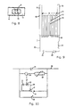
- FIG. 2 is a first diametrical section through the upper part of FIG. 1 .
- FIG. 3 is a second diametrical section through the upper part of FIG. 1 , orthogonal to the section of FIG. 2 .
- FIG. 4 is a perspective view of a detail in FIGS. 2 and 3 .
- FIG. 5 is a first section through the detail of FIG. 4 .
- FIG. 6 is a second section through the detail of FIG. 4 .
- FIG. 7 is a top end view of the detail in FIG. 4 .
- FIG. 8 is a bottom end view of the detail in FIG. 4 .
- FIG. 9 is a schematic illustration of the auxiliary spark gap according to the invention.
- FIG. 10 illustrates a series capacitor provided with an over voltage protection device according to the present invention.
- FIG. 1 in a side view illustrates one of the main electrodes 1 in a device according to the invention.
- the electrode 1 is mounted on a support structure 2 and cooperates with a second electrode (not shown) forming a main spark gap A between each other.
- the electrode 1 has the shape of a circular ring and may be of cupper.
- the device is located within a hermetic enclosure (not shown).
- FIGS. 1 and 2 of that disclosure Specific reference is made to FIGS. 1 and 2 of that disclosure and the corresponding parts of the description regarding an example how the triggering device may be constructed, how the auxiliary spark gap can be constructed and how the arc in the auxiliary spark gap functions to create an arc in the main spark gap.
- the focus of the present invention is related to the construction of the triggering device in the region between the shielding device and the main spark gap.
- FIG. 1 The upper part of FIG. 1 is illustrated in FIGS. 2 and 3 in two diametrical sections which are orthogonal to each other.
- the triggering device 3 has a shell enclosing a triggering circuit and a pair of auxiliary electrodes forming an auxiliary spark gap. This device will be explained further below in connection with FIG. 9 .
- the triggering device 3 is covered by a shielding unit 4 , through which a central channel means extends.
- a shielding unit 4 On top of the shielding unit 4 there is a nozzle head portion 5 .
- the inside of the nozzle head portion 5 and the upper part of the channel means within the shielding unit 4 form a nozzle 6 , through which the arc from the auxiliary spark gap in the triggering device moves towards the main spark gap A.
- the arrangement of the nozzle 6 in relation to the shielding unit 4 and the nozzle head portion 5 is explained more in detail with reference to FIG. 4-8 .
- the shielding unit 4 is substantially box shaped with a rectangular cross section perpendicular to the longitudinal extension of the nozzle 6 .
- the shielding unit 4 has an auxiliary spark gap facing side 11 directed towards the triggering device and a main spark facing side 12 directed towards the main spark gap A.
- the nozzle head portion 5 is mounted on the main spark facing side 11 of the shielding unit 4 and has circular cylindrical shape.
- the shielding unit 4 and the nozzle head portion 5 are in this example made as one piece and the material is polytetrafluorethylene.
- the outlet opening 8 of the nozzle 6 can be seen.
- the outlet opening 8 has an elongated shape.
- FIG. 5 is a section through FIG. 4 taken along a central plane in parallel with the large sides of the shielding unit 4 .
- the channel means through the shielding unit 4 has a lower wide part 10 close to the auxiliary spark gap and an upper more narrow part 9 close to the nozzle 6 .
- Each of these parts have parallel straight walls.
- the nozzle 6 connects to the upper end of the narrow part 9 of the channel means.
- the nozzle 6 is in this section converging from its inlet opening 7 connected to part 9 to its outlet opening 8 . As can be seen the nozzle in this example extends partly through the nozzle head portion 5 and partly through the upper part of the shielding unit 4 .
- FIG. 6 is a section orthogonal to that of FIG. 5 .
- the channel means 9 , 10 and the nozzle 6 have the same width and straight parallel walls.
- the top end and the bottom end of the component in FIG. 4 is shown in a respective end view in FIGS. 7 and 8 , respectively.
- the shielding unit 4 has the dimensions 40 ⁇ 28 ⁇ 20 mm.
- the nozzle head portion has a height of 11 mm and a diameter of 18 mm.
- the lower part 10 of the channel means has a depth of 11 mm and a cross section of 22 ⁇ 10 mm, the upper part a depth of 12 mm and a cross section of 8 ⁇ 10 mm.
- the converging nozzle 6 has a length of 16 mm.
- the inlet opening 7 of the nozzle has a length of 10 mm and a width of 8 mm and the outlet opening 8 a length of 10 mm and a width of 4 mm.
- the auxiliary spark gap B is illustrated schematically in FIG. 9 . It has a first auxiliary electrode 13 and a second auxiliary electrode 14 . Each of these electrodes has an elongation forming a respective guiding rail 15 , 16 .
- the guiding rails 15 , 16 have the function to lead the arc generated in the auxiliary spark gap B towards the shielding unit 4 , through the same and through the nozzle 6 to reach the main spark gap for generating an arc therein.
- the triggering circuit 20 for the auxiliary electrodes 13 , 14 has a capacitor bank 21 with one side connected to the first auxiliary electrode 13 and to ground. The other side is via a coil 23 and a normally open closer 22 , in this example in the form of a thyristor, connected to the second auxiliary electrode 14 .
- auxiliary electrodes 13 , 14 Upon a command the closer 22 closes in order to trigger an arc in the auxiliary spark gap B.
- auxiliary electrodes 13 , 14 Between the auxiliary electrodes 13 , 14 a number of subelectrodes 17 are arranged, which may be of cupper.
- a layer of an insulating material 18 is provided between each pair of subelectrodes 17 and between each auxiliary electrode 13 , 14 and the respective closest subelectrode.
- a resistor 19 connects each pair of subelectrodes to each other and each auxiliary electrode 13 , 14 to the nearest subelectrode.
- FIG. 10 shows a diagram where the device is applied as overvoltage protection device for a series capacitor.
- an overvoltage protection device comprising a varistor 32 , a main spark gap A and a mechanical contact device 33 , these three components being connected in parallel.
- a current-measuring device 34 is arranged in series with the varistor.
- an overvoltage arises across the capacitor 31 .
- the current through the varistor 32 is measured with the current-measuring device 34 .
- the measurement is integrated for a period of a few ms to some 20 or 30 ms, and the volume of energy measured constitutes a criterion as to whether the overvoltage protection device is to be activated or not.
- the threshold value, at which activation occurs may be of the order of magnitude of some 20 or 30 MJ.
- the current-measuring device 34 thus defines when there is a need to generate an arc.
- the current-measuring device sends a signal to the closer 22 .
- the contact device 33 is activated to close.
Landscapes
- Physics & Mathematics (AREA)
- Engineering & Computer Science (AREA)
- Plasma & Fusion (AREA)
- Spectroscopy & Molecular Physics (AREA)
- Plasma Technology (AREA)
- Circuit Breakers (AREA)
- Portable Nailing Machines And Staplers (AREA)
Abstract
Description
Claims (17)
Applications Claiming Priority (4)
| Application Number | Priority Date | Filing Date | Title |
|---|---|---|---|
| EP11164925 | 2011-05-05 | ||
| EP11164925.7 | 2011-05-05 | ||
| EP11164925.7A EP2521228B1 (en) | 2011-05-05 | 2011-05-05 | Device and method for quick closing of an electric circuit and a use of the device |
| PCT/EP2012/058179 WO2012150313A1 (en) | 2011-05-05 | 2012-05-04 | Device and method for quick closing of an electric circuit and a use of the device |
Related Parent Applications (1)
| Application Number | Title | Priority Date | Filing Date |
|---|---|---|---|
| PCT/EP2012/058179 Continuation WO2012150313A1 (en) | 2011-05-05 | 2012-05-04 | Device and method for quick closing of an electric circuit and a use of the device |
Publications (2)
| Publication Number | Publication Date |
|---|---|
| US20140055035A1 US20140055035A1 (en) | 2014-02-27 |
| US8861174B2 true US8861174B2 (en) | 2014-10-14 |
Family
ID=46025734
Family Applications (1)
| Application Number | Title | Priority Date | Filing Date |
|---|---|---|---|
| US14/071,002 Active US8861174B2 (en) | 2011-05-05 | 2013-11-04 | Device and method for quick closing of an electric circuit and a use of the device |
Country Status (9)
| Country | Link |
|---|---|
| US (1) | US8861174B2 (en) |
| EP (1) | EP2521228B1 (en) |
| CN (2) | CN202282550U (en) |
| AR (1) | AR086251A1 (en) |
| BR (1) | BR112013028114B1 (en) |
| CA (1) | CA2835189C (en) |
| MX (1) | MX2013012845A (en) |
| RU (1) | RU2553450C1 (en) |
| WO (1) | WO2012150313A1 (en) |
Families Citing this family (3)
| Publication number | Priority date | Publication date | Assignee | Title |
|---|---|---|---|---|
| EP2521228B1 (en) * | 2011-05-05 | 2014-01-01 | ABB Research Ltd. | Device and method for quick closing of an electric circuit and a use of the device |
| US10718880B2 (en) * | 2018-11-29 | 2020-07-21 | Schlumberger Technology Corporation | High-voltage protection and shielding within downhole tools |
| CN115243440B (en) * | 2022-08-15 | 2024-12-03 | 中国工程物理研究院流体物理研究所 | Auxiliary triggering novel plasma focus device |
Citations (12)
| Publication number | Priority date | Publication date | Assignee | Title |
|---|---|---|---|---|
| US3725729A (en) | 1971-10-29 | 1973-04-03 | Us Army | Electrical crowbar system with novel triggered spark gap devices |
| US4625254A (en) | 1983-06-17 | 1986-11-25 | Asea Aktiebolag | Voltage trigger means for a series capacitor protector |
| US4652963A (en) | 1984-03-07 | 1987-03-24 | Asea Aktiebolag | Series capacitor equipment |
| US4703385A (en) | 1985-05-13 | 1987-10-27 | Asea Aktiebolag | Protective circuit for series capacitor banks |
| US4860156A (en) | 1987-09-04 | 1989-08-22 | Asea Brown Boveri Ab | Overvoltage protective circuit |
| US5325259A (en) | 1989-12-22 | 1994-06-28 | Asea Brown Boveri Ab | Overvoltage protection for series capacitor equipment |
| US5893985A (en) | 1997-03-14 | 1999-04-13 | The Lincoln Electric Company | Plasma arc torch |
| WO2003096502A1 (en) | 2002-05-13 | 2003-11-20 | Abb Ab | Device and method for triggering a spark gap |
| US6700091B2 (en) | 2002-02-26 | 2004-03-02 | Thermal Dynamics Corporation | Plasma arc torch trigger system |
| US20080253040A1 (en) | 2007-04-16 | 2008-10-16 | Thangavelu Asokan | Ablative Plasma Gun |
| US20090134129A1 (en) | 2007-11-27 | 2009-05-28 | General Electric Company | Ablative plasma gun apparatus and system |
| US8102635B2 (en) * | 2005-07-01 | 2012-01-24 | Alstom Grid Oy | Method and arrangement for triggering a series spark gap |
Family Cites Families (9)
| Publication number | Priority date | Publication date | Assignee | Title |
|---|---|---|---|---|
| US2400457A (en) * | 1941-12-19 | 1946-05-14 | Vickers Electrical Co Ltd | Spark gap electrical apparatus |
| US2508954A (en) * | 1943-02-03 | 1950-05-23 | Merlin Gerin | Electric discharge device with auxiliary electrode |
| SU587544A1 (en) * | 1976-05-07 | 1978-01-05 | Научно-Исследовательский Институт Ядерной Физики,Электроники И Автоматики При Томском Политехническом Институте Им. С.М.Кирова | Controllable discharger |
| USH756H (en) | 1988-07-19 | 1990-03-06 | The United States Of America As Represented By The United States Department Of Energy | Radiation hard vacuum switch |
| SU1640765A1 (en) * | 1988-10-14 | 1991-04-07 | Московский энергетический институт | Gas-filled arrester |
| SE9702335D0 (en) * | 1997-06-18 | 1997-06-18 | Asea Brown Boveri | Current limiting device and protection against faults in a current |
| DE102004002581B4 (en) * | 2004-01-13 | 2005-11-10 | Siemens Ag | Spark gap with optically ignited power semiconductor component |
| FR2904893B1 (en) * | 2006-08-11 | 2008-10-10 | Soule Prot Surtensions Sa | TWO ELECTRODES PRIMER DEVICE FOR ECLATOR AND CORRESPONDING METHODS |
| EP2521228B1 (en) * | 2011-05-05 | 2014-01-01 | ABB Research Ltd. | Device and method for quick closing of an electric circuit and a use of the device |
-
2011
- 2011-05-05 EP EP11164925.7A patent/EP2521228B1/en active Active
- 2011-05-25 CN CN2011201764476U patent/CN202282550U/en not_active Expired - Lifetime
- 2011-05-25 CN CN201110148176.8A patent/CN102769253B/en active Active
-
2012
- 2012-05-03 AR ARP120101553A patent/AR086251A1/en not_active Application Discontinuation
- 2012-05-04 RU RU2013153886/07A patent/RU2553450C1/en active
- 2012-05-04 BR BR112013028114-6A patent/BR112013028114B1/en active IP Right Grant
- 2012-05-04 MX MX2013012845A patent/MX2013012845A/en active IP Right Grant
- 2012-05-04 CA CA2835189A patent/CA2835189C/en active Active
- 2012-05-04 WO PCT/EP2012/058179 patent/WO2012150313A1/en not_active Ceased
-
2013
- 2013-11-04 US US14/071,002 patent/US8861174B2/en active Active
Patent Citations (13)
| Publication number | Priority date | Publication date | Assignee | Title |
|---|---|---|---|---|
| US3725729A (en) | 1971-10-29 | 1973-04-03 | Us Army | Electrical crowbar system with novel triggered spark gap devices |
| US4625254A (en) | 1983-06-17 | 1986-11-25 | Asea Aktiebolag | Voltage trigger means for a series capacitor protector |
| US4652963A (en) | 1984-03-07 | 1987-03-24 | Asea Aktiebolag | Series capacitor equipment |
| US4703385A (en) | 1985-05-13 | 1987-10-27 | Asea Aktiebolag | Protective circuit for series capacitor banks |
| US4860156A (en) | 1987-09-04 | 1989-08-22 | Asea Brown Boveri Ab | Overvoltage protective circuit |
| US5325259A (en) | 1989-12-22 | 1994-06-28 | Asea Brown Boveri Ab | Overvoltage protection for series capacitor equipment |
| US5893985A (en) | 1997-03-14 | 1999-04-13 | The Lincoln Electric Company | Plasma arc torch |
| US6700091B2 (en) | 2002-02-26 | 2004-03-02 | Thermal Dynamics Corporation | Plasma arc torch trigger system |
| WO2003096502A1 (en) | 2002-05-13 | 2003-11-20 | Abb Ab | Device and method for triggering a spark gap |
| US7295416B2 (en) * | 2002-05-13 | 2007-11-13 | Abb Ab | Device and method for triggering a spark gap |
| US8102635B2 (en) * | 2005-07-01 | 2012-01-24 | Alstom Grid Oy | Method and arrangement for triggering a series spark gap |
| US20080253040A1 (en) | 2007-04-16 | 2008-10-16 | Thangavelu Asokan | Ablative Plasma Gun |
| US20090134129A1 (en) | 2007-11-27 | 2009-05-28 | General Electric Company | Ablative plasma gun apparatus and system |
Non-Patent Citations (2)
| Title |
|---|
| European Search Report Application No. EP 11 16 4925 Completed: Sep. 12, 2011; Mailing Date: Sep. 21, 2011 4 pages. |
| International Search Report & Written Opinion of the International Searching Authority Application No. PCT/EP2012/058179 Completed: May 23, 2013; Mailing Date: May 31, 2012 8 pages. |
Also Published As
| Publication number | Publication date |
|---|---|
| US20140055035A1 (en) | 2014-02-27 |
| AR086251A1 (en) | 2013-11-27 |
| EP2521228A1 (en) | 2012-11-07 |
| CA2835189C (en) | 2016-06-28 |
| CN102769253B (en) | 2016-06-29 |
| WO2012150313A1 (en) | 2012-11-08 |
| BR112013028114B1 (en) | 2021-02-02 |
| BR112013028114A2 (en) | 2016-12-27 |
| CN102769253A (en) | 2012-11-07 |
| CA2835189A1 (en) | 2012-11-08 |
| CN202282550U (en) | 2012-06-20 |
| MX2013012845A (en) | 2013-12-02 |
| RU2553450C1 (en) | 2015-06-20 |
| EP2521228B1 (en) | 2014-01-01 |
Similar Documents
| Publication | Publication Date | Title |
|---|---|---|
| US11038347B2 (en) | Overvoltage protection for power systems | |
| US8618435B2 (en) | Ablative plasma gun | |
| CN102202455B (en) | Plasma generation apparatus | |
| US8861174B2 (en) | Device and method for quick closing of an electric circuit and a use of the device | |
| CN102404928B (en) | For the equipment of extinguishing arc and system and assembly method | |
| EP1504507B1 (en) | Device and method for triggering a spark gap | |
| US20110248002A1 (en) | Plasma generation apparatus | |
| CN104023462B (en) | System and device for extinguishing arc | |
| KR200429336Y1 (en) | Discharge device for wide area lightning rod |
Legal Events
| Date | Code | Title | Description |
|---|---|---|---|
| FEPP | Fee payment procedure |
Free format text: PAYOR NUMBER ASSIGNED (ORIGINAL EVENT CODE: ASPN); ENTITY STATUS OF PATENT OWNER: LARGE ENTITY |
|
| AS | Assignment |
Owner name: ABB RESEARCH LTD., SWITZERLAND Free format text: ASSIGNMENT OF ASSIGNORS INTEREST;ASSIGNORS:JEPPSSON, OLA;PAULSSON, LARS;SIGNING DATES FROM 20131011 TO 20131022;REEL/FRAME:031553/0321 |
|
| STCF | Information on status: patent grant |
Free format text: PATENTED CASE |
|
| MAFP | Maintenance fee payment |
Free format text: PAYMENT OF MAINTENANCE FEE, 4TH YEAR, LARGE ENTITY (ORIGINAL EVENT CODE: M1551) Year of fee payment: 4 |
|
| AS | Assignment |
Owner name: ABB SCHWEIZ AG, SWITZERLAND Free format text: MERGER;ASSIGNOR:ABB RESEARCH LTD.;REEL/FRAME:051419/0309 Effective date: 20190416 |
|
| AS | Assignment |
Owner name: ABB POWER GRIDS SWITZERLAND AG, SWITZERLAND Free format text: ASSIGNMENT OF ASSIGNORS INTEREST;ASSIGNOR:ABB SCHWEIZ AG;REEL/FRAME:052916/0001 Effective date: 20191025 |
|
| AS | Assignment |
Owner name: HITACHI ENERGY SWITZERLAND AG, SWITZERLAND Free format text: CHANGE OF NAME;ASSIGNOR:ABB POWER GRIDS SWITZERLAND AG;REEL/FRAME:058666/0540 Effective date: 20211006 |
|
| MAFP | Maintenance fee payment |
Free format text: PAYMENT OF MAINTENANCE FEE, 8TH YEAR, LARGE ENTITY (ORIGINAL EVENT CODE: M1552); ENTITY STATUS OF PATENT OWNER: LARGE ENTITY Year of fee payment: 8 |
|
| AS | Assignment |
Owner name: HITACHI ENERGY LTD, SWITZERLAND Free format text: MERGER;ASSIGNOR:HITACHI ENERGY SWITZERLAND AG;REEL/FRAME:065549/0576 Effective date: 20231002 |
|
| MAFP | Maintenance fee payment |
Free format text: PAYMENT OF MAINTENANCE FEE, 12TH YEAR, LARGE ENTITY (ORIGINAL EVENT CODE: M1553); ENTITY STATUS OF PATENT OWNER: LARGE ENTITY Year of fee payment: 12 |