US8856477B1 - Networked raid in a virtualized cluster - Google Patents
Networked raid in a virtualized cluster Download PDFInfo
- Publication number
- US8856477B1 US8856477B1 US13/681,692 US201213681692A US8856477B1 US 8856477 B1 US8856477 B1 US 8856477B1 US 201213681692 A US201213681692 A US 201213681692A US 8856477 B1 US8856477 B1 US 8856477B1
- Authority
- US
- United States
- Prior art keywords
- tier
- storage
- data
- cluster
- zone
- Prior art date
- Legal status (The legal status is an assumption and is not a legal conclusion. Google has not performed a legal analysis and makes no representation as to the accuracy of the status listed.)
- Active
Links
Images


Classifications
-
- G—PHYSICS
- G06—COMPUTING OR CALCULATING; COUNTING
- G06F—ELECTRIC DIGITAL DATA PROCESSING
- G06F3/00—Input arrangements for transferring data to be processed into a form capable of being handled by the computer; Output arrangements for transferring data from processing unit to output unit, e.g. interface arrangements
- G06F3/06—Digital input from, or digital output to, record carriers, e.g. RAID, emulated record carriers or networked record carriers
- G06F3/0601—Interfaces specially adapted for storage systems
- G06F3/0668—Interfaces specially adapted for storage systems adopting a particular infrastructure
- G06F3/0671—In-line storage system
- G06F3/0683—Plurality of storage devices
- G06F3/0689—Disk arrays, e.g. RAID, JBOD
-
- G—PHYSICS
- G06—COMPUTING OR CALCULATING; COUNTING
- G06F—ELECTRIC DIGITAL DATA PROCESSING
- G06F3/00—Input arrangements for transferring data to be processed into a form capable of being handled by the computer; Output arrangements for transferring data from processing unit to output unit, e.g. interface arrangements
- G06F3/06—Digital input from, or digital output to, record carriers, e.g. RAID, emulated record carriers or networked record carriers
- G06F3/0601—Interfaces specially adapted for storage systems
- G06F3/0602—Interfaces specially adapted for storage systems specifically adapted to achieve a particular effect
- G06F3/0604—Improving or facilitating administration, e.g. storage management
- G06F3/0607—Improving or facilitating administration, e.g. storage management by facilitating the process of upgrading existing storage systems, e.g. for improving compatibility between host and storage device
-
- G—PHYSICS
- G06—COMPUTING OR CALCULATING; COUNTING
- G06F—ELECTRIC DIGITAL DATA PROCESSING
- G06F11/00—Error detection; Error correction; Monitoring
- G06F11/07—Responding to the occurrence of a fault, e.g. fault tolerance
- G06F11/14—Error detection or correction of the data by redundancy in operations
- G06F11/1446—Point-in-time backing up or restoration of persistent data
- G06F11/1458—Management of the backup or restore process
- G06F11/1464—Management of the backup or restore process for networked environments
-
- G—PHYSICS
- G06—COMPUTING OR CALCULATING; COUNTING
- G06F—ELECTRIC DIGITAL DATA PROCESSING
- G06F3/00—Input arrangements for transferring data to be processed into a form capable of being handled by the computer; Output arrangements for transferring data from processing unit to output unit, e.g. interface arrangements
- G06F3/06—Digital input from, or digital output to, record carriers, e.g. RAID, emulated record carriers or networked record carriers
- G06F3/0601—Interfaces specially adapted for storage systems
- G06F3/0602—Interfaces specially adapted for storage systems specifically adapted to achieve a particular effect
- G06F3/0614—Improving the reliability of storage systems
- G06F3/0617—Improving the reliability of storage systems in relation to availability
-
- G—PHYSICS
- G06—COMPUTING OR CALCULATING; COUNTING
- G06F—ELECTRIC DIGITAL DATA PROCESSING
- G06F3/00—Input arrangements for transferring data to be processed into a form capable of being handled by the computer; Output arrangements for transferring data from processing unit to output unit, e.g. interface arrangements
- G06F3/06—Digital input from, or digital output to, record carriers, e.g. RAID, emulated record carriers or networked record carriers
- G06F3/0601—Interfaces specially adapted for storage systems
- G06F3/0628—Interfaces specially adapted for storage systems making use of a particular technique
- G06F3/0646—Horizontal data movement in storage systems, i.e. moving data in between storage devices or systems
- G06F3/0647—Migration mechanisms
- G06F3/0649—Lifecycle management
-
- G—PHYSICS
- G06—COMPUTING OR CALCULATING; COUNTING
- G06F—ELECTRIC DIGITAL DATA PROCESSING
- G06F3/00—Input arrangements for transferring data to be processed into a form capable of being handled by the computer; Output arrangements for transferring data from processing unit to output unit, e.g. interface arrangements
- G06F3/06—Digital input from, or digital output to, record carriers, e.g. RAID, emulated record carriers or networked record carriers
- G06F3/0601—Interfaces specially adapted for storage systems
- G06F3/0628—Interfaces specially adapted for storage systems making use of a particular technique
- G06F3/0655—Vertical data movement, i.e. input-output transfer; data movement between one or more hosts and one or more storage devices
- G06F3/0658—Controller construction arrangements
-
- G—PHYSICS
- G06—COMPUTING OR CALCULATING; COUNTING
- G06F—ELECTRIC DIGITAL DATA PROCESSING
- G06F3/00—Input arrangements for transferring data to be processed into a form capable of being handled by the computer; Output arrangements for transferring data from processing unit to output unit, e.g. interface arrangements
- G06F3/06—Digital input from, or digital output to, record carriers, e.g. RAID, emulated record carriers or networked record carriers
- G06F3/0601—Interfaces specially adapted for storage systems
- G06F3/0668—Interfaces specially adapted for storage systems adopting a particular infrastructure
- G06F3/0671—In-line storage system
- G06F3/0683—Plurality of storage devices
- G06F3/0685—Hybrid storage combining heterogeneous device types, e.g. hierarchical storage, hybrid arrays
-
- G—PHYSICS
- G06—COMPUTING OR CALCULATING; COUNTING
- G06F—ELECTRIC DIGITAL DATA PROCESSING
- G06F12/00—Accessing, addressing or allocating within memory systems or architectures
- G06F12/02—Addressing or allocation; Relocation
Definitions
- a virtualized cluster is a cluster of different storage nodes that together expose a single storage device. Input/output operations (“I/Os”) sent to the cluster are internally re-routed to read and write data to the appropriate locations.
- I/Os Input/output operations
- a virtualized cluster of storage nodes can be considered analogous to collection of disks in a Redundant Array of Inexpensive Disks (“RAID”) configuration since a virtualized cluster hides the internal details of the cluster's operation from initiators and instead presents a unified device.
- RAID Redundant Array of Inexpensive Disks
- the order in which data is laid out among the different nodes within a cluster determines the cluster's configuration. Normally, data is laid out with two considerations in mind: performance and redundancy. Analogous to a RAID configuration, data in a cluster can be either striped across all the nodes or mirrored so that each byte of data is stored in at least two nodes. The former method is useful for high performance and maximal disk capacity utilization. The second method is useful for protecting data when a node fails. Due to the fact that mirrored configurations use twice the amount of physical space for storing the same amount of data, the cost of such configurations per storage unit is twice that of striped systems. Mirrored configurations that support both an odd and even number of nodes in the cluster are called chained declustered configurations.
- RAID-5 and RAID-6 In a non-networked RAID configuration, a trade-off between cost, performance, and redundancy is achieved through the use of two RAID levels called RAID-5 and RAID-6. These two RAID levels do not provide redundancy through mirroring; rather, they create error-correcting parity blocks out of the data and store the parity information. By utilizing parity blocks, it is possible to restore the data in the case of the failure of one RAID device.
- the entire update operation must also be atomic to maintain the stripe integrity of the parity in the event of a power failure.
- multiple networked read and write operations must be performed and a complex distributed locking mechanism must be utilized. This slows the operation of the cluster considerably.
- networked RAID can be implemented and utilized in a networked storage cluster in a manner that eliminates the compound network read and write operations required in previous solutions.
- the technologies presented herein do not require the use of a distributed locking mechanism.
- the technologies presented herein allow for a networked storage cluster that utilizes network RAID to be implemented that is sufficiently performant for commercial implementation.
- the storage capacity of a storage cluster having two or more storage nodes is organized into tiers.
- a portion of the available storage capacity is allocated to one tier that is organized using chained declustering.
- a chained declustered configuration ensures that all data is stored on at least two nodes of a storage cluster.
- Another portion of the available storage capacity is allocated to another tier that is organized using a networked RAID configuration, such a networked RAID-5 or RAID-6 configuration.
- the storage cluster monitors the frequency at which data in the storage cluster is accessed. Frequently used data that is stored in the network RAID-configured tier is moved in the background to the chained declustered-configured tier. This process is referred to herein as “promotion.” Infrequently used data that is stored in the chained declustered-configured tier is moved in the background to the network RAID-configured tier. This process is referred to herein as “demotion.”
- data stored on the storage cluster is organized into “zones.”
- a “zone” represents the amount of data that is stored on each storage node in a storage cluster when data is striped across the storage nodes.
- data stored in the zone is moved from the network RAID-configured tier to the chained declustered-configured tier.
- data stored in the zone is moved from the chained declustered-configured tier to the network RAID-configured tier.
- the zone size for zones stored in the chained declustered-configured tier is the same as for zones stored in the network RAID-configured tier.
- the zone size for zones stored in the chained declustered-configured tier is different than for zones stored in the network RAID-configured tier.
- a zone is demoted by reading the zone from the chained declustered-configured tier, subdividing the zone into sub-zones, calculating the parity of the sub-zones, and storing the sub-zones and the parity in the network RAID-configured tier on different storage nodes.
- a zone is demoted by subdividing a zone stored in the chained declustered-configured tier into N ⁇ 1 sub-zones, calculating the parity of the sub-zones, and storing each of the sub-zones and the parity in the network RAID-configured tier on different storage nodes.
- a zone is promoted in this embodiment by reading a sub-zone from each of the storage nodes in the second tier, assembling the sub-zones into a zone, and storing the zone in the first tier of the storage cluster.
- a zone stored in the chained declustered-configured tier of the storage cluster is further subdivided to match the underlying stripe size of the network RAID-configured tier.
- a zone is demoted by reading a zone from the chained declustered-configured tier, subdividing the zone into sub-zones, further subdividing each sub-zone into stripes, calculating a parity stripe for each sub-zone, and storing a stripe from each sub-zone and a parity stripe on different nodes of the network RAID-configured tier of the storage cluster.
- a zone is promoted in this embodiment by reading stripes from each node in the storage cluster, assembling the stripes into sub-zone, assembling the sub-zones into a zone, and storing the assembled zone in the chained declustered-configured tier of the storage cluster.
- data is organized on the storage nodes in a manner that reduces the overhead of re-striping the storage nodes when a new storage node is added to the storage cluster.
- data is striped across the nodes using a data placement algorithm (“DPA”) that ensures that when a new storage node is added to a cluster and data is re-striped between the storage nodes, only data that will subsequently reside in the new storage node is moved to the new storage node during re-striping.
- DPA data placement algorithm
- the DPA utilized in embodiments also ensures that no movement of data occurs between two storage nodes that existed in the storage cluster prior to the addition of the new storage node.
- Other mechanisms may also be utilized to stripe data across the storage nodes of a storage cluster.
- FIG. 1 is a network architecture diagram showing an illustrative operating environment for the embodiments presented herein;
- FIG. 2 is a data storage diagram showing aspects of an illustrative storage cluster that is utilized to embody aspects presented herein;
- FIG. 3 is a flow diagram showing an illustrative routine for tiering the storage capacity of a storage cluster in one implementation
- FIG. 4 is a data storage diagram showing additional aspects of the organization of the storage capacity of a storage cluster in one embodiment presented herein;
- FIG. 5 is a flow diagram showing an illustrative routine for demoting data from a first tier in a storage cluster to a second tier of the storage cluster in one implementation
- FIG. 6 is a data storage diagram showing additional aspects of the organization of the storage capacity of a storage cluster in another embodiment presented herein;
- FIG. 7 is a flow diagram showing an illustrative routine for demoting data from a first tier in a storage cluster to a second tier of the storage cluster in another implementation presented herein;
- FIG. 8 is a computer architecture diagram showing an illustrative computer hardware architecture for a storage node computing system capable of implementing aspects of the embodiments presented herein.
- networked RAID can be implemented in a networked storage cluster in a manner that eliminates the compound network read and write operations and distributed locking mechanisms required in previous solutions.
- program modules include routines, programs, components, data structures, and other types of structures that perform particular tasks or implement particular abstract data types.
- program modules include routines, programs, components, data structures, and other types of structures that perform particular tasks or implement particular abstract data types.
- program modules include routines, programs, components, data structures, and other types of structures that perform particular tasks or implement particular abstract data types.
- the subject matter described herein may be practiced with other computer system configurations, including hand-held devices, multiprocessor systems, microprocessor-based or programmable consumer electronics, minicomputers, mainframe computers, and the like.
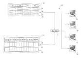
- FIG. 1 is a network architecture diagram showing aspects of a storage system 100 that includes several virtualized clusters 5 A- 5 B.
- a virtualized storage cluster (also referred to herein as a “storage cluster” or a “cluster”) is a cluster of different storage nodes that together expose a single storage device.
- the clusters 5 A- 5 B include the storage server computers 2 A- 2 G (also referred to herein as “storage nodes” or a “node”) that are operative to read and write data to one or more mass storage devices, such as hard disk drives.
- the cluster 5 A includes the nodes 2 A- 2 D and the cluster 5 B includes the nodes 2 E- 2 G.
- the nodes within a cluster may be housed in a one-rack space unit storing up to four hard disk drives.
- the node 2 A is a one-rack space computing system that includes four hard disk drives 4 A- 4 D.
- each node may be housed in a three-rack space unit storing up to fifteen hard disk drives.
- the node 2 E includes fifteen hard disk drives 4 A- 4 N.
- Other types of enclosures may also be utilized that occupy more or fewer rack units and that store fewer or more hard disk drives.
- the type of storage enclosure and number of hard disk drives utilized is not generally significant to the implementation of the embodiments described herein. Any type of storage enclosure and virtually any number of hard disk devices or other types of mass storage devices may be utilized.
- multiple storage nodes are configured together to create a virtualized storage cluster.
- the nodes 2 A- 2 D have been configured as a storage cluster 5 A and the nodes 2 E- 2 G have been configured as a storage cluster 5 B.
- each of the storage nodes 2 A- 2 G is utilized to field I/O operations independently, but are together exposed to the initiator of the I/O operation as a single device.
- a storage cluster may include any number of storage nodes.
- a virtualized cluster in which each node contains an independent processing unit, and in which each node can field I/Os independently (and route them according to the cluster layout) is called a horizontally virtualized, or peer, cluster.
- a cluster in which each node provides storage but the processing and mapping is done completely or primarily in a single node, is called a vertically virtualized cluster.
- data may be striped across the nodes of each storage cluster.
- the cluster 5 A may stripe data across the storage nodes 2 A, 2 B, 2 C, and 2 D.
- the cluster 5 B may similarly stripe data across the storage nodes 2 E, 2 F, and 2 G.
- Striping data across nodes generally ensures that different I/O operations are fielded by different nodes, thereby utilizing all of the nodes simultaneously, and that the same I/O operation is not split between multiple nodes. Striping the data in this manner provides a boost to random I/O performance without decreasing sequential I/O performance.
- Data striped across the nodes of a storage cluster may be organized into “zones.” A “zone” represents the amount of data that is stored on each storage node in a storage cluster when data is striped across the storage nodes.
- each storage server computer 2 A- 2 G includes one or more network ports operatively connected to a network switch 6 using appropriate network cabling. It should be appreciated that, according to embodiments of the invention, Ethernet or Gigabit Ethernet may be utilized. However, it should also be appreciated that other types of suitable physical connections may be utilized to form a network of which each storage server computer 2 A- 2 G is a part. Through the use of the network ports and other appropriate network cabling and equipment, each node within a cluster is communicatively connected to the other nodes within the cluster. Many different types and number of connections may be made between the nodes of each cluster.
- Each cluster 5 A- 5 B is also connected to a network switch 6 .
- the network switch 6 is connected to one or more client computers 8 A- 8 N (also referred to herein as “initiators”). It should be appreciated that other types of networking topologies may be utilized to interconnect the clients and the clusters 5 A- 5 B. It should also be appreciated that the initiators 8 A- 8 N may be connected to the same local area network (“LAN”) as the clusters 5 A- 5 B or may be connected to the clusters 5 A- 5 B via a distributed wide area network, such as the Internet. An appropriate protocol, such as the Internet Small Computer Systems Interface (“iSCSI”) protocol may be utilized to enable the initiators 8 A- 8 D to communicate with and utilize the various functions of the storage clusters 5 A- 5 B over a wide area network such as the Internet.
- LAN local area network
- iSCSI Internet Small Computer Systems Interface
- the storage node 2 A stores the zones 204 A, 204 E, 204 I, 204 M, 204 Q, 204 U, and 204 Y.
- the storage node 2 B stores the zones 204 B, 204 F, 204 J, 204 N, 204 R, 204 S, 204 W, and 204 A.
- the storage node 2 C stores the zones 204 C, 204 G, 204 K, 204 O, 204 S, 204 W, and 204 AA.
- the storage node 2 D stores the zones 204 D, 204 H, 204 L, 204 P, 204 T, 204 X, and 204 BB.
- the storage capacity exposed by the storage cluster 5 A shown in FIG. 2 has also been divided into two tiers 202 A- 202 B.
- a tier represents a portion of the storage capacity of a storage cluster.
- the tier 202 A is implemented utilizing expensive high performance mass storage devices, such as serial attached SCSI (“SAS”) hard disk drives.
- the tier 202 B is implemented utilizing less expensive but lower performance mass storage devices, such as serial advanced technology attachment (“SATA”) hard disk drives.
- SAS serial attached SCSI
- SATA serial advanced technology attachment
- the zones 204 A- 204 P are stored in the tier 202 A while the zones 204 Q- 204 BB are stored in the tier 202 B.
- the zones 204 A- 204 P stored in the tier 202 A have been organized using a chained declustered configuration.
- a chained declustered configuration ensures that all data is stored on at least two nodes of a storage cluster. For instance, as shown in FIG. 2 , the same data is stored in zones 204 A and 204 B. The same data is also stored in zones 204 C and 204 D, etc. In this manner, data is stored within at least two nodes of a storage cluster without the need for calculating parity as in a RAID configuration. This type of configuration, however, utilizes only 50% of the available storage.
- the zones 204 Q- 204 BB stored in the tier 202 B have been organized using a networked RAID configuration, in this case a networked RAID-5 configuration.
- a parity zone must be computed for each stripe and stored in a node of the storage cluster.
- the zone 204 T represents the parity zone for the zones 204 Q- 204 S.
- the zone 204 W represents the parity zone for the zones 204 U- 204 V and 204 X.
- the zone 204 Z represents the parity zone for the zones 204 Y and 204 AA- 204 BB.
- the storage cluster 5 A is operative to maintain information regarding the age, frequency of access, and other characteristics of the data stored on the storage nodes 2 A- 2 D.
- Frequently used data contained in zones stored in the tier 202 B is moved in the background to the tier 202 A. This process is referred to herein as “promotion.”
- Infrequently used data that is stored in zones in the tier 202 A is moved in the background to the tier 202 B. This process is referred to herein as “demotion.”
- the size of zones in the tier 202 A is the same as the size of zones in the tier 202 B. This process is described in further detail below with respect to FIG. 3 .
- FIG. 3 is a flow diagram showing a routine 300 that shows aspects of an illustrative process performed by the storage cluster 5 A for tiering its storage capacity and for migrating data between the two tiers 202 A- 202 B in one implementation.
- routine 300 shows aspects of an illustrative process performed by the storage cluster 5 A for tiering its storage capacity and for migrating data between the two tiers 202 A- 202 B in one implementation.
- the logical operations described herein are implemented (1) as a sequence of computer implemented acts or program modules running on a computing system and/or (2) as interconnected machine logic circuits or circuit modules within the computing system. The implementation is a matter of choice dependent on the performance and other requirements of the computing system.
- the routine 300 begins at operation 302 , where a portion of the storage capacity of the storage cluster 5 A is allocated to the tier 202 A. The routine 300 then continues to operation 304 , where another portion of the storage capacity of the storage cluster 5 A is allocated to the tier 202 B. Once the tiers 202 A and 202 B have been allocated, the cluster 5 A begins fielding I/Os and storing data at operation 306 .
- the cluster 5 A maintains statistics regarding the age, frequency of use, and other statistics regarding the stored data.
- the storage cluster 5 A utilizes these statistics at operation 308 to demote infrequently used data stored on the tier 202 A to the tier 202 B.
- the demotion process involves only moving a zone from the tier 202 A to the tier 202 B.
- the storage cluster 5 A utilizes the maintained statistics to promote frequently used data stored on the tier 202 B to the tier 202 A.
- the promotion process involves only moving a zone from the tier 202 B to the tier 202 A. More efficient mechanisms of promoting and demoting zones will be presented below with reference to FIGS. 4-7 .
- the routine 300 returns to operation 306 , where the cluster 5 A continues to field I/Os and promote and demote zones in the manner described above.
- FIGS. 4-5 illustrates the process of demoting a zone 204 A from a chained declustered tier 202 A to the network raid tier 202 B.
- the storage cluster 5 A has four nodes 2 A- 2 D.
- the zone 204 A is split into three sub-zones 404 A- 404 C.
- the parity 406 of the three sub-zones 404 A- 404 C is computed, for instance, by performing an XOR operation on the data stored in the three sub-zones 404 A- 404 C.
- the sub-zones 404 A- 404 C and the parity 406 are then stored in the tier 202 B on different storage nodes. For instance, the sub-zone 404 A is stored on the node 2 A, the sub-zone 404 B is stored on the node 2 B, the sub-zone 404 C is stored on the node 2 C, and the parity 406 is stored on the node 2 D. This process is illustrated further with respect to FIG. 5 .
- FIG. 5 is a flow diagram showing an illustrative routine 500 for demoting data from a first tier in a storage cluster to a second tier of the storage cluster in one implementation that utilizes sub-zones.
- the routine 500 begins at operation 502 , where the zone to be demoted is locked locally at the storage node where it is stored. This prevents any initiator I/Os from accessing the zone to be demoted while the operation is performed. Once the zone to be demoted has been locally locked, the routine 500 continues to operation 504 , where the zone to be demoted is read. Once the zone to be demoted has been read, the routine 500 continues to operation 506 .
- the zone to be demoted is divided into sub-zones.
- the number of sub-zones is dependent on the number of storage nodes in the cluster. Typically, if there are N storage nodes in the cluster, the zone will be divided into N ⁇ 1 sub-zones.
- the routine 500 continues to operation 508 , where the parity of the sub-zones is computed. In one implementation, this is accomplished by performing an XOR operation on the sub-zones. Once the parity has been computed, the routine 500 continues to operation 510 , where the sub-zones and the parity are written to the RAID tier of different nodes within the cluster in the manner described above with respect to FIG. 4 .
- the local lock on the zone to be demoted is released at operation 512 . It should be appreciated that through the use of this algorithm the need for networked reads, networked locks, and large bottle-necking parity computations are avoided.
- the routine 500 then continues to operation 514 , where it ends.
- a zone may be promoted from the networked RAID tier to the chained declustered-configured tier using sub-zones in the reverse manner. For instance, according to one implementation, a zone is promoted by first reading a sub-zone from each of the storage nodes in the second tier. The sub-zones are then assembling into a zone. The assembled zone is then stored in the chained declustered-configured tier of the storage cluster.
- each node in a cluster may restripe its own zones independently with minimal cross-node locking of I/Os.
- the process of restriping will be approximately ten times faster than if the restriping is done in the traditional manner. This kind of performance improvement makes it feasible to use the configuration in a tiered environment also.
- FIGS. 6 and 7 illustrate the further optimization.
- FIG. 6 illustrates a process for demoting a zone 204 A by subdividing each of the sub-zones 404 A- 404 C even further.
- the sub-zones 404 A- 404 C are divided into smaller stripes rather than storing the sub-zones contiguously on each node in the manner described above. For example, if a zone is 3 MB in size, it is divided into three 1 MB sub-zones.
- the demotion of the zone 204 A shown in FIG. 6 illustrates this process even further.
- the sub-zone 404 A has been subdivided into the stripes 606 A- 606 D.
- the sub-zone 404 B has been subdivided into the stripes 606 E- 606 H.
- the sub-zone 404 C has been divided into the stripes 606 I- 606 L.
- the parity 406 includes stripes 606 M- 606 Q that include the parity for each of the stripes.
- the stripes 606 M, 606 A, 606 E, and 6061 are stored on the node 2 A
- the stripes 606 B, 606 N, 606 F, and 606 J are stored on the node 2 B
- the stripes 606 C, 606 G, 606 P, and 606 K are stored on the node 2 C
- the stripes 606 D, 606 H, 606 L, and 606 Q are stored on the node 2 D.
- FIG. 7 illustrates this process further.
- FIG. 7 is a flow diagram showing an illustrative routine 700 for demoting data from a first tier in a storage cluster to a second tier of the storage cluster in one implementation that further divides sub-zones into stripes.
- the routine 700 begins at operation 702 , where the zone to be demoted is locked locally at the storage node where it is stored. This prevents any initiator I/Os from accessing the zone to be demoted while the zone operation is performed. Once the zone to be demoted has been locally locked, the routine 700 continues to operation 704 , where the zone to be demoted is read. Once the zone to be demoted has been read, the routine 700 continues to operation 706 .
- the zone to be demoted is divided into sub-zones.
- the routine 700 continues to operation 708 , where each sub-zone is divided into stripes and the parity of the stripes is computed. In one implementation, this is accomplished by performing an XOR operation on the stripes.
- the routine 700 continues to operation 710 , where the stripes and the parity are written to the RAID tier of different nodes within the cluster in the manner described above with respect to FIG. 6 .
- the local lock on the zone to be demoted is released at operation 712 .
- a zone may be promoted in the reverse manner by reading stripes from each node in the storage cluster, assembling the stripes into sub-zones, assembling the sub-zones into a zone, and storing the assembled zone in the chained declustered-configured tier of the storage cluster. From operation 712 , the routine 700 continues to operation 714 , where it ends.
- the first is optimization for performance.
- EXCHANGE SERVER mail system from MICROSOFT CORPORATION
- databases typically deliver 8 kB random I/Os. It is, therefore, possible to align the stripe size with the size of the typical I/O. This allows a performance boost for both sequential and random I/Os of that size, since each I/O is completed in a particular node but both sequential and random I/Os fall in different boxes.
- zone sizes in which the parent and child zone sizes are multiples of each other with the quotient being a multiple of the number of nodes minus one.
- the parent zone size is 1 MB and a four node RAID-5 is to be implemented, it becomes impossible to divide 1 MB into three zones of equal size. If, as a compromise, the space is divided into four quarter-MB sub-zones, storing them on the three nodes will result in an imbalance. While it is possible to track these imbalances, this adds complexity to the algorithm, and it may be preferable to let the imbalance be with space on the other two nodes being allocated but not used. However, this results in two quarter-MB sub-zones being wasted on the two other nodes. If, instead, smaller sub-zones are used, the amount of wastage is much smaller as a result.
- zone size may be closer to the native page size.
- the zone size permits the I/O structures used for reading data from the local machine to be split into multiple structures without performing a memory copy, and fired to different remote machines.
- each stripe must be read in its entirety according to an old layout, called a “map,” and then be rewritten on all of the nodes according to a new map that corresponds to the new number of nodes, while making sure the appropriate locks have been acquired.
- This can be a cumbersome process, especially in the case of RAID-5; it may even be preferable not to expand the number of nodes at all for new I/Os and instead use the new mapping only for new I/Os. However, this compromises on the performance of the cluster.
- the data placement algorithm (“DPA”) described in co-pending U.S. patent application Ser. No. 11/551,274, filed on Oct. 20, 2006, and entitled “Expanding the Storage Capacity of a Virtualized Data Storage System”, and in co-pending U.S. patent application Ser. No. 11/551,291, filed on Oct. 20, 2006, and entitled “Providing Redundancy in a Storage System” provides a solution to this issue.
- the DPA includes a series of maps that fix a layout of zones for a certain number of nodes.
- the DPA has two unique properties.
- the DPA ensures that when a new storage node is added to a cluster and data is re-striped between the storage nodes, only data that will subsequently reside in the new storage node is moved to the new storage node during re-striping.
- the DPA also ensures that no movement of data occurs between two storage nodes that existed in the storage cluster prior to the addition of the new storage node. So, a chained declustered setup can be expanded effortlessly and efficiently using an implementation of the DPA. Other mechanisms may also be utilized to stripe data across the storage nodes of a storage cluster.
- the DPA can also be used for expanding network RAID-5 implementations. This is accomplished by numbering all sub-zones, including the data and parity, in sequential order, and then following the DPA tables to expand. This expansion is not exactly the same as the expansion of a corresponding RAID-5 on disks, since the number of parity zones remains the same for the old and new configuration (instead of decreasing to reflect the larger number of zones that share a parity zone). However, the benefits due to improved restriping time outweigh the loss in space. The performance in this case scales the same way as with conventional RAID-5 implementations.
- U.S. patent application Ser. No. 11/551,274 and U.S. patent application Ser. No. 11/551,291 identified above describe the DPA in detail and are expressly incorporated herein by reference in their entirety.
- network RAID By utilizing the algorithms described in this document, it is possible to circumvent two of the most restrictive drawbacks of network RAID: performance and migration delay.
- performance of network RAID is typically low, but using it in an effective tiered storage server as presented herein allows the user to utilize faster chained declustered storage for front-line I/Os, and reserves the network RAID for data that is infrequently accessed.
- Migration delay is mitigated by using an adaptive zone size, through the concept of sub-zoning. In this way, an effective tiered storage cluster, using different levels of RAID, provide greatly improved TCO of a storage system, while maintaining high levels of data protection and average performance.
- FIG. 8 shows an illustrative computer architecture for a computer 800 capable of executing the software components described herein for implementing network RAID in a virtual storage cluster.
- the computer architecture shown in FIG. 8 provides a simplified view of the architecture of a conventional server computer 802 and may be utilized to implement the storage nodes 2 .
- FIG. 8 and the following discussion are intended to provide a brief, general description of a suitable computing environment in which the embodiments described herein may be implemented. While the technical details are presented herein in the general context of program modules that execute in conjunction with the execution of an operating system, those skilled in the art will recognize that the embodiments may also be implemented in combination with other program modules.
- program modules include routines, programs, components, data structures, and other types of structures that perform particular tasks or implement particular abstract data types.
- program modules may be located in both local and remote memory storage devices.
- the server computer 802 includes a baseboard, or “motherboard”, which is a printed circuit board to which a multitude of components or devices may be connected by way of a system bus or other electrical communication path.
- a CPU 822 operates in conjunction with a chipset 852 .
- the CPU 822 is a standard central processor that performs arithmetic and logical operations necessary for the operation of the computer.
- the server computer 802 may include a multitude of CPUs 822 .
- the chipset 852 includes a north bridge 824 and a south bridge 826 .
- the north bridge 824 provides an interface between the CPU 822 and the remainder of the computer 802 .
- the north bridge 824 also provides an interface to a random access memory (“RAM”) used as the main memory 854 in the computer 802 and, possibly, to an on-board graphics adapter 830 .
- the north bridge 824 may also include functionality for providing networking functionality through a gigabit Ethernet adapter 828 .
- the gigabit Ethernet adapter 828 is capable of connecting the computer 802 to another computer via a network. Connections which may be made by the network adapter 828 may include LAN or WAN connections. LAN and WAN networking environments are commonplace in offices, enterprise-wide computer networks, intranets, and the internet.
- the north bridge 824 is connected to the south bridge 826 .
- the south bridge 826 is responsible for controlling many of the input/output functions of the computer 802 .
- the south bridge 826 may provide one or more universal serial bus (“USB”) ports 832 , a sound adapter 846 , an Ethernet controller 860 , and one or more general purpose input/output (“GPIO”) pins 834 .
- the south bridge 826 may also provide a bus for interfacing peripheral card devices such as a graphics adapter 862 .
- the bus comprises a peripheral component interconnect (“PCI”) bus.
- PCI peripheral component interconnect
- the south bridge 826 may also provide a system management bus 864 for use in managing the various components of the computer 802 . Additional details regarding the operation of the system management bus 864 and its connected components are provided below.
- the south bridge 826 is also operative to provide one or more interfaces for connecting mass storage devices to the computer 802 .
- the south bridge 826 includes a serial advanced technology attachment (“SATA”) adapter for providing one or more serial ATA ports 836 and an ATA 100 adapter for providing one or more ATA 100 ports 844 .
- the serial ATA ports 836 and the ATA 100 ports 844 may be, in turn, connected to one or more mass storage devices storing an operating system 840 and application programs, such as the SATA disk drive 838 .
- an operating system 840 comprises a set of programs that control operations of a computer and allocation of resources.
- An application program is software that runs on top of the operating system software, or other runtime environment, and uses computer resources to perform application specific tasks desired by the user.
- the operating system 840 comprises the LINUX operating system. According to another embodiment of the invention the operating system 840 comprises the WINDOWS SERVER operating system from MICROSOFT CORPORATION. According to another embodiment, the operating system 840 comprises the UNIX or SOLARIS operating system. It should be appreciated that other operating systems may also be utilized.
- the mass storage devices connected to the south bridge 826 , and their associated computer-readable media, provide non-volatile storage for the computer 802 .
- computer-readable media can be any available media that can be accessed by the computer 802 .
- computer-readable media may comprise computer storage media and communication media.
- Computer storage media includes volatile and non-volatile, removable and non-removable media implemented in any method or technology for storage of information such as computer-readable instructions, data structures, program modules or other data.
- Computer storage media includes, but is not limited to, RAM, ROM, EPROM, EEPROM, flash memory or other solid state memory technology, CD-ROM, DVD, HD-DVD, BLU-RAY, or other optical storage, magnetic cassettes, magnetic tape, magnetic disk storage or other magnetic storage devices, or any other medium which can be used to store the desired information and which can be accessed by the computer.
- a low pin count (“LPC”) interface may also be provided by the south bridge 826 for connecting a “Super I/O” device 870 .
- the Super I/O device 870 is responsible for providing a number of input/output ports, including a keyboard port, a mouse port, a serial interface 872 , a parallel port, and other types of input/output ports.
- the LPC interface may also connect a computer storage media such as a ROM or a flash memory such as a NVRAM 848 for storing the firmware 850 that includes program code containing the basic routines that help to start up the computer 802 and to transfer information between elements within the computer 802 .
- the south bridge 826 may include a system management bus 864 .
- the system management bus 864 may include a BMC 866 .
- the BMC 866 is a microcontroller that monitors operation of the computer system 802 .
- the BMC 866 monitors health-related aspects associated with the computer system 802 , such as, but not limited to, the temperature of one or more components of the computer system 802 , speed of rotational components (e.g., spindle motor, CPU Fan, etc.) within the system, the voltage across or applied to one or more components within the system 802 , and the available or used capacity of memory devices within the system 802 .
- speed of rotational components e.g., spindle motor, CPU Fan, etc.
- the BMC 866 is communicatively connected to one or more components by way of the management bus 864 .
- these components include sensor devices for measuring various operating and performance-related parameters within the computer system 802 .
- the sensor devices may be either hardware or software based components configured or programmed to measure or detect one or more of the various operating and performance-related parameters.
- the BMC 866 functions as the master on the management bus 864 in most circumstances, but may also function as either a master or a slave in other circumstances.
- Each of the various components communicatively connected to the BMC 866 by way of the management bus 864 is addressed using a slave address.
- the management bus 864 is used by the BMC 866 to request and/or receive various operating and performance-related parameters from one or more components, which are also communicatively connected to the management bus 864 .
- the computer 802 may comprise other types of computing devices, including hand-held computers, embedded computer systems, personal digital assistants, and other types of computing devices known to those skilled in the art. It is also contemplated that the computer 802 may not include all of the components shown in FIG. 8 , may include other components that are not explicitly shown in FIG. 8 , or may utilize an architecture completely different than that shown in FIG. 8 .
Landscapes
- Engineering & Computer Science (AREA)
- Theoretical Computer Science (AREA)
- Physics & Mathematics (AREA)
- General Engineering & Computer Science (AREA)
- General Physics & Mathematics (AREA)
- Human Computer Interaction (AREA)
- Quality & Reliability (AREA)
- Information Retrieval, Db Structures And Fs Structures Therefor (AREA)
Abstract
Description
Claims (13)
Priority Applications (1)
| Application Number | Priority Date | Filing Date | Title |
|---|---|---|---|
| US13/681,692 US8856477B1 (en) | 2007-04-17 | 2012-11-20 | Networked raid in a virtualized cluster |
Applications Claiming Priority (4)
| Application Number | Priority Date | Filing Date | Title |
|---|---|---|---|
| US92386407P | 2007-04-17 | 2007-04-17 | |
| US12/104,123 US8001352B1 (en) | 2007-04-17 | 2008-04-16 | Networked raid in a virtualized cluster |
| US13/209,854 US8316202B1 (en) | 2007-04-17 | 2011-08-15 | Networked raid in a virtualized cluster |
| US13/681,692 US8856477B1 (en) | 2007-04-17 | 2012-11-20 | Networked raid in a virtualized cluster |
Related Parent Applications (1)
| Application Number | Title | Priority Date | Filing Date |
|---|---|---|---|
| US13/209,854 Continuation US8316202B1 (en) | 2007-04-17 | 2011-08-15 | Networked raid in a virtualized cluster |
Publications (1)
| Publication Number | Publication Date |
|---|---|
| US8856477B1 true US8856477B1 (en) | 2014-10-07 |
Family
ID=44358663
Family Applications (3)
| Application Number | Title | Priority Date | Filing Date |
|---|---|---|---|
| US12/104,123 Active 2030-02-01 US8001352B1 (en) | 2007-04-17 | 2008-04-16 | Networked raid in a virtualized cluster |
| US13/209,854 Active US8316202B1 (en) | 2007-04-17 | 2011-08-15 | Networked raid in a virtualized cluster |
| US13/681,692 Active US8856477B1 (en) | 2007-04-17 | 2012-11-20 | Networked raid in a virtualized cluster |
Family Applications Before (2)
| Application Number | Title | Priority Date | Filing Date |
|---|---|---|---|
| US12/104,123 Active 2030-02-01 US8001352B1 (en) | 2007-04-17 | 2008-04-16 | Networked raid in a virtualized cluster |
| US13/209,854 Active US8316202B1 (en) | 2007-04-17 | 2011-08-15 | Networked raid in a virtualized cluster |
Country Status (1)
| Country | Link |
|---|---|
| US (3) | US8001352B1 (en) |
Cited By (1)
| Publication number | Priority date | Publication date | Assignee | Title |
|---|---|---|---|---|
| US20140041553A1 (en) * | 2008-09-30 | 2014-02-13 | Calera Corporation | Co2-sequestering formed building materials |
Families Citing this family (22)
| Publication number | Priority date | Publication date | Assignee | Title |
|---|---|---|---|---|
| US8370597B1 (en) | 2007-04-13 | 2013-02-05 | American Megatrends, Inc. | Data migration between multiple tiers in a storage system using age and frequency statistics |
| CN101448023A (en) * | 2008-09-09 | 2009-06-03 | 创新科存储技术(深圳)有限公司 | Method for accessing logic unit in storage device and device |
| US8291178B2 (en) * | 2008-12-08 | 2012-10-16 | Apacer Technology Inc. | Machine-implemented method for categorizing storage media, and machine-implemented method for storing target codes |
| US8452932B2 (en) | 2010-01-06 | 2013-05-28 | Storsimple, Inc. | System and method for efficiently creating off-site data volume back-ups |
| US8453036B1 (en) * | 2010-02-01 | 2013-05-28 | Network Appliance, Inc. | System and method for dynamically resizing a parity declustered group |
| US9170892B2 (en) | 2010-04-19 | 2015-10-27 | Microsoft Technology Licensing, Llc | Server failure recovery |
| US9454441B2 (en) | 2010-04-19 | 2016-09-27 | Microsoft Technology Licensing, Llc | Data layout for recovery and durability |
| US9813529B2 (en) | 2011-04-28 | 2017-11-07 | Microsoft Technology Licensing, Llc | Effective circuits in packet-switched networks |
| US8402238B2 (en) * | 2010-05-18 | 2013-03-19 | Hitachi, Ltd. | Storage apparatus and control method thereof |
| US8504764B2 (en) * | 2010-08-30 | 2013-08-06 | Hitachi, Ltd. | Method and apparatus to manage object-based tiers |
| US8560801B1 (en) * | 2011-04-07 | 2013-10-15 | Symantec Corporation | Tiering aware data defragmentation |
| US9430367B1 (en) * | 2011-04-18 | 2016-08-30 | American Megatrends, Inc. | Systems and methods for active raid |
| US9778856B2 (en) * | 2012-08-30 | 2017-10-03 | Microsoft Technology Licensing, Llc | Block-level access to parallel storage |
| US11422907B2 (en) | 2013-08-19 | 2022-08-23 | Microsoft Technology Licensing, Llc | Disconnected operation for systems utilizing cloud storage |
| US9798631B2 (en) | 2014-02-04 | 2017-10-24 | Microsoft Technology Licensing, Llc | Block storage by decoupling ordering from durability |
| US10432723B2 (en) * | 2015-09-03 | 2019-10-01 | Toshiba Memory Corporation | Storage server and storage system |
| US10229014B1 (en) | 2015-11-19 | 2019-03-12 | American Megatrends, Inc. | Systems, methods and devices for performing fast RAID re-synchronization using a RAID sandwich architecture |
| US10423351B1 (en) * | 2017-04-28 | 2019-09-24 | EMC IP Holding Company LLC | System and method for capacity and network traffic efficient data protection on distributed storage system |
| CN109144791B (en) * | 2018-09-30 | 2020-12-22 | 北京金山云网络技术有限公司 | Data dump method, device and data management server |
| US11768620B2 (en) | 2020-04-24 | 2023-09-26 | Netapp, Inc. | Methods for handling storage devices with different zone sizes and devices thereof |
| US11822802B2 (en) | 2021-12-21 | 2023-11-21 | Hewlett Packard Enterprise Development Lp | Simplified raid implementation for byte-addressable memory |
| KR102750717B1 (en) * | 2023-11-23 | 2025-01-09 | 인하대학교 산학협력단 | Method for power-efficient video file placement on disk-array-based storage systems |
Citations (30)
| Publication number | Priority date | Publication date | Assignee | Title |
|---|---|---|---|---|
| US4942579A (en) | 1987-06-02 | 1990-07-17 | Cab-Tek, Inc. | High-speed, high-capacity, fault-tolerant error-correcting storage system |
| US5257367A (en) | 1987-06-02 | 1993-10-26 | Cab-Tek, Inc. | Data storage system with asynchronous host operating system communication link |
| US5502836A (en) | 1991-11-21 | 1996-03-26 | Ast Research, Inc. | Method for disk restriping during system operation |
| US5720027A (en) | 1996-05-21 | 1998-02-17 | Storage Computer Corporation | Redundant disc computer having targeted data broadcast |
| US5732238A (en) | 1996-06-12 | 1998-03-24 | Storage Computer Corporation | Non-volatile cache for providing data integrity in operation with a volatile demand paging cache in a data storage system |
| US5787459A (en) | 1993-03-11 | 1998-07-28 | Emc Corporation | Distributed disk array architecture |
| US5790774A (en) | 1996-05-21 | 1998-08-04 | Storage Computer Corporation | Data storage system with dedicated allocation of parity storage and parity reads and writes only on operations requiring parity information |
| US5893919A (en) | 1996-09-27 | 1999-04-13 | Storage Computer Corporation | Apparatus and method for storing data with selectable data protection using mirroring and selectable parity inhibition |
| US5974426A (en) | 1996-08-13 | 1999-10-26 | Samsung Electronics Co., Ltd. | Device and method for data recovery in a file system |
| US6098128A (en) | 1995-09-18 | 2000-08-01 | Cyberstorage Systems Corporation | Universal storage management system |
| US6275898B1 (en) * | 1999-05-13 | 2001-08-14 | Lsi Logic Corporation | Methods and structure for RAID level migration within a logical unit |
| US6327638B1 (en) | 1998-06-30 | 2001-12-04 | Lsi Logic Corporation | Disk striping method and storage subsystem using same |
| US20020161983A1 (en) | 2001-02-21 | 2002-10-31 | Storageapps Inc. | System, method, and computer program product for shared device of storage compacting |
| US6484235B1 (en) | 1999-05-03 | 2002-11-19 | 3Ware, Inc. | Methods and systems for dynamically distributing disk array data accesses |
| US20030163630A1 (en) | 2002-02-27 | 2003-08-28 | Aasheim Jered Donald | Dynamic data structures for tracking data stored in a flash memory device |
| US6718436B2 (en) | 2001-07-27 | 2004-04-06 | Electronics And Telecommunications Research Institute | Method for managing logical volume in order to support dynamic online resizing and software raid and to minimize metadata and computer readable medium storing the same |
| US20040255189A1 (en) | 2003-06-12 | 2004-12-16 | International Business Machines Corporation | Method and system for autonomously rebuilding a failed server and a computer system utilizing the same |
| US20050055402A1 (en) | 2003-09-09 | 2005-03-10 | Eiichi Sato | File sharing device and inter-file sharing device data migration method |
| US6901479B2 (en) | 2002-01-31 | 2005-05-31 | Kabushiki Kaisha Toshiba | Disk array apparatus for and method of expanding storage capacity dynamically |
| US20060031649A1 (en) * | 2000-05-24 | 2006-02-09 | Hitachi, Ltd. | Data storage system and method of hierarchical control thereof |
| US7020758B2 (en) | 2002-09-18 | 2006-03-28 | Ortera Inc. | Context sensitive storage management |
| US20060248273A1 (en) | 2005-04-29 | 2006-11-02 | Network Appliance, Inc. | Data allocation within a storage system architecture |
| US20070239747A1 (en) | 2006-03-29 | 2007-10-11 | International Business Machines Corporation | Methods, systems, and computer program products for providing read ahead and caching in an information lifecycle management system |
| US7324966B2 (en) | 2001-01-22 | 2008-01-29 | W.W. Grainger | Method for fulfilling an order in an integrated supply chain management system |
| US7360051B2 (en) * | 2004-09-10 | 2008-04-15 | Hitachi, Ltd. | Storage apparatus and method for relocating volumes thereof |
| US20080104343A1 (en) * | 2006-10-30 | 2008-05-01 | Hitachi, Ltd. | Storage control device and data migration method for storage control device |
| US7404102B2 (en) * | 2003-08-14 | 2008-07-22 | Compellent Technologies | Virtual disk drive system and method |
| US20080320247A1 (en) | 2005-05-12 | 2008-12-25 | Morfey Alistair G | Processor and interface |
| US7536529B1 (en) | 2005-06-10 | 2009-05-19 | American Megatrends, Inc. | Method, system, apparatus, and computer-readable medium for provisioning space in a data storage system |
| US7562200B1 (en) | 2005-06-10 | 2009-07-14 | American Megatrends, Inc. | Method, system, apparatus, and computer-readable medium for locking and synchronizing input/output operations in a data storage system |
-
2008
- 2008-04-16 US US12/104,123 patent/US8001352B1/en active Active
-
2011
- 2011-08-15 US US13/209,854 patent/US8316202B1/en active Active
-
2012
- 2012-11-20 US US13/681,692 patent/US8856477B1/en active Active
Patent Citations (30)
| Publication number | Priority date | Publication date | Assignee | Title |
|---|---|---|---|---|
| US5257367A (en) | 1987-06-02 | 1993-10-26 | Cab-Tek, Inc. | Data storage system with asynchronous host operating system communication link |
| US4942579A (en) | 1987-06-02 | 1990-07-17 | Cab-Tek, Inc. | High-speed, high-capacity, fault-tolerant error-correcting storage system |
| US5502836A (en) | 1991-11-21 | 1996-03-26 | Ast Research, Inc. | Method for disk restriping during system operation |
| US5787459A (en) | 1993-03-11 | 1998-07-28 | Emc Corporation | Distributed disk array architecture |
| US6098128A (en) | 1995-09-18 | 2000-08-01 | Cyberstorage Systems Corporation | Universal storage management system |
| US5720027A (en) | 1996-05-21 | 1998-02-17 | Storage Computer Corporation | Redundant disc computer having targeted data broadcast |
| US5790774A (en) | 1996-05-21 | 1998-08-04 | Storage Computer Corporation | Data storage system with dedicated allocation of parity storage and parity reads and writes only on operations requiring parity information |
| US5732238A (en) | 1996-06-12 | 1998-03-24 | Storage Computer Corporation | Non-volatile cache for providing data integrity in operation with a volatile demand paging cache in a data storage system |
| US5974426A (en) | 1996-08-13 | 1999-10-26 | Samsung Electronics Co., Ltd. | Device and method for data recovery in a file system |
| US5893919A (en) | 1996-09-27 | 1999-04-13 | Storage Computer Corporation | Apparatus and method for storing data with selectable data protection using mirroring and selectable parity inhibition |
| US6327638B1 (en) | 1998-06-30 | 2001-12-04 | Lsi Logic Corporation | Disk striping method and storage subsystem using same |
| US6484235B1 (en) | 1999-05-03 | 2002-11-19 | 3Ware, Inc. | Methods and systems for dynamically distributing disk array data accesses |
| US6275898B1 (en) * | 1999-05-13 | 2001-08-14 | Lsi Logic Corporation | Methods and structure for RAID level migration within a logical unit |
| US20060031649A1 (en) * | 2000-05-24 | 2006-02-09 | Hitachi, Ltd. | Data storage system and method of hierarchical control thereof |
| US7324966B2 (en) | 2001-01-22 | 2008-01-29 | W.W. Grainger | Method for fulfilling an order in an integrated supply chain management system |
| US20020161983A1 (en) | 2001-02-21 | 2002-10-31 | Storageapps Inc. | System, method, and computer program product for shared device of storage compacting |
| US6718436B2 (en) | 2001-07-27 | 2004-04-06 | Electronics And Telecommunications Research Institute | Method for managing logical volume in order to support dynamic online resizing and software raid and to minimize metadata and computer readable medium storing the same |
| US6901479B2 (en) | 2002-01-31 | 2005-05-31 | Kabushiki Kaisha Toshiba | Disk array apparatus for and method of expanding storage capacity dynamically |
| US20030163630A1 (en) | 2002-02-27 | 2003-08-28 | Aasheim Jered Donald | Dynamic data structures for tracking data stored in a flash memory device |
| US7020758B2 (en) | 2002-09-18 | 2006-03-28 | Ortera Inc. | Context sensitive storage management |
| US20040255189A1 (en) | 2003-06-12 | 2004-12-16 | International Business Machines Corporation | Method and system for autonomously rebuilding a failed server and a computer system utilizing the same |
| US7404102B2 (en) * | 2003-08-14 | 2008-07-22 | Compellent Technologies | Virtual disk drive system and method |
| US20050055402A1 (en) | 2003-09-09 | 2005-03-10 | Eiichi Sato | File sharing device and inter-file sharing device data migration method |
| US7360051B2 (en) * | 2004-09-10 | 2008-04-15 | Hitachi, Ltd. | Storage apparatus and method for relocating volumes thereof |
| US20060248273A1 (en) | 2005-04-29 | 2006-11-02 | Network Appliance, Inc. | Data allocation within a storage system architecture |
| US20080320247A1 (en) | 2005-05-12 | 2008-12-25 | Morfey Alistair G | Processor and interface |
| US7536529B1 (en) | 2005-06-10 | 2009-05-19 | American Megatrends, Inc. | Method, system, apparatus, and computer-readable medium for provisioning space in a data storage system |
| US7562200B1 (en) | 2005-06-10 | 2009-07-14 | American Megatrends, Inc. | Method, system, apparatus, and computer-readable medium for locking and synchronizing input/output operations in a data storage system |
| US20070239747A1 (en) | 2006-03-29 | 2007-10-11 | International Business Machines Corporation | Methods, systems, and computer program products for providing read ahead and caching in an information lifecycle management system |
| US20080104343A1 (en) * | 2006-10-30 | 2008-05-01 | Hitachi, Ltd. | Storage control device and data migration method for storage control device |
Non-Patent Citations (15)
| Title |
|---|
| U.S. Appl. No. 11/254,347, filed Oct. 20, 2005, entitled "Method, System, and Apparatus, and Computer-Readable Medium for Provisioning Space in a Data Storage System," Inventors: Chatterjee et al. |
| U.S. Appl. No. 11/417,801, filed May 4, 2006, entitled "Method, System, and Apparatus for Expanding Storage Capacity in a Data Storage System," Inventors: Chatterjee et al. |
| U.S. Appl. No. 12/101,236, filed Apr. 11, 2008, entitled "Data Migration Between Multiple Tiers in a Storage System Using Age and Frequency Statistics," Inventors: Chatterjee et al. |
| U.S. Appl. No. 12/101,238, filed Apr. 11, 2008, entitled "Data Migration Between Multiple Tiers in a Storage System Using Pivot Tables," Inventors: Chatterjee et al. |
| U.S. Appl. No. 12/104,135, filed Apr. 16, 2008, entitled "Container Space Management in a Data Storage System," Inventors: Chatterjee et al. |
| U.S. Appl. No. 12/425,123, filed Apr. 16, 2009, entitled "Provisioning Space in a Data Storage System," Inventors: Chatterjee et al. |
| U.S. Appl. No. 13/209,854, filed Aug. 15, 2011, entitled "Networked Raid in a Virtualized Cluster," Inventors: Chatterjee et al. |
| U.S. Notice of Allowance/Allowability dated Jan. 12, 2009 in U.S. Appl. No. 11/254,347. |
| U.S. Official Action dated Jul. 8, 2009 in U.S. Appl. No. 11/417,801. |
| U.S. Official Action dated Mar. 18, 2008 in U.S. Appl. No. 11/254,347. |
| U.S. Official Action dated Mar. 30, 2009 in U.S. Appl. No. 11/417,801. |
| U.S. Official Action dated Nov. 5, 2010 in U.S. Appl. No. 12/101,238. |
| U.S. Official Action dated Oct. 28, 2010 in U.S. Appl. No. 12/104,135. |
| U.S. Official Action dated Oct. 8, 2008 in U.S. Appl. No. 11/254,347. |
| U.S. Official Action dated Sep. 4, 2007 in U.S. Appl. No. 11/254,347. |
Cited By (1)
| Publication number | Priority date | Publication date | Assignee | Title |
|---|---|---|---|---|
| US20140041553A1 (en) * | 2008-09-30 | 2014-02-13 | Calera Corporation | Co2-sequestering formed building materials |
Also Published As
| Publication number | Publication date |
|---|---|
| US8001352B1 (en) | 2011-08-16 |
| US8316202B1 (en) | 2012-11-20 |
Similar Documents
| Publication | Publication Date | Title |
|---|---|---|
| US8856477B1 (en) | Networked raid in a virtualized cluster | |
| US7991969B1 (en) | Method, system, apparatus, and computer-readable medium for improving disk array performance | |
| US7953929B1 (en) | Expanding the storage capacity of a virtualized data storage system | |
| US8639878B1 (en) | Providing redundancy in a storage system | |
| US10001947B1 (en) | Systems, methods and devices for performing efficient patrol read operations in a storage system | |
| US8010829B1 (en) | Distributed hot-spare storage in a storage cluster | |
| US9519438B1 (en) | Data migration between multiple tiers in a storage system using age and frequency statistics | |
| US8402209B1 (en) | Provisioning space in a data storage system | |
| US8260744B1 (en) | Method, system, apparatus, and computer-readable medium for taking and managing snapshots of a storage volume | |
| US8521685B1 (en) | Background movement of data between nodes in a storage cluster | |
| US10073621B1 (en) | Managing storage device mappings in storage systems | |
| US7778960B1 (en) | Background movement of data between nodes in a storage cluster | |
| US10140136B2 (en) | Distributed virtual array data storage system and method | |
| US8499136B1 (en) | Method, system, and apparatus for expanding storage capacity in a data storage system | |
| US8082407B1 (en) | Writable snapshots for boot consolidation | |
| US8732411B1 (en) | Data de-duplication for information storage systems | |
| US9547446B2 (en) | Fine-grained control of data placement | |
| EP3807767B1 (en) | Storage system spanning multiple failure domains | |
| CN107408074A (en) | Storage system framework | |
| US10769020B2 (en) | Sharing private space among data storage system data rebuild and data deduplication components to minimize private space overhead | |
| US9547616B2 (en) | High bandwidth symmetrical storage controller | |
| CN111587421B (en) | Method and system for power supply fault impedance of distributed storage system | |
| WO2016190893A1 (en) | Storage management | |
| US10229014B1 (en) | Systems, methods and devices for performing fast RAID re-synchronization using a RAID sandwich architecture | |
| US10713117B2 (en) | Storage system and method for controlling storage system |
Legal Events
| Date | Code | Title | Description |
|---|---|---|---|
| AS | Assignment |
Owner name: AMERICAN MEGATRENDS, INC., GEORGIA Free format text: ASSIGNMENT OF ASSIGNORS INTEREST;ASSIGNORS:CHATTERJEE, PARESH;GRANDHI, SURESH;MAHALINGAM, ANANDH;AND OTHERS;SIGNING DATES FROM 20080403 TO 20080408;REEL/FRAME:031151/0001 |
|
| STCF | Information on status: patent grant |
Free format text: PATENTED CASE |
|
| MAFP | Maintenance fee payment |
Free format text: PAYMENT OF MAINTENANCE FEE, 4TH YEAR, LARGE ENTITY (ORIGINAL EVENT CODE: M1551) Year of fee payment: 4 |
|
| AS | Assignment |
Owner name: AMERICAN MEGATRENDS INTERNATIONAL, LLC, GEORGIA Free format text: CHANGE OF NAME;ASSIGNOR:AMERICAN MEGATRENDS, INC.;REEL/FRAME:053007/0233 Effective date: 20190211 Owner name: AMZETTA TECHNOLOGIES, LLC,, GEORGIA Free format text: ASSIGNMENT OF ASSIGNORS INTEREST;ASSIGNOR:AMERICAN MEGATRENDS INTERNATIONAL, LLC,;REEL/FRAME:053007/0151 Effective date: 20190308 |
|
| FEPP | Fee payment procedure |
Free format text: ENTITY STATUS SET TO SMALL (ORIGINAL EVENT CODE: SMAL); ENTITY STATUS OF PATENT OWNER: SMALL ENTITY |
|
| MAFP | Maintenance fee payment |
Free format text: PAYMENT OF MAINTENANCE FEE, 8TH YR, SMALL ENTITY (ORIGINAL EVENT CODE: M2552); ENTITY STATUS OF PATENT OWNER: SMALL ENTITY Year of fee payment: 8 |
|
| FEPP | Fee payment procedure |
Free format text: 11.5 YR SURCHARGE- LATE PMT W/IN 6 MO, SMALL ENTITY (ORIGINAL EVENT CODE: M2556); ENTITY STATUS OF PATENT OWNER: SMALL ENTITY |
|
| MAFP | Maintenance fee payment |
Free format text: PAYMENT OF MAINTENANCE FEE, 12TH YR, SMALL ENTITY (ORIGINAL EVENT CODE: M2553); ENTITY STATUS OF PATENT OWNER: SMALL ENTITY Year of fee payment: 12 |