US8855382B2 - MRI mammography with facilitated comparison to other mammography images - Google Patents
MRI mammography with facilitated comparison to other mammography images Download PDFInfo
- Publication number
- US8855382B2 US8855382B2 US13/064,530 US201113064530A US8855382B2 US 8855382 B2 US8855382 B2 US 8855382B2 US 201113064530 A US201113064530 A US 201113064530A US 8855382 B2 US8855382 B2 US 8855382B2
- Authority
- US
- United States
- Prior art keywords
- dimensional
- image
- images
- comparison
- image processing
- Prior art date
- Legal status (The legal status is an assumption and is not a legal conclusion. Google has not performed a legal analysis and makes no representation as to the accuracy of the status listed.)
- Active, expires
Links
Images


Classifications
-
- G—PHYSICS
- G01—MEASURING; TESTING
- G01R—MEASURING ELECTRIC VARIABLES; MEASURING MAGNETIC VARIABLES
- G01R33/00—Arrangements or instruments for measuring magnetic variables
- G01R33/20—Arrangements or instruments for measuring magnetic variables involving magnetic resonance
- G01R33/44—Arrangements or instruments for measuring magnetic variables involving magnetic resonance using nuclear magnetic resonance [NMR]
- G01R33/48—NMR imaging systems
- G01R33/54—Signal processing systems, e.g. using pulse sequences ; Generation or control of pulse sequences; Operator console
- G01R33/56—Image enhancement or correction, e.g. subtraction or averaging techniques, e.g. improvement of signal-to-noise ratio and resolution
- G01R33/5608—Data processing and visualization specially adapted for MR, e.g. for feature analysis and pattern recognition on the basis of measured MR data, segmentation of measured MR data, edge contour detection on the basis of measured MR data, for enhancing measured MR data in terms of signal-to-noise ratio by means of noise filtering or apodization, for enhancing measured MR data in terms of resolution by means for deblurring, windowing, zero filling, or generation of gray-scaled images, colour-coded images or images displaying vectors instead of pixels
-
- A—HUMAN NECESSITIES
- A61—MEDICAL OR VETERINARY SCIENCE; HYGIENE
- A61B—DIAGNOSIS; SURGERY; IDENTIFICATION
- A61B5/00—Measuring for diagnostic purposes; Identification of persons
- A61B5/05—Detecting, measuring or recording for diagnosis by means of electric currents or magnetic fields; Measuring using microwaves or radio waves
- A61B5/055—Detecting, measuring or recording for diagnosis by means of electric currents or magnetic fields; Measuring using microwaves or radio waves involving electronic [EMR] or nuclear [NMR] magnetic resonance, e.g. magnetic resonance imaging
-
- A—HUMAN NECESSITIES
- A61—MEDICAL OR VETERINARY SCIENCE; HYGIENE
- A61B—DIAGNOSIS; SURGERY; IDENTIFICATION
- A61B5/00—Measuring for diagnostic purposes; Identification of persons
- A61B5/74—Details of notification to user or communication with user or patient; User input means
- A61B5/742—Details of notification to user or communication with user or patient; User input means using visual displays
- A61B5/7425—Displaying combinations of multiple images regardless of image source, e.g. displaying a reference anatomical image with a live image
Definitions
- Exemplary embodiments described herein relate generally to image processing method and apparatus—and more particularly to breast magnetic resonance imaging (MRI) processing techniques.
- MRI breast magnetic resonance imaging
- a magnetic resonance imaging (MRI) apparatus is an apparatus which acquires chemical and physical micro-information of a substance utilizing a phenomenon whereby a target nuclear spin population, when placed in a magnetic field, resonates with a high-frequency magnetic field rotating at a specific frequency (resonant frequency) in accordance with the intrinsic magnetic moment and existing magnetic field intensity of the magnetic field, and generates a signal (a nuclear magnetic resonance (NMR) signal) in a nuclear spin relaxation process.
- a target nuclear spin population when placed in a magnetic field, resonates with a high-frequency magnetic field rotating at a specific frequency (resonant frequency) in accordance with the intrinsic magnetic moment and existing magnetic field intensity of the magnetic field, and generates a signal (a nuclear magnetic resonance (NMR) signal) in a nuclear spin relaxation process.
- NMR nuclear magnetic resonance
- Such an MRI apparatus can acquire images of regions of the whole body, such as the head and neck, the abdomen and the spine. For this reason, it is often the case that the images acquired by the MRI apparatus are utilized for the purpose of diagnosis. Also, in recent years, MRI apparatus has been used to examine breasts too. It is reported that breast images acquired by MRI apparatus are particularly effective in early detection of breast cancer, diagnosing whether a lesion is benign or malignant, and diagnosing spread of a tumor.
- FIG. 1 is a simplified schematic block diagram of an exemplary embodiment of MRI apparatus
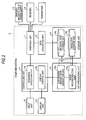
- FIG. 2 is a simplified schematic functional block diagram of the computer system of FIG. 1 ;
- FIG. 3 is a simplified schematic flowchart illustrating an exemplary embodiment of processing steps for generating a comparison breast image using the MRI apparatus of FIG. 1 ;
- FIG. 4 is a simplified schematic diagram illustrating an exemplary embodiment for generation of a cranio-caudal direction comparison breast image by the comparison breast image generation unit of FIG. 2 ;
- FIG. 5 is a simplified schematic diagram illustrating an exemplary embodiment for generation of a left-right direction comparison breast image by the comparison breast image generation unit of FIG. 2 ;
- FIG. 6 is a simplified schematic diagram illustrating an exemplary embodiment for generation of a cranio-caudal direction comparison image by the comparison breast image generation unit according to another embodiment.
- FIG. 7 is a simplified schematic diagram illustrating an exemplary embodiment for generation of a left-right direction comparison breast image by the comparison breast image generation unit according to another embodiment.
- a conventional MRI apparatus can be configured (e.g., by loading and executing appropriate computer program modules into suitable digital computer program memory) to effect the various functional blocks to be described below and/or special application hardware (e.g., an ASIC (application specific integrated circuit)) can be configured to effect the various functional blocks to be described below.
- special application hardware e.g., an ASIC (application specific integrated circuit)
- ASIC application specific integrated circuit
- FIG. 1 is a block diagram of MRI apparatus 100 which includes: a static magnetic-field magnet 1 , a set of orthogonal gradient magnetic-field coils 2 , controllable gradient magnetic-field power supplies 3 , patient couch 4 , patient couch controller 5 , RF transmission coil 6 , RF transmitter 7 , RF reception coil 8 , RF receiver 9 and computer system 10 .
- the static magnetic-field magnet 1 can, for example, comprise a hollow, cylindrical magnet structure that generates a substantially uniform static magnetic field in an imaging volume space within the static magnetic-field magnet 1 .
- the static magnetic-field magnet 1 can include, for example, one or more permanent magnets, a superconductive magnet, and the like.
- the set of gradient magnetic-field coils 2 can also comprise hollow, cylindrical coils disposed on an inner side of the static magnetic-field magnet 1 .
- the set of gradient magnetic-field coils 2 may be formed by an assembly of three coils corresponding to each of the usual orthogonal axes, X, Y and Z (i.e., which axes are each perpendicular to one another).
- the three coils individually receive an electric current supplied by the gradient magnetic-field power supplies 3 , described hereafter, and generate respective gradient magnetic fields of which magnetic field intensities respectively change along the X, Y and Z axes.
- the Z-axis direction chosen to be along same direction as the static magnetic-field magnetic field B 0 .
- the x-axis gradient magnetic field corresponds to the read-out (Gr) direction
- the y-axis gradient magnetic field corresponds to the phase-encoding (Ge) direction
- the z-axis gradient magnetic field corresponds to the slice select (Gs) direction.
- the slice-selection gradient magnetic-field Gs is used to select any arbitrarily desired imaging cross-sectional slice.
- the phase-encoding direction gradient magnetic-field Ge is mainly used to change the phase of an NMR response signal as a function of resonant nuclei spatial position (in the y-axis direction).
- the readout gradient direction magnetic-field Gr is used to change the frequency (i.e., to frequency encode) of an NMR response signal as a function of resonant nuclei spatial position (in the x-axis direction). As will be appreciated, this assignment of conventional orthogonal directions can be changed.
- the gradient magnetic-field power supplies 3 respectively supply the electric current to the individual gradient magnetic-field coils.
- the patient couch 4 includes a top plate 4 a on which a patient subject P is placed. Under control of the patient couch controlling unit 5 , the top plate 4 a is inserted into a cavity (opening to the imaging volume) within the static and gradient magnetic-field coils. Ordinarily, patient couch 4 is set such that a longitudinal direction of the patient couch 4 is parallel with a center axis of the static magnetic-field magnet 1 .
- the patient couch controlling unit 5 controls the patient couch 4 .
- the patient couch controlling unit 5 drives the patient couch 4 and can move the top plate 4 a in both the longitudinal and vertical directions.
- the RF transmission coil 6 is disposed radially inwardly of the gradient magnetic field coils.
- the RF transmission coil 6 receives high-frequency (RF) pulses from transmitter 7 and generates corresponding high-frequency (RF) magnetic fields B 1 .
- the RF transmitter 7 transmits the high-frequency RF pulse at a frequency corresponding to the Larmor frequency of a desired nuclei species via RF transmission coil 6 .
- the RF reception coil 8 receives a NMR RF response signal emanating from the subject P as induced to occur by the transmitted RF pulse.
- the RF reception coil 8 of present exemplary embodiments is for breast imaging, which is set on the top plate 4 a of the couch 4 . Procumbent subject P is placed upon the RF reception coil 8 while imaging. Upon receiving the NMR RF signal, the RF reception coil 8 outputs received NMR signals to RF receiver 9 .
- the RF receiver 9 generates detected NMR data for k-space based on the RF NMR signal outputted from RF reception coil 8 .
- the RF receiver 9 transmits the generated NMR signal to computer system.
- the computer system 10 performs overall control of the MRI apparatus 100 , collects data, reconstructs images, and the like.
- the computer system 10 can typically include interface unit 11 , data acquisition unit 12 , data processing unit 13 , storage unit 14 , display unit 15 , input unit 16 and controlling unit 17 .
- the interface unit 11 controls input and output of various signals exchanged between the computer system 10 and the controllable gradient magnetic-field power supplies 3 , the patient couch controller 5 , the RF transmitter 7 and RF receiver 9 .
- the data acquisition unit 12 acquires NMR signal transmitted from the RF receiver 9 via the interface unit 11 .
- the acquired NMR signal is stored in the storage unit 14 .
- the data processing unit 13 performs post-processing, namely, image reconstruction using processes such as multi-dimensional Fourier Transform, on the NMR signal data stored in storage unit 14 . As a result, the data processing unit 13 generates a display image.
- Storage unit 14 stores NMR signal data received by the data acquisition unit 12 , image data generated by the data processing unit 13 , and the like.
- Display unit 15 displays various pieces of information under control of controlling unit 17 .
- a display device such as a liquid crystal display (LCD) device can be used as display unit 15 .
- LCD liquid crystal display
- Input unit 16 receives various instructions and pieces of information input by an operator. Pointing devices such as a mouse and/or a track ball, and/or an input device such as a keyboard can be used accordingly as input unit 16 .
- Controlling unit 17 may include a central processing unit (CPU) (not shown), a memory, and the like to perform overall control of MRI apparatus 100 . Specifically, the controlling unit 17 may executes various acquisition sequences based on imaging conditions set by operator, thereby controlling the controllable gradient magnetic-field power supplies 3 , the RF transmitter 7 and RF receiver 9 .
- CPU central processing unit
- the computer system 10 executes an imaging sequence to acquire an MR signal from a three-dimensional space including the left and right breasts of the subject P. Also, the computer system 10 reconstructs three-dimensional image data of the left and right breasts based on the MR signal acquired by executing the imaging sequence.
- the computer system 10 generates two-dimensional images, one each of the left and right breasts, from the reconstructed three-dimensional image data and, by suitably rotating (and possibly combining chest wall portions of) the generated two-dimensional images, generates a two-dimensional image wherein the left and right breasts are disposed symmetrically (e.g., in a fashion similar or identical to traditional X-ray mammography depiction). Then, the computer system 10 causes the display unit 15 to display the generated two-dimensional image.
- CC cranio-caudal
- ML medio-lateral
- MLO medio-lateral oblique
- MRI apparatus can acquire three-dimensional breast image data.
- an axial image or a sagittal image, or an MIP (maximum intensity projection) image in the axial and sagittal directions is used for diagnostic reading. Consequently, when reading an MRI image in comparison with an X-ray mammography image, the line of sight and orientation of display for one of the images differs from those of the other mage being compared, meaning that it is difficult for a reader to comprehend a proper positional relationship between the two.
- left and right breast images imaged by the MRI apparatus 100 are displayed in a condition in which the left and right breasts are disposed symmetrically—possibly, if desired, even having the chest walls from these two images combined in the same way as traditionally done in X-ray mammography images. Consequently, in the case of comparing an MR image with an X-ray mammography image, the line of sight and orientation of display for each image are the same, meaning that it is possible for the reader to more easily comprehend positional relationships between the two. That is, according to the exemplary embodiment, it is possible to provide the reader with an MR image which can be easily more easily compared with an X-ray mammography image.
- a two-dimensional image generated by the computer system 10 that is, a two-dimensional image wherein the left and right breasts are disposed symmetrically (and in this example by also combining chest wall portions of the two-dimensional images of the left and right breasts), will be called a “comparison breast image” (CBI).
- CBI compare breast image
- FIG. 2 is a functional block diagram showing a more detailed configuration of the exemplary computer system 10 .
- a description will now be given centered on functions relating to the data processing unit 13 , storage unit 14 and controlling unit 17 shown in FIG. 1 .
- the storage unit 14 has an MR signal data storage unit 14 a and an image data storage unit 14 b .
- the MR signal data storage unit 14 a stores MR signal data acquired by the data acquisition unit 12 .
- the image data storage unit 14 b stores the image data generated by the data processing unit 13 .
- the controlling unit 17 has a sequence execution unit 17 a and a display control unit 17 b .
- the sequence execution unit 17 a executes various imaging sequences by generating various sequence execution data based on the imaging conditions set by the operator, and controlling the gradient magnetic-field power supply 3 , transmitter 7 and receiver 9 in accordance with the generated sequence execution data.
- the sequence execution data used herein are information defining a procedure for executing imaging, such as strength of the electric current supplied to the gradient magnetic-field coils 2 by the gradient magnetic-field power supply 3 and timing for supplying the electric current, strength of the RF signal transmitted to the RF transmission coils 6 by transmitter 7 and timing for transmitting the RF signal, and timing at which receiver 9 detects the NMR signal.
- the display control unit 17 b causes the display unit 15 to display the CBI generated by a comparison breast image generation unit 13 b to be described hereafter.
- the data processing unit 13 has an image reconstruction unit 13 a and the CBI generation unit 13 b .
- the image reconstruction unit 13 a reconstructs the three-dimensional image data of the left and right breasts of the subject P based on the MR signal data acquired by executing the imaging sequence for acquiring the magnetic resonance signal from the three-dimensional space including the left and right breasts of the subject.
- the comparison breast image generation unit 13 b generates a two-dimensional image wherein the two-dimensional images of the left and right breasts of the subject P are disposed symmetrically with the chest wall sides of the breasts combined (in this particular example) as the CBI from the three-dimensional image data reconstructed by the image reconstruction unit 13 a.
- FIG. 3 is a flowchart showing an exemplary processing procedure for generation of the CBI by MRI apparatus 100 .
- a detailed description will be given of exemplary processes carried out by each unit included in the controlling unit 17 and data processing unit 13 .
- computer system 10 when receiving a start instruction from the operator via input unit 16 (step S 301 , Yes), generates a three-dimensional image of the breasts of the subject P by appropriately controlling each unit of the MRI apparatus 100 (step S 302 ).
- sequence execution unit 17 a by controlling the gradient magnetic-field power supply 3 , transmitter 7 and receiver 9 , executes a desired imaging sequence for acquiring the magnetic resonance signal from a three-dimensional space including the left and right breasts of the subject.
- sequence execution unit 17 a may execute a gradient echo-cardiography imaging sequence wherein a one-dimensional frequency encode and a two-dimensional phase encode are combined.
- data acquisition unit 12 acquires MR signal data transmitted from receiver 9 by executing the heretofore described imaging sequence.
- image reconstruction unit 13 a conventionally reconstructs a three-dimensional image data of the left and right breasts of the subject P by performing three-dimensional Fourier Transformation on the MR signal data acquired by data acquisition unit 12 .
- data acquisition by the MRI apparatus is carried out from a region limited by being slice selected in one three-dimensional direction by a combination of an RF pulse whose bandwidth is limited and a slice-select gradient magnetic field.
- Imaging by acquiring data from a region limited by such slice-selection is called axial imaging, sagittal imaging, or coronal imaging according to the slice direction.
- Diagnosis using the MRI apparatus is carried out by saving and displaying each of axial, sagittal and coronal images, or images on which a maximum intensity projection (MIP) process is carried out along these axes.
- MIP maximum intensity projection
- axial or sagittal imaging is carried out in a breast examination. Therefore, hereafter, a description will be given of an exemplary case in which these two types of imagings are carried out.
- a mammary MRI examination it may happen that an MR imaging agent is injected through a vein, and that an extent to which a region of interest is imaged, a time until the region is imaged, a time until the imaging agent flows out, and the like, are used as criteria for judgment on whether a tumor is benign or malignant.
- an MR imaging agent is injected through a vein, and that an extent to which a region of interest is imaged, a time until the region is imaged, a time until the imaging agent flows out, and the like, are used as criteria for judgment on whether a tumor is benign or malignant.
- a time until the imaging agent is caused to flow outside the body it is only possible to inject the imaging agent once for one examination, meaning that it is desirable to acquire images of both left- and right-side breasts in one three-dimensional imaging sequence.
- a rectangular parallelepiped region in which both left- and right-side breasts are included can be set when positioning is determined for an imaging region.
- anterior-posterior direction of the subject is the up-down direction of the image
- the left-right direction of the subject is the left-right direction of the image
- the superior-inferior direction of the subject is the up-down direction of the image
- the anterior-posterior direction of the subject is the left-right direction of the image.
- a common MR image display method differs from a method whereby a result of cranio-caudal (CC) imaging or medio-lateral (ML) imaging, or medio-lateral oblique (MLO) imaging, which is normally carried out by X-ray mammography, is read disposed with weight put on the symmetry of the left and right breasts, meaning that when carrying out a reading of the MR image in comparison with diagnosis information based on X-ray mammography diagnosis information, it is difficult to comprehend a proper positional relationship between the two images, the line of sight and the orientation of display where one of these orientations differ in one image from those of the other image.
- CC cranio-caudal
- ML medio-lateral
- MLO medio-lateral oblique
- CBI generation unit 13 b determines whether or not to carry out a comparison display with an X-ray mammography image (step S 303 ). At this time, for example, CBI generation unit 13 b receives an operation of selecting one of a carrying out and non-carrying out of the comparison display, from the operator via input unit 16 . Then, the CBI generation unit 13 b , based on the received operator selection, determines whether or not to carry out a comparison display.
- step S 303 determines whether it is determined not to carry out a comparison display (step S 303 , No). If it is determined not to carry out a comparison display (step S 303 , No), CBI generation unit 13 b finishes the process without executing the procedure shown hereafter. Meanwhile, if it is determined to carry out a comparison display (step S 303 , Yes), CBI generation unit 13 b determines a display direction in which the CBI is displayed (step S 304 ).
- CBI generation unit 13 b determines either a direction corresponding to the cranio-caudal direction (CC direction) in the X-ray mammography imaging or a direction corresponding to the lateral direction (ML direction or MLO direction) as the display direction in which the CBI is to be displayed. At this time, for example, CBI generation unit 13 b receives an operation of selecting the direction in which the CBI is to be displayed, from the operator via input unit 16 . Then, CBI generation unit 13 b , based on the received operator selection, determines a CBI display direction.
- CC direction cranio-caudal direction
- ML direction or MLO direction the lateral direction
- CBI generation unit 13 b by performing an MIP process on three-dimensional image data generated by image reconstruction unit 13 a , generates a two-dimensional projection image in which the left and right breasts are projected in the cranio-caudal direction (step S 306 ). Also, CBI generation unit 13 b separates the generated two-dimensional projection image in the left-right direction as compared to a center and, by combining chest wall portions of the separated left and right two-dimensional projection images, generates a CBI wherein the left and right breasts are disposed symmetrically with the chest walls combined (step S 307 ).
- FIG. 4 is a diagram illustrating generation of a cranio-caudal direction comparison breast image by CBI generation unit 13 b.
- three-dimensional image data 405 are data generated by performing three-dimensional Fourier Transformation on MR signal data acquired by executing an imaging sequence using a three-dimensional imaging method.
- the three-dimensional image data 405 include a right breast 410 and a left breast 415 .
- A, P, R, L, H and F represent an anterior direction, a posterior direction, a right direction, a left direction, a head direction and a foot direction, respectively, in subject-domain coordinates.
- a dotted line 425 represents the vertical direction position of the upper end of the RF reception coil 8 or the upper end of the couch top plate 4 a .
- a dashed-dotted line 430 represents the left-right direction center of the apparatus-domain coordinate system.
- the dotted line 425 approximately coincides with the front side of the chest wall of the subject P.
- the dashed-dotted line 430 approximately coincides with the center in the left-right direction relative to the axis of the subject P.
- CBI generation unit 13 b When generating the cranio-caudal direction comparison breast image, for example, CBI generation unit 13 b carries out the MIP process in the head-foot (HF) direction shown by arrow 420 , and creates a two-dimensional projection image which forms the comparison breast image. At this time, CBI generation unit 13 b carries out the MIP process on a region 435 excluding a region on the back side (rear side) of a portion approximately corresponding to the chest wall.
- region 435 is a region including the chest wall, as heretofore described. Consequently, the right breast 410 and left breast 415 shall be understood to actually be connected in the vicinity of dotted line 425 .
- FIGS. 5-7 The same also applies in FIGS. 5-7 .
- a position a certain width away from the reference position toward the back side is set as a boundary between region 435 in which the MIP process is carried out and the excluded region. Because of this, it is possible to appropriately set a range in which the MIP process is carried out. Also, by setting a predetermined range using this method, it is possible to select only a region including one portion of the breasts and chest wall, and exclude regions such as the lungs and heart unnecessary in diagnosis.
- region 435 is selected by pattern recognition of the left and right breasts. More specifically, for example, a configuration may be such that changes in the lateral direction size of the left and right breasts from the front side to the rear side of the subject is recognized and, as the left and right breasts come closer and are connected in the vicinity of the chest wall, this connected position is recognized as the position of the chest wall, thus automatically selecting region 435 in which the MIP process is carried out.
- CBI generation unit 13 b carries out the MIP process in the limited region of three-dimensional image data 405 .
- a configuration may be such that CBI generation unit 13 b carries out the MIP process in the whole region of three-dimensional image data 405 and, subsequently, deletes an unnecessary region from a two-dimensional image obtained by the MIP process.
- CBI generation unit 13 b separates a two-dimensional projection image 440 obtained by the MIP process using a line 455 corresponding to the left-right direction center of apparatus-domain coordinates. Continuing, CBI generation unit 13 b rotates an image 460 , of the separated two images, including the right breast through 90 degrees in a clockwise direction, and rotates an image 465 including the left breast through 90 degrees in a counter-clockwise direction. Subsequently, CBI generation unit 13 b generates a comparison breast image 470 by combining the individual rotated images in such a way as to be symmetrical (e.g., with their chest walls combined if desired so as to more closely simulate an X-ray mammography image).
- the position of subject P is set in such a way that the center in the left-right direction relative to the axis of subject P coincides with the left-right direction center of the apparatus coordinates when the subject P is placed on couch 4 , when the image is separated into left and right in a position corresponding to the left-right direction center of the apparatus-domain coordinates, symmetry of the left and right breasts in the up-down direction, that is, in the left-right direction of the subject, of the combined image is maintained. Because of this, the resulting comparison breast image 470 is such that the line of sight and direction thereof coincide with the display method when carrying out a comparison reading with the two images, obtained in the CC direction imaging by X-ray mammography apparatus, disposed symmetrically. Consequently, it is easier to carry out a comparison of the X-ray mammography and MR images.
- comparison of the X-ray mammography image and MR image may be carried out by comparing images respectively displayed on each of different display units, but the exemplary embodiment is not limited to this.
- display control unit 17 b may adjust sizes of a mammography image obtained from outside the MRI system and the MRI comparison breast image 470 in such a way as to be of the same scale, and then display both images on the same display unit 15 .
- display control unit 17 b may compare sizes of the X-ray mammography image and MRI comparison breast image 470 with their respective full scales and, by scaling up or down at least one of the images, adjust the images in such a way that the breasts are displayed at the same size.
- a specific display form may be such that the X-ray mammography image and MRI comparison breast image 470 are disposed adjacent to each other and in parallel, or one of them may be displayed by switched alternate displays in accordance with an instruction input into input unit 16 .
- CBI generation unit 13 b by performing the MIP process on three-dimensional image data generated by image reconstruction unit 13 a in the left and right directions from the center of the three-dimensional image data, generates two-dimensional MIP images in which each of the left and right breasts is projected (step S 308 ). Also, CBI generation unit 13 b , by combining chest wall portions of the generated two-dimensional projection images (if desired), generates a comparison breast image wherein the left and right breasts are disposed symmetrically with the chest walls combined (step S 309 ).
- FIG. 5 Three-dimensional image data 405 shown in FIG. 5 are the same as those shown in FIG. 4 .
- CBI generation unit 13 b When generating the left-right direction comparison breast image, for example, CBI generation unit 13 b carries out the MIP process on a region 435 excluding a region on the back side (rear side) of a portion approximately corresponding to the chest wall, in the same way as in the case of generating a head-foot direction comparison breast image. That is, CBI generation unit 13 b carries out the MIP process on a region on the front side of a boundary line corresponding to the chest wall but, in this case, the region 435 is divided in two by a dashed-dotted line 430 representing the left-right direction center of the apparatus coordinates, and the individual regions are projected at the maximum value in the left and right directions shown by arrows 520 and 525 , respectively. Because of this, it is possible to obtain a left-right direction two-dimensional projection image 560 of the right breast and a left-right direction two-dimensional projection image 565 of the left breast.
- CBI generation unit 13 b After carrying out the MIP process, CBI generation unit 13 b generates the CBI 570 by rotating and combining the two-dimensional projection image 560 and two-dimensional projection image 565 obtained by the MIP process in such a way that the chest walls thereof are combined (if desired).
- the obtained CBI 570 is such that the line of sight and direction thereof approximately coincide with the display method when reading with the two X-ray mammography images acquired by the ML direction or MLO direction imaging disposed symmetrically.
- the display control unit 17 b causes display unit 15 to display the generated CBI (step S 310 ).
- sequence execution unit 17 a executes the imaging sequence for acquiring MR signal from a three-dimensional space including the left and right breasts of subject P.
- image reconstruction unit 13 a reconstructs a three-dimensional image data of the left and right breasts based on the MR signal acquired by sequence execution unit 17 a executing the selected imaging sequence.
- CBI generation unit 13 b generates the two-dimensional images, one each of the left and right breasts, from the three-dimensional image data reconstructed by image reconstruction unit 13 a and, by combining chest wall portions of the generated individual two-dimensional images, generates a CBI with the left and right breasts disposed symmetrically.
- display control unit 17 b causes display unit 15 to display the comparison breast image generated by CBI generation unit 13 b.
- the breast is imaged by the MRI apparatus 100 , in the same general geometric way as the X-ray mammography image and can be displayed with the left and right breasts being disposed symmetrically (with chest walls combined if desired to more closely parallel X-ray mammography images). Consequently, according to the exemplary embodiment, it is possible to provide the reader with an MR image that facilitates comparison with an X-ray mammography image. Also, according to the exemplary embodiment, as it is easy to compare the X-ray mammography image and MR image, it is also possible to carry out a diagnosis such as by determining a position of micro-calcification from mammography, and MR searching for invasive ductal breast cancer in approximately the same region.
- the comparison breast image is generated using the two-dimensional images.
- the comparison breast image is not limited to this technique.
- minimum intensity projection and/or value averaging (adding) projection processes can be used, as can any process for converting three-dimensional MR image data to two-dimensional images.
- the method of generating the comparison breast image does not necessarily include a process, such as the projection process, of converting three-dimensional MR image data to two-dimensional images.
- a configuration may be such that the CBI generation unit 13 b generates a plurality of axially cut cross-sectional MR images arranged in the left-right direction of subject P from three-dimensional MR image data reconstructed by image reconstruction unit 13 a , divides the thusly generated plurality of cross-sectional images into two image groups in opposite directions from the left-right direction center (and, if desired, combines the chest wall portion of each cross-sectional image included in the left-side image group and the chest wall portion of each corresponding cross-sectional image included in the right-side image), thereby generating a plurality of comparison breast images.
- FIG. 6 is a diagram illustrating generation of a cranio-caudal direction comparison image by CBI generation unit 13 b according to another exemplary embodiment.
- CBI generation unit 13 b selects regions of axially cut cross-sectional images from three-dimensional image data generated by image reconstruction unit 13 a , cuts out cross-sectional images, separates each cut-out cross-sectional image into left and right groups, and rotates and combines the left and right images.
- CBI generation unit 13 b obtains a two-dimensional image group 605 by cutting out a plurality of axially cut cross-sectional images from, for example, region 435 , among regions included in three-dimensional image data 405 shown in FIG. 6 , excluding a region on the back side of a portion approximately corresponding to the chest wall. Then, CBI generation unit 13 b , after halving the obtained image group 605 in the left-right direction center of the apparatus coordinates, rotates halved image groups 610 , and combines the left- and right-sides thereof, thereby generating a CBI group 615 . Because of this, it is possible to obtain a plurality of comparison breast images of which the line of sight and direction coincide with the display method when carrying out a reading with two images, acquired by the CC direction imaging by X-ray mammography, disposed symmetrically.
- a configuration may be such that CBI generation unit 13 b creates a plurality of sagittally cut cross-sectional images arranged in the cranio-caudal direction of subject P from the three-dimensional image data reconstructed by image reconstruction unit 13 a and, if desired, combines the chest wall portions of each pair of images, among the created plurality of cross-sectional images, positioned the same distance from the center of the three-dimensional image data, thereby generating a plurality of comparison breast images.
- FIG. 7 is a diagram illustrating generation of left-right comparison breast images by CBI generation unit 13 b according to another embodiment.
- CBI generation unit 13 b selects regions of sagittally cut cross-sectional images from three-dimensional image data generated by image reconstruction unit 13 a , cuts out the cross-sectional images, and rotates and combines the cut-out cross-sectional images for every two two-dimensional images with an equal distance from the left-right direction center of the apparatus coordinates.
- CBI generation unit 13 b obtains two-dimensional images by cutting out the plurality of sagittally cut cross-sectional images from, for example, region 435 , among regions included in three-dimensional image data 405 shown in FIG. 7 , excluding a region on the back side of a portion approximately corresponding to the chest wall. Then, CBI generation unit 13 b , by dividing the obtained images in a left-right direction center 430 of the apparatus coordinates, divides the two-dimensional images into image group 705 and image group 710 . In the example shown in FIG. 7 , image group 705 forms a set of two-dimensional images including the right-side breast, and image group 710 forms a set of two-dimensional images including the left-side breast.
- CBI generation unit 13 b generates comparison breast images by selecting images with an equal distance from the left-right direction center 430 of the apparatus coordinates, one from each of image group 705 and image group 710 , and combining each selected pair of images in such a way that the chest walls of the pair of images are combined (if desired) coinciding in the cranio-caudal direction of subject P. For example, as shown in FIG. 7 , CBI generation unit 13 b creates one comparison image using image data a and b positioned distance d away from the left-right direction center 430 of the apparatus coordinates.
- CBI generation unit 13 b generates a CBI group 715 by carrying out the same process for each pair of images positioned an equal distance from the left-right center 430 of the apparatus coordinates. Because of this, it is possible to obtain a plurality of comparison breast images in which the line of sight and direction approximately coincide with the display of images acquired by the ML direction or MLO direction X-ray mammography, disposed symmetrically.
- the MRI apparatus carries out continuous imaging in order to recognize a change of a signal value of tissues after injecting an imaging agent, generates a change curve of a signal value with respect to time (a time intensity curve) in each of pixels of time-series images obtained by the continuous imaging, generates images wherein values indicating a curve inclination, a time at which the signal value reaches a maximum value, and the like, in the change curve are correlated with the colors of the pixels, and provides the images as diagnostic images.
- Image data wherein some post-processing is performed on images, such as so-called color map images, reconstructed from the MR signal can also be displayed, by carrying out thereon the process described in the heretofore described exemplary embodiments, as a two-dimensional image wherein the left and right breasts are disposed symmetrically (including combining chest wall portions of the two-dimensional images of the left and right breasts, if desired).
- MRI apparatus it is possible to generate images of properties differing depending on various MRI sequences.
- images of tissues thusly weighted differ from one another.
- various blood vessel-weighted images obtained by imaging and non-imaging can be provided.
- image weighting a signal with a low diffusion coefficient which is called a diffusion-weighted image.
- the diffusion-weighted image as it can weight tissues with a high density, can be said to be suitable for detecting a malignant tumor, and is useful for a breast tumor diagnosis.
- a two-dimensional image is generated wherein a region in which the MIP or other projection is carried out in the way heretofore described onto each of the plurality of images of various properties is selected, and the left and right breasts are disposed symmetrically (and with the chest wall portions combined, if desired).
- display control unit 17 b may display each image in a display form in which it is also possible to compare an X-ray mammography image and a plurality of different kinds of MR images.
- the entire X-ray mammography image and a plurality of MR images may be displayed in parallel.
- any one of the X-ray mammography image and a plurality of MR images may be displayed at one time, and the display switched to different images by a predetermined input into input unit 16 .
- two images one of the plurality of MR images and the X-ray mammography image, may be displayed at one time, and the plurality of MR images displayed as switched by a predetermined input into input unit 16 .
- the MR image can be displayed as a two-dimensional image wherein the left and right breasts are disposed symmetrically by combining the chest wall portions of the two-dimensional images of the left and right breasts.
- the chest wall portion used herein does not necessarily indicate only a portion in which the chest wall is exposed, but may be a portion which is slightly inside the chest wall and actually does not include the chest wall. The point is that it is sufficient that a region comparable with the range of imaging by the X-ray mammography apparatus be displayed. Therefore, it is possible that the chest wall portions of left and right breasts may not be combined.
- the two-dimensional images may be disposed so that the chest walls are disposed substantially parallel to each other at a some (or no) distance from each other.
- MRI apparatus 100 In the heretofore described exemplary embodiments, a description has been given of a case in which MRI apparatus 100 is used, but the comparison image display process can also be similarly applied to, for example, an image processing apparatus connected to the MRI apparatus 100 via a network.
- an MRI apparatus 100 (or the like, possibly storing an archive of past-acquired MRI data) transfers three-dimensional MR signal data or three-dimensional image data, which are a source of data for generating the comparison breast image, to the image processing apparatus by way of the network or via a data recording medium.
- the image processing apparatus based on the three-dimensional MR signal data or three-dimensional image data transferred from the MRI apparatus, carries out the same process as the computer system 10 described in the heretofore described exemplary embodiments, and thereby generates and displays the comparison breast image.
- sequence execution unit 17 a display control unit 17 b , image reconstruction unit 13 a and CBI generation unit 13 b described in the exemplary embodiments can also be realized, at least in part, by suitable software modules. That is, the functions of the heretofore described units are realized by causing a computer to execute an image processing program regulating the exemplary processing procedure shown in FIG. 3 .
- the image processing program may be installed in advance in the computer, may be recorded in a removable recording medium, such as a magnetic disk, a magneto-optical disk, an optical disk, or a semiconductor memory, or may be distributed via a network, and installed in a computer apparatus as appropriate.
- MRI apparatus 100 is used, but the comparison image process can also be similarly applied to another medical diagnostic imaging apparatus such as, for example, an X-ray CT apparatus or a PET apparatus, other than an X-ray mammography apparatus.
- another medical diagnostic imaging apparatus such as, for example, an X-ray CT apparatus or a PET apparatus, other than an X-ray mammography apparatus.
Landscapes
- Health & Medical Sciences (AREA)
- Life Sciences & Earth Sciences (AREA)
- Physics & Mathematics (AREA)
- Engineering & Computer Science (AREA)
- Nuclear Medicine, Radiotherapy & Molecular Imaging (AREA)
- General Health & Medical Sciences (AREA)
- Radiology & Medical Imaging (AREA)
- Molecular Biology (AREA)
- Public Health (AREA)
- Biomedical Technology (AREA)
- Heart & Thoracic Surgery (AREA)
- Medical Informatics (AREA)
- Biophysics (AREA)
- Surgery (AREA)
- Animal Behavior & Ethology (AREA)
- High Energy & Nuclear Physics (AREA)
- Pathology (AREA)
- Veterinary Medicine (AREA)
- Artificial Intelligence (AREA)
- Computer Vision & Pattern Recognition (AREA)
- Signal Processing (AREA)
- Condensed Matter Physics & Semiconductors (AREA)
- General Physics & Mathematics (AREA)
- Magnetic Resonance Imaging Apparatus (AREA)
- Apparatus For Radiation Diagnosis (AREA)
Abstract
Description
Claims (22)
Applications Claiming Priority (5)
| Application Number | Priority Date | Filing Date | Title |
|---|---|---|---|
| JP2010077630 | 2010-03-30 | ||
| JP2010-11407 | 2010-03-30 | ||
| JP2010-77630 | 2010-03-30 | ||
| JP2011-69151 | 2011-03-28 | ||
| JP2011069151A JP6012931B2 (en) | 2010-03-30 | 2011-03-28 | Image processing apparatus and control program for image processing apparatus |
Publications (2)
| Publication Number | Publication Date |
|---|---|
| US20110243418A1 US20110243418A1 (en) | 2011-10-06 |
| US8855382B2 true US8855382B2 (en) | 2014-10-07 |
Family
ID=44958587
Family Applications (1)
| Application Number | Title | Priority Date | Filing Date |
|---|---|---|---|
| US13/064,530 Active 2032-05-03 US8855382B2 (en) | 2010-03-30 | 2011-03-30 | MRI mammography with facilitated comparison to other mammography images |
Country Status (2)
| Country | Link |
|---|---|
| US (1) | US8855382B2 (en) |
| CN (1) | CN102240210B (en) |
Cited By (1)
| Publication number | Priority date | Publication date | Assignee | Title |
|---|---|---|---|---|
| US20170055929A1 (en) * | 2015-08-27 | 2017-03-02 | Canon Kabushiki Kaisha | Image processing apparatus, image processing method, radiation imaging system, and non-transitory computer-readable storage medium |
Families Citing this family (8)
| Publication number | Priority date | Publication date | Assignee | Title |
|---|---|---|---|---|
| CN104011770B (en) | 2011-12-22 | 2017-03-22 | 皇家飞利浦有限公司 | Process and display breast images |
| EP2812880A1 (en) * | 2012-02-10 | 2014-12-17 | Koninklijke Philips N.V. | Clinically driven image fusion |
| CN103914697B (en) * | 2012-12-29 | 2018-08-31 | 上海联影医疗科技有限公司 | A kind of extracting method of breast 3-D view area-of-interest |
| CN104123729B (en) * | 2014-08-01 | 2017-04-26 | 湖北省肿瘤医院 | Two-viewing-angle mammography based calcification positioning method |
| KR20160139292A (en) * | 2015-05-27 | 2016-12-07 | 삼성전자주식회사 | Radio frequency surface coil and Magnetic resonance imaging system comprising the same |
| US20170042626A1 (en) * | 2015-07-31 | 2017-02-16 | Advanced Tactile Imaging, Inc. | Method and probe for providing tactile feedback in laparoscopic surgery |
| KR102003045B1 (en) * | 2015-12-08 | 2019-07-23 | 삼성전자주식회사 | Medical imaging apparatus and medical image processing method thereof |
| CN113520416A (en) * | 2020-04-21 | 2021-10-22 | 上海联影医疗科技股份有限公司 | A method and system for generating a two-dimensional image of an object |
Citations (9)
| Publication number | Priority date | Publication date | Assignee | Title |
|---|---|---|---|---|
| US6606400B1 (en) | 1998-08-20 | 2003-08-12 | Fuji Photo Film Co., Ltd. | Abnormal pattern detection processing method and system |
| US20080292164A1 (en) * | 2006-08-29 | 2008-11-27 | Siemens Corporate Research, Inc. | System and method for coregistration and analysis of non-concurrent diffuse optical and magnetic resonance breast images |
| US20090143668A1 (en) * | 2007-12-04 | 2009-06-04 | Harms Steven E | Enhancement of mri image contrast by combining pre- and post-contrast raw and phase spoiled image data |
| US20100022881A1 (en) * | 2006-09-22 | 2010-01-28 | Hiroshi Fujita | Ultrasound Breast Diagnostic System |
| US7828732B2 (en) * | 2000-11-24 | 2010-11-09 | U-Systems, Inc. | Breast cancer screening with adjunctive ultrasound mammography |
| US7885443B2 (en) * | 2005-11-14 | 2011-02-08 | Hologic, Inc. | Facilitating temporal comparison of medical images |
| US20110150313A1 (en) * | 2009-12-17 | 2011-06-23 | The Regents Of The University Of California | Method and Apparatus for Quantitative Analysis of Breast Density Morphology Based on MRI |
| US8126226B2 (en) * | 2007-09-20 | 2012-02-28 | General Electric Company | System and method to generate a selected visualization of a radiological image of an imaged subject |
| US8135452B2 (en) * | 2006-04-21 | 2012-03-13 | The Trustees Of The University Of Pennsylvania | Rapid 3-dimensional bilateral breast MR imaging |
Family Cites Families (3)
| Publication number | Priority date | Publication date | Assignee | Title |
|---|---|---|---|---|
| FR2818781B1 (en) * | 2000-12-22 | 2003-03-21 | Ge Med Sys Global Tech Co Llc | METHOD OF SIMULTANEOUSLY DISPLAYING ORGAN IMAGES |
| WO2006018816A2 (en) * | 2004-08-18 | 2006-02-23 | Koninklijke Philips Electronics N.V. | Display system for the evaluation of mammographies |
| JP2006061472A (en) * | 2004-08-27 | 2006-03-09 | Fuji Photo Film Co Ltd | Breast image display device, and program therefor |
-
2011
- 2011-03-30 CN CN201110077753.9A patent/CN102240210B/en active Active
- 2011-03-30 US US13/064,530 patent/US8855382B2/en active Active
Patent Citations (9)
| Publication number | Priority date | Publication date | Assignee | Title |
|---|---|---|---|---|
| US6606400B1 (en) | 1998-08-20 | 2003-08-12 | Fuji Photo Film Co., Ltd. | Abnormal pattern detection processing method and system |
| US7828732B2 (en) * | 2000-11-24 | 2010-11-09 | U-Systems, Inc. | Breast cancer screening with adjunctive ultrasound mammography |
| US7885443B2 (en) * | 2005-11-14 | 2011-02-08 | Hologic, Inc. | Facilitating temporal comparison of medical images |
| US8135452B2 (en) * | 2006-04-21 | 2012-03-13 | The Trustees Of The University Of Pennsylvania | Rapid 3-dimensional bilateral breast MR imaging |
| US20080292164A1 (en) * | 2006-08-29 | 2008-11-27 | Siemens Corporate Research, Inc. | System and method for coregistration and analysis of non-concurrent diffuse optical and magnetic resonance breast images |
| US20100022881A1 (en) * | 2006-09-22 | 2010-01-28 | Hiroshi Fujita | Ultrasound Breast Diagnostic System |
| US8126226B2 (en) * | 2007-09-20 | 2012-02-28 | General Electric Company | System and method to generate a selected visualization of a radiological image of an imaged subject |
| US20090143668A1 (en) * | 2007-12-04 | 2009-06-04 | Harms Steven E | Enhancement of mri image contrast by combining pre- and post-contrast raw and phase spoiled image data |
| US20110150313A1 (en) * | 2009-12-17 | 2011-06-23 | The Regents Of The University Of California | Method and Apparatus for Quantitative Analysis of Breast Density Morphology Based on MRI |
Non-Patent Citations (2)
| Title |
|---|
| C. Kuhl, "The Current Status of Breast MR Imaging, Part 1, Choice of Technique, Image Interpretation, Diagnostic Accuracy, and Transfer to Clinical Practice," Radiology, vol. 244, No. 2, pp. 356-378 (Aug. 2007). |
| E. Haacke, et al., "Physical Principles and Sequence Design," Magnetic Resonance Imaging, Chapter 23, pp. 697-700 (1999). |
Cited By (2)
| Publication number | Priority date | Publication date | Assignee | Title |
|---|---|---|---|---|
| US20170055929A1 (en) * | 2015-08-27 | 2017-03-02 | Canon Kabushiki Kaisha | Image processing apparatus, image processing method, radiation imaging system, and non-transitory computer-readable storage medium |
| US10092264B2 (en) * | 2015-08-27 | 2018-10-09 | Canon Kabushiki Kaisha | Image processing apparatus, image processing method, radiation imaging system, and non-transitory computer-readable storage medium |
Also Published As
| Publication number | Publication date |
|---|---|
| US20110243418A1 (en) | 2011-10-06 |
| CN102240210A (en) | 2011-11-16 |
| CN102240210B (en) | 2016-04-20 |
Similar Documents
| Publication | Publication Date | Title |
|---|---|---|
| US8855382B2 (en) | MRI mammography with facilitated comparison to other mammography images | |
| US7379573B2 (en) | Method and apparatus for processing images using three-dimensional ROI | |
| JP6012931B2 (en) | Image processing apparatus and control program for image processing apparatus | |
| RU2605517C2 (en) | Mri with correction of movement with the help of navigators, obtained by dixon method | |
| US6914429B2 (en) | MR imaging system and data acquisition method | |
| JP5575491B2 (en) | Medical diagnostic imaging equipment | |
| US10729355B2 (en) | Magnetic resonance imaging apparatus and imaging planning method | |
| CN104717920B (en) | Magnetic resonance imaging apparatus and magnetic resonance imaging method | |
| EP3358362A1 (en) | Mri with separation of fat and water signals | |
| KR20140096917A (en) | Magnetic resonance imaging system and magnetic resonance imaging method | |
| US20180374246A1 (en) | Image processing apparatus, magnetic resonance imaging apparatus, and storage medium | |
| US8488856B2 (en) | Magnetic resonance imaging apparatus and method of analyzing images provided thereby | |
| US11544842B2 (en) | Medical image diagnostic apparatus, medical imaging apparatus and medical imaging method | |
| EP3044605B1 (en) | Push-button vessel wall mri with 3d scout scan | |
| US20240090791A1 (en) | Anatomy Masking for MRI | |
| US11071469B2 (en) | Magnetic resonance method and apparatus for determining a characteristic of an organ | |
| US9833166B2 (en) | Magnetic resonance imaging apparatus configured to acquire target site diagnostic image data based on detection of target sites in prior acquired image data | |
| KR102092908B1 (en) | Magnetic Resonance Imaging Apparatus for Correcting Respiratory Movement | |
| US10466324B2 (en) | Method and magnetic resonance apparatus determining markings on a quantitative image data | |
| KR102257963B1 (en) | Apparatus for Detecting Respiratory Interval Using Histogram Cumulative Distribution of Respiratory Gating Signal | |
| CN108363027B (en) | Method for acquiring diagnostic measurement data of a heart and for examining a heart, and magnetic resonance system | |
| JP2023045877A (en) | Medical image processing device and medical image processing program | |
| Mengling et al. | Optimization of MR Acquisition for Brain Irradiation |
Legal Events
| Date | Code | Title | Description |
|---|---|---|---|
| AS | Assignment |
Owner name: KABUSHIKI KAISHA TOSHIBA, JAPAN Free format text: ASSIGNMENT OF ASSIGNORS INTEREST;ASSIGNOR:SUGIURA, SATOSHI;REEL/FRAME:026131/0875 Effective date: 20110330 Owner name: TOSHIBA MEDICAL SYSTEMS CORPORATION, JAPAN Free format text: ASSIGNMENT OF ASSIGNORS INTEREST;ASSIGNOR:SUGIURA, SATOSHI;REEL/FRAME:026131/0875 Effective date: 20110330 |
|
| STCF | Information on status: patent grant |
Free format text: PATENTED CASE |
|
| FEPP | Fee payment procedure |
Free format text: PAYOR NUMBER ASSIGNED (ORIGINAL EVENT CODE: ASPN); ENTITY STATUS OF PATENT OWNER: LARGE ENTITY |
|
| AS | Assignment |
Owner name: TOSHIBA MEDICAL SYSTEMS CORPORATION, JAPAN Free format text: ASSIGNMENT OF ASSIGNORS INTEREST;ASSIGNOR:KABUSHIKI KAISHA TOSHIBA;REEL/FRAME:038891/0693 Effective date: 20160316 |
|
| MAFP | Maintenance fee payment |
Free format text: PAYMENT OF MAINTENANCE FEE, 4TH YEAR, LARGE ENTITY (ORIGINAL EVENT CODE: M1551) Year of fee payment: 4 |
|
| MAFP | Maintenance fee payment |
Free format text: PAYMENT OF MAINTENANCE FEE, 8TH YEAR, LARGE ENTITY (ORIGINAL EVENT CODE: M1552); ENTITY STATUS OF PATENT OWNER: LARGE ENTITY Year of fee payment: 8 |