US8854052B2 - Sensor assembly and method of measuring the proximity of a machine component to a sensor - Google Patents
Sensor assembly and method of measuring the proximity of a machine component to a sensor Download PDFInfo
- Publication number
- US8854052B2 US8854052B2 US12/951,447 US95144710A US8854052B2 US 8854052 B2 US8854052 B2 US 8854052B2 US 95144710 A US95144710 A US 95144710A US 8854052 B2 US8854052 B2 US 8854052B2
- Authority
- US
- United States
- Prior art keywords
- signal
- emitter
- microwave
- frequencies
- power
- Prior art date
- Legal status (The legal status is an assumption and is not a legal conclusion. Google has not performed a legal analysis and makes no representation as to the accuracy of the status listed.)
- Active, expires
Links
Images


Classifications
-
- G—PHYSICS
- G01—MEASURING; TESTING
- G01B—MEASURING LENGTH, THICKNESS OR SIMILAR LINEAR DIMENSIONS; MEASURING ANGLES; MEASURING AREAS; MEASURING IRREGULARITIES OF SURFACES OR CONTOURS
- G01B7/00—Measuring arrangements characterised by the use of electric or magnetic techniques
- G01B7/02—Measuring arrangements characterised by the use of electric or magnetic techniques for measuring length, width or thickness
- G01B7/023—Measuring arrangements characterised by the use of electric or magnetic techniques for measuring length, width or thickness for measuring distance between sensor and object
-
- G—PHYSICS
- G01—MEASURING; TESTING
- G01B—MEASURING LENGTH, THICKNESS OR SIMILAR LINEAR DIMENSIONS; MEASURING ANGLES; MEASURING AREAS; MEASURING IRREGULARITIES OF SURFACES OR CONTOURS
- G01B15/00—Measuring arrangements characterised by the use of electromagnetic waves or particle radiation, e.g. by the use of microwaves, X-rays, gamma rays or electrons
Definitions
- the present application relates generally to power systems and, more particularly, to a sensor assembly and a method of measuring the proximity of a machine component relative to a sensor.
- Known machines may exhibit vibrations and/or other abnormal behavior during operation.
- One or more sensors may be used to measure and/or monitor such behavior and to determine, for example, an amount of vibration exhibited in a machine drive shaft, a rotational speed of the machine drive shaft, and/or any other operational characteristic of an operating machine or motor.
- Such sensors are coupled to a machine monitoring system that includes a plurality of monitors.
- the monitoring system receives signals from one or more sensors, performs at least one processing step on the signals, and transmits the modified signals to a diagnostic platform that displays the measurements to a user.
- At least some known machines use eddy current sensors to measure the vibrations in and/or a position of a machine component.
- the use of known eddy current sensors may be limited because a detection range of such sensors is only about half of a width of the eddy current sensing element.
- Other known machines use optical sensors to measure a vibration and/or a position of a machine component.
- known optical sensors may become fouled by contaminants and provide inaccurate measurements, and as such, may be unsuitable for industrial environments.
- known optical sensors may not be suitable for detecting a vibration and/or a position of a machine component through a liquid medium and/or a medium that includes particulates.
- a microwave sensor assembly in one embodiment, includes a signal processing device for generating at least one microwave signal that includes a pattern of frequencies and at least one probe coupled to the signal processing device.
- the probe includes an emitter configured to generate an electromagnetic field from the at least one microwave signal, wherein the emitter is detuned when an object is positioned within the electromagnetic field such that a loading signal is reflected from the emitter to the signal processing device.
- a power system in another embodiment, includes a machine including at least one component and a microwave sensor assembly positioned proximate to the at least one component.
- the microwave sensor assembly includes a signal processing device for generating at least one microwave signal that includes a pattern of frequencies and at least one probe coupled to the signal processing device.
- the probe includes an emitter configured to generate an electromagnetic field from the at least one microwave signal, wherein the emitter is detuned when an object is positioned within the electromagnetic field such that a loading signal is reflected from the emitter to the signal processing device.
- a method for measuring a proximity of a machine component to an emitter includes transmitting at least one microwave signal that includes a pattern of frequencies to an emitter and generating an electromagnetic field from the at least one microwave signal.
- a loading signal representative of a disruption of the electromagnetic field is generated, and the proximity of the machine component to the emitter is calculated based on the loading signal.
- FIG. 1 is a block diagram of an exemplary power system.
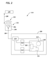
- FIG. 2 is a block diagram of an exemplary sensor assembly that may be used with the power system shown in FIG. 1 .
- FIG. 3 is a graphical view of an exemplary microwave signal that may be used with the sensor assembly shown in FIG. 2 .
- FIG. 4 is a graphical view of an exemplary power distribution of the microwave signal shown in FIG. 3 .
- FIG. 5 is a graphical view of an exemplary proximity response of the sensor assembly shown in FIG. 2 .
- FIG. 1 shows an exemplary power system 100 that includes a machine 102 .
- machine 102 may be, but is not limited to only being, a wind turbine, a hydroelectric turbine, a gas turbine, or a compressor.
- machine 102 may be any other machine used in a power system.
- machine 102 rotates a drive shaft 104 that is coupled to a load 106 , such as a generator.
- drive shaft 104 is at least partially supported by one or more bearings (not shown) housed within machine 102 and/or within load 106 .
- the bearings may be housed within a separate support structure 108 , such as a gearbox, or within any other structure or component that enables power system 100 to function as described herein.
- power system 100 includes at least one sensor assembly 110 that measures and/or monitors at least one operating condition of machine 102 , of drive shaft 104 , of load 106 , and/or of any other component of power system 100 that enables system 100 to function as described herein.
- sensor assembly 110 is a proximity sensor assembly 110 that is positioned in close proximity to drive shaft 104 for measuring and/or monitoring a distance (not shown in FIG. 1 ) defined between drive shaft 104 and sensor assembly 110 .
- sensor assembly 110 uses microwave signals to measure a proximity of a component of power system 100 with respect to sensor assembly 110 .
- microwave refers to a signal or a component that receives and/or transmits signals having one or more frequencies between about 300 Megahertz (MHz) and about 300 Gigahertz (GHz).
- sensor assembly 110 may measure and/or monitor any other component of power system 100 , and/or may be any other sensor or transducer assembly that enables power system 100 to function as described herein.
- each sensor assembly 110 is positioned in any location within power system 100 .
- at least one sensor assembly 110 is coupled to a diagnostic system 112 for use in processing and/or analyzing one or more signals generated by sensor assemblies 110 .
- the operation of machine 102 may cause one or more components of power system 100 , such as drive shaft 104 , to change position with respect to at least one sensor assembly 110 .
- vibrations may be induced to the components and/or the components may expand or contract as the operating temperature within power system 100 changes.
- sensor assemblies 110 measure and/or monitor the proximity and/or the position of the components relative to each sensor assembly 110 and transmit a signal representative of the measured proximity and/or position of the components (hereinafter referred to as a “proximity measurement signal”) to diagnostic system 112 for processing and/or analysis.
- FIG. 2 is a schematic diagram of an exemplary sensor assembly 110 that may be used with power system 100 (shown in FIG. 1 ).
- sensor assembly 110 includes a signal processing device 200 and a probe 202 that is coupled to signal processing device 200 via a data conduit 204 .
- probe 202 includes an emitter 206 that is coupled to and/or positioned within a probe housing 208 .
- probe 202 is a microwave probe 202 that includes a microwave emitter 206 .
- emitter 206 has at least one resonant frequency that is within a microwave frequency range.
- signal processing device 200 includes a directional coupling device 210 that is coupled to a transmission power detector 212 , to a reception power detector 214 , and to a signal conditioning device 216 .
- signal conditioning device 216 includes a signal generator 218 , a subtractor 220 , and a linearizer 222 .
- Emitter 206 emits an electromagnetic field 224 when a microwave signal is transmitted through emitter 206 .
- signal generator 218 generates at least one electrical signal having a microwave frequency (hereinafter referred to as a “microwave signal”) that is equal or approximately equal to the resonant frequency of emitter 206 .
- Signal generator 218 transmits the microwave signal to directional coupling device 210 .
- Directional coupling device 210 transmits the microwave signal to transmission power detector 212 and to emitter 206 .
- electromagnetic field 224 is emitted from emitter 206 and out of probe housing 208 . If an object, such as a drive shaft 104 or another component of machine 102 (shown in FIG.
- electromagnetic field 224 may be disrupted, for example, because of an induction and/or capacitive effect induced within the object that may cause at least a portion of electromagnetic field 224 to be inductively and/or capacitively coupled to the object as an electrical current and/or charge.
- emitter 206 is detuned (i.e., a resonant frequency of emitter 206 is reduced and/or changed) and a loading is induced to emitter 206 .
- the loading induced to emitter 206 causes a reflection of the microwave signal (hereinafter referred to as a “detuned loading signal”) to be transmitted through data conduit 204 to directional coupling device 210 .
- the detuned loading signal has a lower power amplitude and/or a different phase than the power amplitude and/or the phase of the microwave signal.
- the power amplitude of the detuned loading signal is dependent upon the proximity of the object to emitter 206 .
- Directional coupling device 210 transmits the detuned loading signal to reception power detector 214 .
- reception power detector 214 determines an amount of power based on and/or contained within the detuned loading signal and transmits a signal representative of the detuned loading signal power to signal conditioning device 216 .
- transmission power detector 212 determines an amount of power based on and/or contained within the microwave signal and transmits a signal representative of the microwave signal power to signal conditioning device 216 .
- subtractor 220 receives the microwave signal power and the detuned loading signal power, and calculates a difference between the microwave signal power and the detuned loading signal power.
- Subtractor 220 transmits a signal representative of the calculated difference (hereinafter referred to as a “power difference signal”) to linearizer 222 .
- an amplitude of the power difference signal is proportional, such as, without limitation, inversely, exponentially, and/or logarithmically proportional, to a distance 226 defined between the object, such as drive shaft 104 , within electromagnetic field 224 and probe 202 and/or emitter 206 (i.e., distance 226 is known as the object proximity).
- the amplitude of the power difference signal may at least partially exhibit a non-linear relationship with respect to the object proximity.
- linearizer 222 transforms the power difference signal into a voltage output signal (i.e., the “proximity measurement signal”) that exhibits a substantially linear relationship between the object proximity and the amplitude of the proximity measurement signal. Moreover, in the exemplary embodiment, linearizer 222 transmits the proximity measurement signal to diagnostic system 112 (shown in FIG. 1 ) with a scale factor that is suitable for processing and/or analysis within diagnostic system 112 . In the exemplary embodiment, the proximity measurement signal has a scale factor of volts per millimeter. Alternatively, the proximity measurement signal may have any other scale factor that enables diagnostic system 112 and/or power system 100 to function as described herein.
- FIG. 3 is a graphical view of an exemplary microwave signal 300 that may be generated by signal generator 218 (shown in FIG. 2 ).
- FIG. 4 is a graphical view of an exemplary power distribution 400 of microwave signal 300 . More specifically, power distribution 400 is representative of an amount of power 402 (shown on the ordinate axis of FIG. 4 ) contained within microwave signal 300 at a specific frequency 404 (shown on the abscissa axis of FIG. 4 ).
- signal generator 218 generates a microwave signal 300 that includes at least one pattern of frequencies. More specifically, in the exemplary embodiment, signal generator 218 generates a microwave signal 300 that is, or that includes, a pink noise signal.
- signal generator 218 generates a microwave signal 300 that is, or that includes, any signal that has a predefined amplitude and/or frequency pattern.
- the term “pink noise” refers to a signal that has a power distribution 400 over a predefined frequency band 406 that is inversely proportional to the frequencies within frequency band 406 .
- a pink noise signal has a power distribution 400 that is substantially the same between octaves, partial octaves, and/or similar frequency bands 406 that are related and/or proportional to each other by a power of 2.
- microwave signal 300 includes a plurality of frequencies within one or more predefined frequency bands 406 .
- Such frequency bands 406 may include a first frequency band 408 , a second frequency band 410 , and/or a third frequency band 412 .
- second frequency band 410 is proportional to first frequency band 408 by a power of 2.
- first frequency band 408 may include frequencies between about 1 Gigahertz (GHz) to about 2 GHz
- second frequency band 410 may include frequencies between about 2 GHz to about 4 GHz.
- third frequency band 412 may include frequencies between about 4 GHz to about 8 GHz.
- microwave signal 300 may have a center frequency of between about 3 GHz and about 5 GHz, and may have a bandwidth that includes first frequency band 408 , second frequency band 410 , and/or third frequency band 412 .
- the bandwidth of microwave signal 300 may be between about 100 kilohertz (KHz) and about 1 Megahertz (MHz).
- microwave signal 300 , first frequency band 408 , second frequency band 410 , and/or third frequency band 412 may include any frequencies and/or frequency ranges that enable sensor assembly 110 (shown in FIG. 1 ) to function as described herein.
- FIG. 5 is a graphical view of an exemplary proximity response 500 of sensor assembly 110 (shown in FIG. 1 ) that may be generated as sensor assembly 110 is driven by microwave signal 300 (shown in FIG. 3 ).
- proximity response 500 is illustrative of the loading (not shown) induced to emitter 206 as described above in reference to FIG. 2 .
- proximity response 500 illustrates a magnitude 502 (shown on the ordinate axis) of the power of the detuned loading signal (not shown) that is induced to emitter 206 (both shown in FIG. 2 ) as distance 226 (shown on the abscissa axis) of an object within electromagnetic field 224 changes with respect to emitter 206 .
- sensor assembly 110 facilitates generating a proximity response 500 that is substantially linear.
- proximity response 500 is more linear than a proximity response 504 of sensor assembly 110 when emitter 206 is driven by a microwave signal (not shown) that includes only a single frequency.
- the term “linear” refers to a substantially proportional relationship between two quantities, such as between a distance 226 of the object from emitter 206 , and a magnitude 502 of the detuned loading signal power.
- emitter 206 is tuned to facilitate enabling sensor assembly 110 to generate a substantially linear proximity response 500 over a range of frequencies, such as over first frequency band 408 , second frequency band 410 , and/or third frequency band 412 . Furthermore, driving emitter 206 with a pink noise-based microwave signal 300 facilitates increasing a detection range of sensor assembly 110 (i.e., a maximum distance 226 between the object and emitter 206 that enables a proximity response 500 to remain substantially linear).
- microwave signal 300 may be shifted, or “swept,” through a plurality of frequencies and/or frequency bands 406 during operation of sensor assembly 110 to facilitate tuning emitter 206 and/or sensor assembly 110 to provide an optimal proximity response 500 .
- proximity response 500 may be optimized by selecting one or more frequencies and/or frequency bands 406 that provide one or more desired characteristics of proximity response 500 , such as a maximum detection range, frequency stability, and/or any other desired characteristic.
- the above-described embodiments provide an efficient and cost-effective sensor assembly for use in measuring the proximity of a machine component.
- the sensor assembly drives an emitter with a pink noise-based microwave signal to generate an electromagnetic field.
- an object such as a machine component
- the object causes a disruption of the electromagnetic field.
- the disruption detunes the emitter, and a loading signal representative of a loading induced to the emitter is generated, or reflected from the microwave signal through a data conduit to a signal processing device.
- the sensor assembly calculates a proximity of the object based on the loading signal.
- the sensor assembly described herein drives an optimized emitter with a pink noise-based microwave signal that includes one or more frequency patterns.
- the microwave signal facilitates tuning the emitter and/or the sensor assembly, and facilitates generating a substantially linear proximity response signal from the emitter.
- the pink noise-based microwave signal facilitates providing a stable and robust proximity measurement that is substantially linear as the distance between the object and the emitter changes.
- a sensor assembly and a method for measuring a proximity of a machine component to an emitter are described above in detail.
- the sensor assembly and method are not limited to the specific embodiments described herein, but rather, components of the sensor assembly and/or steps of the method may be utilized independently and separately from other components and/or steps described herein.
- the sensor assembly may also be used in combination with other measuring systems and methods, and is not limited to practice with only the power system as described herein. Rather, the exemplary embodiment can be implemented and utilized in connection with many other measurement and/or monitoring applications.
Landscapes
- Physics & Mathematics (AREA)
- General Physics & Mathematics (AREA)
- Electromagnetism (AREA)
- Length-Measuring Devices Using Wave Or Particle Radiation (AREA)
Abstract
Description
Claims (22)
Priority Applications (5)
| Application Number | Priority Date | Filing Date | Title |
|---|---|---|---|
| US12/951,447 US8854052B2 (en) | 2010-11-22 | 2010-11-22 | Sensor assembly and method of measuring the proximity of a machine component to a sensor |
| EP11189223A EP2455705A1 (en) | 2010-11-22 | 2011-11-15 | Sensor assembly and method of measuring the proximity of a machine component to a sensor |
| BRPI1104829 BRPI1104829A2 (en) | 2010-11-22 | 2011-11-16 | microwave sensor array and power systems |
| JP2011252141A JP2012112944A (en) | 2010-11-22 | 2011-11-18 | Sensor assembly and method of measuring proximity of machine component to sensor |
| CN2011103936715A CN102565786A (en) | 2010-11-22 | 2011-11-22 | Sensor assembly and method of measuring the proximity of a machine component to a sensor |
Applications Claiming Priority (1)
| Application Number | Priority Date | Filing Date | Title |
|---|---|---|---|
| US12/951,447 US8854052B2 (en) | 2010-11-22 | 2010-11-22 | Sensor assembly and method of measuring the proximity of a machine component to a sensor |
Publications (2)
| Publication Number | Publication Date |
|---|---|
| US20120126826A1 US20120126826A1 (en) | 2012-05-24 |
| US8854052B2 true US8854052B2 (en) | 2014-10-07 |
Family
ID=45217213
Family Applications (1)
| Application Number | Title | Priority Date | Filing Date |
|---|---|---|---|
| US12/951,447 Active 2033-06-01 US8854052B2 (en) | 2010-11-22 | 2010-11-22 | Sensor assembly and method of measuring the proximity of a machine component to a sensor |
Country Status (5)
| Country | Link |
|---|---|
| US (1) | US8854052B2 (en) |
| EP (1) | EP2455705A1 (en) |
| JP (1) | JP2012112944A (en) |
| CN (1) | CN102565786A (en) |
| BR (1) | BRPI1104829A2 (en) |
Cited By (2)
| Publication number | Priority date | Publication date | Assignee | Title |
|---|---|---|---|---|
| US20220403753A1 (en) * | 2019-12-05 | 2022-12-22 | Siemens Energy, Inc. | Turbine blade health monitoring system for identifying cracks |
| US11558583B2 (en) | 2019-08-23 | 2023-01-17 | Progress Rail Services Corporation | Train wheel detection and thermal imaging system |
Families Citing this family (3)
| Publication number | Priority date | Publication date | Assignee | Title |
|---|---|---|---|---|
| US8482456B2 (en) * | 2010-12-16 | 2013-07-09 | General Electric Company | Sensor assembly and method of measuring the proximity of a machine component to an emitter |
| US10420971B2 (en) * | 2016-02-01 | 2019-09-24 | Michael Casamento | Frequency fire extinguisher |
| JP2019164107A (en) * | 2018-03-20 | 2019-09-26 | 本田技研工業株式会社 | Abnormal sound determination device and determination method |
Citations (63)
| Publication number | Priority date | Publication date | Assignee | Title |
|---|---|---|---|---|
| US4045727A (en) | 1976-03-15 | 1977-08-30 | General Electric Company | Microwave proximity detector |
| US4313118A (en) | 1980-06-30 | 1982-01-26 | Calvin Noel M | Microwave proximity sensor |
| US4346383A (en) | 1979-08-04 | 1982-08-24 | Emi Limited | Checking the location of moving parts in a machine |
| US4384819A (en) | 1979-12-11 | 1983-05-24 | Smiths Industries Public Limited Company | Proximity sensing |
| US4652864A (en) | 1982-07-26 | 1987-03-24 | Calvin Noel M | Microwave proximity sensor |
| GB2199664A (en) | 1986-12-24 | 1988-07-13 | Gen Electric | Distance sensing e g for active clearance control |
| US4845422A (en) | 1986-12-24 | 1989-07-04 | General Electric Company | Microwave proximity sensor |
| US4862061A (en) | 1986-12-24 | 1989-08-29 | General Electric Company | Microwave proximity sensor |
| US5097227A (en) | 1990-10-09 | 1992-03-17 | Texas Instruments Incorporated | Microwave oscillator position sensor |
| US5227667A (en) | 1989-01-10 | 1993-07-13 | Omron Corporation | Microwave proximity switch |
| US5334969A (en) | 1991-07-10 | 1994-08-02 | Alpine Electronics, Inc. | Vehicle security system with controller proximity sensor |
| US5459397A (en) | 1992-11-23 | 1995-10-17 | Spillman, Jr.; William B. | Speed sensor for rotatable shaft using shaft mounted antenna |
| US5459405A (en) | 1991-05-22 | 1995-10-17 | Wolff Controls Corp. | Method and apparatus for sensing proximity of an object using near-field effects |
| US5506515A (en) | 1994-07-20 | 1996-04-09 | Cascade Microtech, Inc. | High-frequency probe tip assembly |
| US5600253A (en) | 1995-05-08 | 1997-02-04 | Eaton Corporation At Eaton Center | Electromagnetic wave reflective type, low cost, active proximity sensor for harsh environments |
| US5670886A (en) | 1991-05-22 | 1997-09-23 | Wolf Controls Corporation | Method and apparatus for sensing proximity or position of an object using near-field effects |
| US5801530A (en) | 1995-04-17 | 1998-09-01 | Namco Controls Corporation | Proximity sensor having a non-ferrous metal shield for enhanced sensing range |
| US5818242A (en) | 1996-05-08 | 1998-10-06 | United Technologies Corporation | Microwave recess distance and air-path clearance sensor |
| US5854994A (en) | 1996-08-23 | 1998-12-29 | Csi Technology, Inc. | Vibration monitor and transmission system |
| US5963034A (en) | 1996-09-19 | 1999-10-05 | Ramar Corporation | Electro-optic electromagnetic field sensor system with optical bias adjustment |
| US5992237A (en) | 1997-07-22 | 1999-11-30 | Skf Condition Monitoring, Inc. | Digital vibration coupling stud |
| US6043774A (en) | 1998-03-25 | 2000-03-28 | Honeywell Inc. | Near-range proximity sensor having a fast-tracking analog |
| US6118287A (en) | 1997-12-09 | 2000-09-12 | Boll; Gregory George | Probe tip structure |
| US6227703B1 (en) | 1998-12-30 | 2001-05-08 | Adaptive Instruments Corporation | Variable length sensor probe system |
| US6261247B1 (en) | 1998-12-31 | 2001-07-17 | Ball Semiconductor, Inc. | Position sensing system |
| US6320550B1 (en) | 1998-04-06 | 2001-11-20 | Vortekx, Inc. | Contrawound helical antenna |
| US6407562B1 (en) | 1999-07-29 | 2002-06-18 | Agilent Technologies, Inc. | Probe tip terminating device providing an easily changeable feed-through termination |
| US6437751B1 (en) | 2000-08-15 | 2002-08-20 | West Virginia University | Contrawound antenna |
| US6445995B1 (en) | 2001-01-26 | 2002-09-03 | General Electric Company | Vibration sensing in gas turbine engine |
| US6462561B1 (en) | 2000-07-14 | 2002-10-08 | The United States Of America As Represented By The Secretary Of The Navy | Standoff distance variation compensator and equalizer |
| US6620057B1 (en) | 1999-04-15 | 2003-09-16 | Flite Traxx, Inc. | System for locating golf balls |
| US6750621B2 (en) | 2001-09-10 | 2004-06-15 | Sauer-Danfoss Inc. | Method and system for non-contact sensing of motion of a roller drum |
| US6778132B2 (en) | 2002-02-13 | 2004-08-17 | I F M Electronic Gmbh | Microwave sensor |
| US6864796B2 (en) | 1999-09-15 | 2005-03-08 | Ilife Solutions, Inc. | Systems within a communication device for evaluating movement of a body and methods of operating the same |
| US6878147B2 (en) | 2001-11-02 | 2005-04-12 | Vivant Medical, Inc. | High-strength microwave antenna assemblies |
| US6984994B2 (en) | 2000-03-14 | 2006-01-10 | Isis Innovation Limited | Position and electromagnetic field sensor |
| US7073384B1 (en) | 1999-08-23 | 2006-07-11 | Stevens Institute Of Technology | Method and apparatus for remote measurement of vibration and properties of objects |
| US7079030B2 (en) | 2003-05-07 | 2006-07-18 | Optex Co., Ltd. | Microwave sensor |
| US7079029B2 (en) | 2001-10-30 | 2006-07-18 | Optex Co., Ltd. | Dual-frequency microwave sensor |
| US7119737B2 (en) | 2001-10-19 | 2006-10-10 | Optex Co., Ltd. | Microwave sensor |
| US7159774B2 (en) | 2003-04-30 | 2007-01-09 | The United States Of America As Represented By The Administrator Of The National Aeronautics And Space Administration | Magnetic field response measurement acquisition system |
| US7176829B2 (en) | 2004-02-04 | 2007-02-13 | Optex Co., Ltd. | Microwave sensor |
| US7206719B2 (en) | 2003-07-07 | 2007-04-17 | Dofasco Inc. | Diagnostic method for predicting maintenance requirements in rotating equipment |
| US7215252B2 (en) | 2004-06-16 | 2007-05-08 | Hamilton Sundstrand Corporation | Proximity sensor |
| US7215111B2 (en) | 2004-08-26 | 2007-05-08 | Hitachi Cable, Ltd. | Magnetic motion sensor |
| US7216054B1 (en) * | 2005-10-19 | 2007-05-08 | David S. Nyce | Electromagnetic method and apparatus for the measurement of linear position |
| US7250920B1 (en) | 2004-09-29 | 2007-07-31 | The United States Of America As Represented By The Secrtary Of The Navy | Multi-purpose electromagnetic radiation interface system and method |
| US7256376B2 (en) | 2004-03-30 | 2007-08-14 | Optex Co., Ltd. | Microwave sensor and mutual interference preventing system between microwave sensors |
| US7274189B2 (en) | 2004-09-09 | 2007-09-25 | Rockwell Automation Technologies, Inc. | Sensor and method |
| US7423934B1 (en) | 2005-08-09 | 2008-09-09 | Uzes Charles A | System for detecting, tracking, and reconstructing signals in spectrally competitive environments |
| US7455495B2 (en) | 2005-08-16 | 2008-11-25 | United Technologies Corporation | Systems and methods for monitoring thermal growth and controlling clearances, and maintaining health of turbo machinery applications |
| US20080303513A1 (en) | 2007-06-08 | 2008-12-11 | Kelsey-Hayes Company | Wireless active wheel speed sensor |
| US7483800B2 (en) | 2006-06-01 | 2009-01-27 | Radatec, Inc. | Peak detection and clutter reduction for a microwave sensor |
| US7492165B2 (en) | 2005-08-11 | 2009-02-17 | Festo Ag & Co. | Position detecting device with a microwave antenna arrangement |
| US20090102451A1 (en) | 2004-04-20 | 2009-04-23 | International Business Machines Corporation | Method and structure for variable pitch microwave probe assembly |
| US7532151B2 (en) | 2003-10-17 | 2009-05-12 | Aisin Seiki Kabushiki Kaisha | Proximity sensor |
| US7541995B1 (en) | 2007-09-25 | 2009-06-02 | The United States Of America As Represented By The Secretary Of The Navy | Electromagnetic signal proximity detection systems and methods |
| US7554324B2 (en) | 2003-10-28 | 2009-06-30 | Honeywell International Inc. | Turbine blade proximity sensor and control system |
| US20090243915A1 (en) | 2008-03-31 | 2009-10-01 | Yoshiteru Nishizato | Microwave sensor apparatus and microwave sensor system |
| US7604413B2 (en) | 2004-06-25 | 2009-10-20 | Ntn Corporation | Wheel support bearing assembly with built-in load sensor |
| US20100125269A1 (en) | 2008-10-21 | 2010-05-20 | Microcube, Limited Liability Corporation | Microwave treatment devices and methods |
| US7760134B2 (en) * | 2007-12-14 | 2010-07-20 | Hitachi, Ltd. | Radar apparatus and method of measuring azimuth angle of target |
| US20100211334A1 (en) | 2009-02-18 | 2010-08-19 | General Electric Company | Methods and Systems for Monitoring Stator Winding Vibration |
Family Cites Families (1)
| Publication number | Priority date | Publication date | Assignee | Title |
|---|---|---|---|---|
| US5905380A (en) * | 1995-05-08 | 1999-05-18 | Eaton Corporation | Electromagnetic wave, reflective type, low cost, active proximity sensor for harsh environments |
-
2010
- 2010-11-22 US US12/951,447 patent/US8854052B2/en active Active
-
2011
- 2011-11-15 EP EP11189223A patent/EP2455705A1/en not_active Withdrawn
- 2011-11-16 BR BRPI1104829 patent/BRPI1104829A2/en not_active Application Discontinuation
- 2011-11-18 JP JP2011252141A patent/JP2012112944A/en active Pending
- 2011-11-22 CN CN2011103936715A patent/CN102565786A/en active Pending
Patent Citations (65)
| Publication number | Priority date | Publication date | Assignee | Title |
|---|---|---|---|---|
| US4045727A (en) | 1976-03-15 | 1977-08-30 | General Electric Company | Microwave proximity detector |
| US4346383A (en) | 1979-08-04 | 1982-08-24 | Emi Limited | Checking the location of moving parts in a machine |
| US4384819A (en) | 1979-12-11 | 1983-05-24 | Smiths Industries Public Limited Company | Proximity sensing |
| US4313118A (en) | 1980-06-30 | 1982-01-26 | Calvin Noel M | Microwave proximity sensor |
| US4652864A (en) | 1982-07-26 | 1987-03-24 | Calvin Noel M | Microwave proximity sensor |
| US4845422A (en) | 1986-12-24 | 1989-07-04 | General Electric Company | Microwave proximity sensor |
| US4862061A (en) | 1986-12-24 | 1989-08-29 | General Electric Company | Microwave proximity sensor |
| GB2199664A (en) | 1986-12-24 | 1988-07-13 | Gen Electric | Distance sensing e g for active clearance control |
| US5227667A (en) | 1989-01-10 | 1993-07-13 | Omron Corporation | Microwave proximity switch |
| US5097227A (en) | 1990-10-09 | 1992-03-17 | Texas Instruments Incorporated | Microwave oscillator position sensor |
| US5670886A (en) | 1991-05-22 | 1997-09-23 | Wolf Controls Corporation | Method and apparatus for sensing proximity or position of an object using near-field effects |
| US5459405A (en) | 1991-05-22 | 1995-10-17 | Wolff Controls Corp. | Method and apparatus for sensing proximity of an object using near-field effects |
| US5334969A (en) | 1991-07-10 | 1994-08-02 | Alpine Electronics, Inc. | Vehicle security system with controller proximity sensor |
| US5459397A (en) | 1992-11-23 | 1995-10-17 | Spillman, Jr.; William B. | Speed sensor for rotatable shaft using shaft mounted antenna |
| US5506515A (en) | 1994-07-20 | 1996-04-09 | Cascade Microtech, Inc. | High-frequency probe tip assembly |
| US5801530A (en) | 1995-04-17 | 1998-09-01 | Namco Controls Corporation | Proximity sensor having a non-ferrous metal shield for enhanced sensing range |
| US5600253A (en) | 1995-05-08 | 1997-02-04 | Eaton Corporation At Eaton Center | Electromagnetic wave reflective type, low cost, active proximity sensor for harsh environments |
| US5818242A (en) | 1996-05-08 | 1998-10-06 | United Technologies Corporation | Microwave recess distance and air-path clearance sensor |
| US5854994A (en) | 1996-08-23 | 1998-12-29 | Csi Technology, Inc. | Vibration monitor and transmission system |
| US5963034A (en) | 1996-09-19 | 1999-10-05 | Ramar Corporation | Electro-optic electromagnetic field sensor system with optical bias adjustment |
| US5992237A (en) | 1997-07-22 | 1999-11-30 | Skf Condition Monitoring, Inc. | Digital vibration coupling stud |
| US6118287A (en) | 1997-12-09 | 2000-09-12 | Boll; Gregory George | Probe tip structure |
| US6043774A (en) | 1998-03-25 | 2000-03-28 | Honeywell Inc. | Near-range proximity sensor having a fast-tracking analog |
| US6320550B1 (en) | 1998-04-06 | 2001-11-20 | Vortekx, Inc. | Contrawound helical antenna |
| US6227703B1 (en) | 1998-12-30 | 2001-05-08 | Adaptive Instruments Corporation | Variable length sensor probe system |
| US6261247B1 (en) | 1998-12-31 | 2001-07-17 | Ball Semiconductor, Inc. | Position sensing system |
| US6620057B1 (en) | 1999-04-15 | 2003-09-16 | Flite Traxx, Inc. | System for locating golf balls |
| US6407562B1 (en) | 1999-07-29 | 2002-06-18 | Agilent Technologies, Inc. | Probe tip terminating device providing an easily changeable feed-through termination |
| US7073384B1 (en) | 1999-08-23 | 2006-07-11 | Stevens Institute Of Technology | Method and apparatus for remote measurement of vibration and properties of objects |
| US6864796B2 (en) | 1999-09-15 | 2005-03-08 | Ilife Solutions, Inc. | Systems within a communication device for evaluating movement of a body and methods of operating the same |
| US6984994B2 (en) | 2000-03-14 | 2006-01-10 | Isis Innovation Limited | Position and electromagnetic field sensor |
| US6462561B1 (en) | 2000-07-14 | 2002-10-08 | The United States Of America As Represented By The Secretary Of The Navy | Standoff distance variation compensator and equalizer |
| US6437751B1 (en) | 2000-08-15 | 2002-08-20 | West Virginia University | Contrawound antenna |
| US6445995B1 (en) | 2001-01-26 | 2002-09-03 | General Electric Company | Vibration sensing in gas turbine engine |
| US6750621B2 (en) | 2001-09-10 | 2004-06-15 | Sauer-Danfoss Inc. | Method and system for non-contact sensing of motion of a roller drum |
| US7119737B2 (en) | 2001-10-19 | 2006-10-10 | Optex Co., Ltd. | Microwave sensor |
| US7079029B2 (en) | 2001-10-30 | 2006-07-18 | Optex Co., Ltd. | Dual-frequency microwave sensor |
| US7527623B2 (en) | 2001-11-02 | 2009-05-05 | Vivant Medical, Inc. | High-strength microwave antenna assemblies |
| US6878147B2 (en) | 2001-11-02 | 2005-04-12 | Vivant Medical, Inc. | High-strength microwave antenna assemblies |
| US7318824B2 (en) | 2001-11-02 | 2008-01-15 | Vivant Medical, Inc. | High-strength microwave antenna assemblies |
| US6778132B2 (en) | 2002-02-13 | 2004-08-17 | I F M Electronic Gmbh | Microwave sensor |
| US7159774B2 (en) | 2003-04-30 | 2007-01-09 | The United States Of America As Represented By The Administrator Of The National Aeronautics And Space Administration | Magnetic field response measurement acquisition system |
| US7079030B2 (en) | 2003-05-07 | 2006-07-18 | Optex Co., Ltd. | Microwave sensor |
| US7206719B2 (en) | 2003-07-07 | 2007-04-17 | Dofasco Inc. | Diagnostic method for predicting maintenance requirements in rotating equipment |
| US7532151B2 (en) | 2003-10-17 | 2009-05-12 | Aisin Seiki Kabushiki Kaisha | Proximity sensor |
| US7554324B2 (en) | 2003-10-28 | 2009-06-30 | Honeywell International Inc. | Turbine blade proximity sensor and control system |
| US7176829B2 (en) | 2004-02-04 | 2007-02-13 | Optex Co., Ltd. | Microwave sensor |
| US7256376B2 (en) | 2004-03-30 | 2007-08-14 | Optex Co., Ltd. | Microwave sensor and mutual interference preventing system between microwave sensors |
| US20090102451A1 (en) | 2004-04-20 | 2009-04-23 | International Business Machines Corporation | Method and structure for variable pitch microwave probe assembly |
| US7215252B2 (en) | 2004-06-16 | 2007-05-08 | Hamilton Sundstrand Corporation | Proximity sensor |
| US7604413B2 (en) | 2004-06-25 | 2009-10-20 | Ntn Corporation | Wheel support bearing assembly with built-in load sensor |
| US7215111B2 (en) | 2004-08-26 | 2007-05-08 | Hitachi Cable, Ltd. | Magnetic motion sensor |
| US7274189B2 (en) | 2004-09-09 | 2007-09-25 | Rockwell Automation Technologies, Inc. | Sensor and method |
| US7250920B1 (en) | 2004-09-29 | 2007-07-31 | The United States Of America As Represented By The Secrtary Of The Navy | Multi-purpose electromagnetic radiation interface system and method |
| US7423934B1 (en) | 2005-08-09 | 2008-09-09 | Uzes Charles A | System for detecting, tracking, and reconstructing signals in spectrally competitive environments |
| US7492165B2 (en) | 2005-08-11 | 2009-02-17 | Festo Ag & Co. | Position detecting device with a microwave antenna arrangement |
| US7455495B2 (en) | 2005-08-16 | 2008-11-25 | United Technologies Corporation | Systems and methods for monitoring thermal growth and controlling clearances, and maintaining health of turbo machinery applications |
| US7216054B1 (en) * | 2005-10-19 | 2007-05-08 | David S. Nyce | Electromagnetic method and apparatus for the measurement of linear position |
| US7483800B2 (en) | 2006-06-01 | 2009-01-27 | Radatec, Inc. | Peak detection and clutter reduction for a microwave sensor |
| US20080303513A1 (en) | 2007-06-08 | 2008-12-11 | Kelsey-Hayes Company | Wireless active wheel speed sensor |
| US7541995B1 (en) | 2007-09-25 | 2009-06-02 | The United States Of America As Represented By The Secretary Of The Navy | Electromagnetic signal proximity detection systems and methods |
| US7760134B2 (en) * | 2007-12-14 | 2010-07-20 | Hitachi, Ltd. | Radar apparatus and method of measuring azimuth angle of target |
| US20090243915A1 (en) | 2008-03-31 | 2009-10-01 | Yoshiteru Nishizato | Microwave sensor apparatus and microwave sensor system |
| US20100125269A1 (en) | 2008-10-21 | 2010-05-20 | Microcube, Limited Liability Corporation | Microwave treatment devices and methods |
| US20100211334A1 (en) | 2009-02-18 | 2010-08-19 | General Electric Company | Methods and Systems for Monitoring Stator Winding Vibration |
Non-Patent Citations (3)
| Title |
|---|
| Search Report and Written Opinion from corresponding EP Application No. 11189223.8-2213 dated Feb. 15, 2012. |
| Sorin, Fericean et al., "Development of a Microwave Proximity Sensor for Industrial Applications", IEEE Sensors Journal, vol. 9, No. 7, pp. 870-876, Jul. 1, 2009. |
| Woods, G. S. et al., "A High Accuracy Microwave Ranging System for Industrial Applications", IEEE Transactions on Instrumentation and Measurement, vol. 42, No. 4, pp. 812-816, Aug. 1, 1993. |
Cited By (3)
| Publication number | Priority date | Publication date | Assignee | Title |
|---|---|---|---|---|
| US11558583B2 (en) | 2019-08-23 | 2023-01-17 | Progress Rail Services Corporation | Train wheel detection and thermal imaging system |
| US20220403753A1 (en) * | 2019-12-05 | 2022-12-22 | Siemens Energy, Inc. | Turbine blade health monitoring system for identifying cracks |
| US11802491B2 (en) * | 2019-12-05 | 2023-10-31 | Siemens Energy, Inc. | Turbine blade health monitoring system for identifying cracks |
Also Published As
| Publication number | Publication date |
|---|---|
| CN102565786A (en) | 2012-07-11 |
| BRPI1104829A2 (en) | 2013-03-12 |
| EP2455705A1 (en) | 2012-05-23 |
| US20120126826A1 (en) | 2012-05-24 |
| JP2012112944A (en) | 2012-06-14 |
Similar Documents
| Publication | Publication Date | Title |
|---|---|---|
| US20120126794A1 (en) | Sensor Assembly And Methods Of Assembling A Sensor Probe | |
| US8854052B2 (en) | Sensor assembly and method of measuring the proximity of a machine component to a sensor | |
| EP2455706A1 (en) | Sensor assembly and methods of measuring a proximity of a machine component to a sensor | |
| US8531191B2 (en) | Sensor assembly and methods of measuring a proximity of a machine component to a sensor | |
| EP2479548B1 (en) | Methods and systems for monitoring components using a microwave emitter | |
| US20120326730A1 (en) | Sensor assembly and microwave emitter for use in a sensor assembly | |
| US8593156B2 (en) | Sensor assembly and microwave emitter for use in a sensor assembly | |
| US8482456B2 (en) | Sensor assembly and method of measuring the proximity of a machine component to an emitter | |
| US8674707B2 (en) | Sensor assemblies used to detect the proximity of a material to a microwave element | |
| US20130119977A1 (en) | Sensing element for sensor assembly | |
| US8624603B2 (en) | Sensor assembly and methods of adjusting the operation of a sensor | |
| US20120126825A1 (en) | Sensor assembly and methods of measuring the proximity of a component to an emitter | |
| US8742769B2 (en) | Sensor probe and methods of assembling same | |
| BRPI1105054A2 (en) | microwave sensor set and power system |
Legal Events
| Date | Code | Title | Description |
|---|---|---|---|
| AS | Assignment |
Owner name: GENERAL ELECTRIC COMPANY, NEW YORK Free format text: ASSIGNMENT OF ASSIGNORS INTEREST;ASSIGNORS:SHEIKMAN, BORIS LEONID;GO, STEVEN;SIGNING DATES FROM 20101112 TO 20101116;REEL/FRAME:025412/0056 |
|
| FEPP | Fee payment procedure |
Free format text: PAYOR NUMBER ASSIGNED (ORIGINAL EVENT CODE: ASPN); ENTITY STATUS OF PATENT OWNER: LARGE ENTITY |
|
| STCF | Information on status: patent grant |
Free format text: PATENTED CASE |
|
| MAFP | Maintenance fee payment |
Free format text: PAYMENT OF MAINTENANCE FEE, 4TH YEAR, LARGE ENTITY (ORIGINAL EVENT CODE: M1551) Year of fee payment: 4 |
|
| AS | Assignment |
Owner name: BAKER HUGHES, A GE COMPANY, LLC, TEXAS Free format text: ASSIGNMENT OF ASSIGNORS INTEREST;ASSIGNOR:GENERAL ELECTRIC COMPANY;REEL/FRAME:051698/0346 Effective date: 20170703 |
|
| MAFP | Maintenance fee payment |
Free format text: PAYMENT OF MAINTENANCE FEE, 8TH YEAR, LARGE ENTITY (ORIGINAL EVENT CODE: M1552); ENTITY STATUS OF PATENT OWNER: LARGE ENTITY Year of fee payment: 8 |
|
| AS | Assignment |
Owner name: BAKER HUGHES, A GE COMPANY, LLC, TEXAS Free format text: CHANGE OF NAME;ASSIGNOR:BAKER HUGHES, A GE COMPANY, LLC;REEL/FRAME:062748/0526 Effective date: 20200413 |
|
| MAFP | Maintenance fee payment |
Free format text: PAYMENT OF MAINTENANCE FEE, 12TH YEAR, LARGE ENTITY (ORIGINAL EVENT CODE: M1553); ENTITY STATUS OF PATENT OWNER: LARGE ENTITY Year of fee payment: 12 |