US8854040B2 - Method for magnetic resonance imaging based on partially parallel acquisition (PPA) - Google Patents
Method for magnetic resonance imaging based on partially parallel acquisition (PPA) Download PDFInfo
- Publication number
- US8854040B2 US8854040B2 US13/187,692 US201113187692A US8854040B2 US 8854040 B2 US8854040 B2 US 8854040B2 US 201113187692 A US201113187692 A US 201113187692A US 8854040 B2 US8854040 B2 US 8854040B2
- Authority
- US
- United States
- Prior art keywords
- time period
- magnetic resonance
- data
- subject
- acquired
- Prior art date
- Legal status (The legal status is an assumption and is not a legal conclusion. Google has not performed a legal analysis and makes no representation as to the accuracy of the status listed.)
- Active, expires
Links
Images


Classifications
-
- G—PHYSICS
- G01—MEASURING; TESTING
- G01R—MEASURING ELECTRIC VARIABLES; MEASURING MAGNETIC VARIABLES
- G01R33/00—Arrangements or instruments for measuring magnetic variables
- G01R33/20—Arrangements or instruments for measuring magnetic variables involving magnetic resonance
- G01R33/44—Arrangements or instruments for measuring magnetic variables involving magnetic resonance using nuclear magnetic resonance [NMR]
- G01R33/48—NMR imaging systems
- G01R33/54—Signal processing systems, e.g. using pulse sequences ; Generation or control of pulse sequences; Operator console
- G01R33/56—Image enhancement or correction, e.g. subtraction or averaging techniques, e.g. improvement of signal-to-noise ratio and resolution
- G01R33/561—Image enhancement or correction, e.g. subtraction or averaging techniques, e.g. improvement of signal-to-noise ratio and resolution by reduction of the scanning time, i.e. fast acquiring systems, e.g. using echo-planar pulse sequences
- G01R33/5611—Parallel magnetic resonance imaging, e.g. sensitivity encoding [SENSE], simultaneous acquisition of spatial harmonics [SMASH], unaliasing by Fourier encoding of the overlaps using the temporal dimension [UNFOLD], k-t-broad-use linear acquisition speed-up technique [k-t-BLAST], k-t-SENSE
-
- G—PHYSICS
- G01—MEASURING; TESTING
- G01R—MEASURING ELECTRIC VARIABLES; MEASURING MAGNETIC VARIABLES
- G01R33/00—Arrangements or instruments for measuring magnetic variables
- G01R33/20—Arrangements or instruments for measuring magnetic variables involving magnetic resonance
- G01R33/44—Arrangements or instruments for measuring magnetic variables involving magnetic resonance using nuclear magnetic resonance [NMR]
- G01R33/48—NMR imaging systems
- G01R33/54—Signal processing systems, e.g. using pulse sequences ; Generation or control of pulse sequences; Operator console
- G01R33/56—Image enhancement or correction, e.g. subtraction or averaging techniques, e.g. improvement of signal-to-noise ratio and resolution
- G01R33/567—Image enhancement or correction, e.g. subtraction or averaging techniques, e.g. improvement of signal-to-noise ratio and resolution gated by physiological signals, i.e. synchronization of acquired MR data with periodical motion of an object of interest, e.g. monitoring or triggering system for cardiac or respiratory gating
- G01R33/5673—Gating or triggering based on a physiological signal other than an MR signal, e.g. ECG gating or motion monitoring using optical systems for monitoring the motion of a fiducial marker
-
- G—PHYSICS
- G01—MEASURING; TESTING
- G01R—MEASURING ELECTRIC VARIABLES; MEASURING MAGNETIC VARIABLES
- G01R33/00—Arrangements or instruments for measuring magnetic variables
- G01R33/20—Arrangements or instruments for measuring magnetic variables involving magnetic resonance
- G01R33/44—Arrangements or instruments for measuring magnetic variables involving magnetic resonance using nuclear magnetic resonance [NMR]
- G01R33/48—NMR imaging systems
- G01R33/54—Signal processing systems, e.g. using pulse sequences ; Generation or control of pulse sequences; Operator console
- G01R33/56—Image enhancement or correction, e.g. subtraction or averaging techniques, e.g. improvement of signal-to-noise ratio and resolution
- G01R33/567—Image enhancement or correction, e.g. subtraction or averaging techniques, e.g. improvement of signal-to-noise ratio and resolution gated by physiological signals, i.e. synchronization of acquired MR data with periodical motion of an object of interest, e.g. monitoring or triggering system for cardiac or respiratory gating
- G01R33/5676—Gating or triggering based on an MR signal, e.g. involving one or more navigator echoes for motion monitoring and correction
Definitions
- the present invention concerns a method for magnetic resonance imaging of an examination subject on the basis of a partially parallel acquisition (PPA) with multiple component coils, as well as a corresponding magnetic resonance system.
- PPA partially parallel acquisition
- the reference lines are respectively acquired by each of the multiple component coils and serve as calibration data points in order to adapt the incomplete data sets of different component coils to one another in order to generate complete image data.
- the reference lines can be acquired with lower frequency in a middle region of k-space.
- appropriate reconstruction methods are known that normally represent algebraic methods, for example SENSE (Sensitive Encoding) and GRAPPA (Generalized Autocalibration PPA).
- the partially parallel acquisition and reconstruction techniques are very well developed, and qualitatively high-grade, artifact-free images can be created with conventional partially parallel acquisition.
- Partially parallel acquisition is particularly suitable for the acquisition of moving tissue because the shortened acquisition time can reduce movement artifacts. While the acquisition time for 2-dimensional images is often fast enough to freeze the movement, for volume or 3D acquisitions the acquisition time is generally not short enough in order to acquire the entirety of the data within a sufficiently small fraction of a typical periodic movement (for example a breathing cycle) so as to acquire images without movement artifacts. In order to shorten the acquisition time for a single high-resolution 2-dimensional or 3-dimensional image, the reference lines can be acquired separately beforehand in a partially parallel acquisition.
- This acquisition technique can reduce the acquisition time of an image in k-space, but it must be insured that the information in the reference lines must be coherent with regard to the subsequently acquired image information in order to be able to implement a reconstruction of the partially parallel acquisition. If portions of the examination subject are at different locations during the acquisition of the reference lines and the acquisition of the image itself, ghost artifacts can arise. Artifacts can likewise arise if the state of the measurement system changes between the acquisition of the reference lines and the acquisition of the image data (i.e. B0 field, shim, eddy currents, B1 field).
- An object of the present invention is to provide an improved method for magnetic resonance imaging on the basis of partially parallel acquisition with multiple component coils, whereby movement artifacts are avoided and in spite of this a high image resolution and image quality can be achieved.
- a method for magnetic resonance imaging of an examination subject on the basis of partially parallel acquisition.
- data in spatial frequency space (known as k-space data) are acquired by multiple coils (known as component coils).
- component coils Each of the spatially independent component coils carries certain spatial information that is used in order to achieve a complete spatial coding by a combination of the simultaneously acquired coil data.
- a calibration measurement is implemented in one time period (designated as a first time period in the following, wherein the order is insignificant).
- calibration data for predetermined calibration points in spatial frequency space are acquired with the multiple component coils.
- the calibration points can include reference lines in spatial frequency space, for example.
- the calibration data for the predetermined calibration points are acquired simultaneously with the multiple component coils.
- An additional measurement the actual measurement to determine data in spatial frequency space from which image data can later be generated via mathematical transformation of the data—is implemented in the following time period (designated as a second time period).
- an incomplete data set in spatial frequency space is respectively acquired with each of the multiple component coils.
- Complete data sets are then reconstructed via combination of the incomplete data sets by using of the calibration data.
- Complete image data sets can then be formed from these complete data sets e.g. with the aid of a Fourier transformation.
- the first time period and the second time period are different, meaning that the calibration measurement is not implemented at the same time as the actual measurement.
- the first time period and the second time period are selected so that the calibration measurement in the first time period and the actual measurement in the second time period are triggered by an essentially identical state of the examination subject.
- the measurements can be implemented, for example, in time periods that begin at a predetermined point in time within the periodic movement.
- the time periods can be selected so as to be triggered by a heartbeat, such that the time periods respectively begin at an identical state within a heartbeat interval of the examination subject.
- the two time periods can be breathing-triggered, such that the time periods respectively begin at the same point in time within a breathing interval of the examination subject.
- the predetermined state of the examination subject that is essentially identical for both time periods can comprise a predetermined point in time within a period variation of the examination system, for example given periodic variations of boundary conditions which vary the B0 homogeneity or an eddy current behavior.
- Examples for examination systems where this situation could arise would, for example, be upcoming integrated systems as MR-hyprid systems like MR-RT-systems (RT: radiation therapy) where parts of the examination system might disturb the B0 homogeneity in accordance with e.g. an activity of these parts.
- MR-RT-system with a rotating gantry integrated within the static field of the MR part of the system e.g. the rotating gantry, might disturb the B0 homogeneity in accordance with its motion, periodically or otherwise
- the calibration measurement is implemented separately from the actual measurement, the acquisition time of both the calibration measurement and the actual measurement can be reduced, so movement artifacts can be avoided. Because both the calibration measurement and the actual measurement are implemented during an identical time period of a periodic movement, it can be ensured that the calibration data match the data of the actual measurement. Moreover, the actual measurement can be implemented in multiple partial measurements which are respectively implemented in turn in time periods which are triggered by an essentially identical state of the examination subject. The quality and resolution of the image data sets obtained from the reconstructed data can be improved.
- the calibration measurement can be implemented under simplified conditions, for example with a lower contrast or without preparation modules which are required for the actual measurement. A large quantity of calibration data can be acquired within the first time period, with the quality of the reconstruction of the complete data sets from the incomplete data sets being improved.
- the calibration measurement also can be implemented chronologically after the actual measurement, meaning that the terms “first time period” and “second time period” do not predetermine an order in the implementation of the method.
- a magnetic resonance system is furthermore provided for magnetic resonance imaging of an examination subject on the basis of a partially parallel acquisition with multiple component coils.
- the magnetic resonance system has a basic field magnet; a gradient field system; the multiple component coils; and a control device.
- the control device serves to activate the gradient field system and the multiple component coils; to receive measurement signals which are acquired by the multiple component coils; to evaluate the measurement signals; and to create magnetic resonance images.
- the magnetic resonance system is designed such that a calibration measurement is implemented in a first time period, and an additional measurement—the actual measurement to generate magnetic resonance images—is implemented in a second time period. In the calibration measurement, calibration data for predetermined calibration points in spatial frequency space are acquired with the multiple component coils.
- the calibration data can include reference lines in spatial frequency space.
- the calibration data can be acquired simultaneously with the multiple component coils.
- an incomplete data set in spatial frequency space is respectively acquired with each of the multiple component coils.
- the acquisition of the data sets with the multiple component coils can be implemented simultaneously.
- To generate the magnetic resonance images complete data sets are initially reconstructed from the incomplete data sets and the calibration data.
- the magnetic resonance images can be generated by transforming the complete data sets into complete image data sets.
- the first time period and the second time period are different, meaning that the calibration measurement and the actual measurement are implemented at different times.
- the calibration measurement during the first time period and the actual measurement during the second time period are implemented at essentially the same state of the examination subject, in that the first time period and the second time period are started or triggered at the beginning of this essentially identical state.
- the present invention encompasses a non-transitory computer-readable storage medium encoded with programming instructions representing a computer program or software, which can be loaded into a memory of a programmable controller or a computer of a magnetic resonance system. All or various embodiments of the method according to the invention that are described above can be implemented by the programming instructions when the computer program product is executed in the controller or control device of the magnetic resonance system.
- the programming instructions may possibly require program means (for example libraries and auxiliary functions) in order to realize the corresponding embodiments of the method.
- the software can be in source code (C++ or Java, for example) that must still be compiled (translated) and linked, or that must only be interpreted, or can be an executable software code that is only to be loaded into the corresponding computer for execution.
- the computer-readable data medium can be, for example, a DVD, a CD, a magnetic tape or a USB stick—on which electronically readable control information, in particular software (see above) is stored. All embodiments according to the invention of the method described above can be implemented when this control information (software) is read from the data medium and stored in a controller or, respectively, computer of a magnetic resonance system.
- FIG. 1 schematically depicts a magnetic resonance system according to the invention.
- FIG. 2 shows temporal curves given an activation of a magnetic resonance system (RF transmission, data sampling (ADC) and gradient switching) according to an embodiment of the method of the present invention.
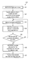
- FIG. 3 shows a program workflow diagram of a method according to the invention.
- FIG. 1 shows a schematic representation of a magnetic resonance system 5 (a magnetic resonance imaging or magnetic resonance tomography apparatus).
- a basic field magnet 1 thereby generates a temporally constant, strong magnetic field for polarization or alignment of the nuclear spins in an examination region of a subject O, for example a part of a human body that is to be examined which, resting on a table 23 , is slid into the magnetic resonance system 5 .
- the high homogeneity of the basic magnetic field that is required for nuclear magnetic resonance measurement is defined in a typical spherical measurement volume M into which the parts of the human body that are to be examined are introduced.
- shim plates made of ferromagnetic material can be attached at suitable points. Temporally variable influences can be eliminated by shim coils 2 and a suitable amplifier 27 for the shim coils 2 .
- a cylindrical gradient coil system 3 which consists of three partial windings is inserted into the basic field magnet 1 .
- Each partial winding is supplied by a corresponding amplifier 24 - 26 with current to generate a linear gradient field in the respective direction of the Cartesian coordinate system.
- the first partial winding of the gradient field system 3 thereby generates a gradient G x in the x-direction; the second partial winding generates a gradient G y in the y-direction; and the third partial winding generates a gradient G z in the z-direction.
- the amplifier 24 - 26 has a digital/analog converter (DAC) which is activated by a sequence controller 18 for time-accurate generation of gradient pulses.
- DAC digital/analog converter
- a radio-frequency antenna 4 which converts the radio-frequency pulses emitted by a radio-frequency power amplifier into an alternating magnetic field for the excitation of the nuclei and alignment of the nuclear spins of the subject to be examined or of the region of the subject that is to be examined.
- the radio-frequency antenna 4 consists of one or more RF transmission coils and multiple RF reception coils in the form of an annular, linear or matrix-like arrangement of component coils, for example.
- the radio-frequency system 22 furthermore comprises a transmission channel 9 in which the radio-frequency pulses are generated for the excitation of the nuclear magnetic resonance. Based on a pulse sequence provided by the system computer 20 , the respective radio-frequency pulses are thereby digitally represented in the sequence controller 18 as a series of complex numbers.
- This number sequence is supplied as real part and imaginary part to a digital/analog converter (DAC) in the radio-frequency system 22 via an input 12 , and from said radio-frequency system 22 to a transmission channel 9 .
- DAC digital/analog converter
- the pulse sequences are modulated on a radio-frequency carrier signal whose basic frequency corresponds to the resonance frequency of the nuclear spins in the measurement volume.
- the modulated pulse sequences are supplied via an amplifier 28 to the RE transmission coil of the radio-frequency antenna 4 .
- the switching over from transmission operation to reception operation takes place via a transmission/reception diplexer 6 .
- the RF transmission coils of the radio-frequency antenna 4 radiates the radio-frequency pulses to excite the spins in the measurement volume M, and resulting echo signals are scanned via the RF reception coils.
- the correspondingly acquired nuclear magnetic resonance signals can be phase-sensitively demodulated at an intermediate frequency in a first demodulator 8 ′ of the reception channel of the radio-frequency system 22 and digitized in the analog/digital converter (ADC). This signal is further demodulated to a frequency of 0.
- ADC analog/digital converter
- the demodulation to a frequency of 0 and the division into real part and imaginary part occur after the digitization in the digital domain in a second demodulator 8 which outputs the demodulated data via outputs 11 to an image computer 17 .
- An MR image is reconstructed by the image computer 17 from the measurement data acquired in such a manner.
- the administration of the measurement data, the image data and the control programs takes place via the system computer 20 .
- the sequence controller 18 monitors the generation of the respective desired pulse sequences and the corresponding scanning of k-space. In particular, the sequence controller 18 controls the time-accurate switching of the gradients, the emission of the radio-frequency pulses with defined phase amplitude and the reception of the nuclear magnetic resonance signals.
- the time base for the radio-frequency system 22 and the sequence controller 18 is provided by a synthesizer 19 .
- the selection of corresponding control programs for the generation of an MR image and the presentation of the generated MR image take place through a terminal 13 which comprises a keyboard 15 , a mouse 16 and a screen 14 .
- an arrangement of multiple coils is typically used. These coils—known as component coils—are connected to what is known as a coil array and arranged so as to be mutually adjacent or overlapping, so adjoining, overlapping coil images can likewise be acquired. In order to not extend the acquisition time while simultaneously improving the signal-to-noise ratio, the coils of a coil array receive simultaneously. Since the phase coding takes a lot of time in comparison to other spatial codings, partially parallel acquisition (PPA) is based on a reduction of the number of time-consuming phase coding steps.
- the k-space data are acquired with a linear arrangement of component coils (the coil array), for example, instead of a single coil.
- the coil array carries certain spatial information which is used in order to achieve a complete spatial coding via a combination of the simultaneously acquired coil data. This means that multiple lines offset in k-space that were not scanned can be reconstructed from one k-space line.
- Partially parallel acquisition thus uses spatial information that is contained in the components of a coil arrangement in order to partially replace the phase coding that is normally generated using a phase coding gradient.
- the image measurement time is thereby reduced corresponding to the ratio of the number of fines of the reduced (incomplete) data set to the number of lines of the conventional (thus complete) data set.
- the reconstruction method for example an algebraic method—requires additional calibration data points that are added to the actual measurement data and on the basis of which a reduced data set can only be completed again at all.
- Corresponding PPA techniques are known in the prior art SENSE (Sensitive Encoding) and GRAPPA (Generalized Autocalibrating Partially Parallel Acquisition), for example, and are therefore not explained in detail here.
- FIG. 2 Shown in this regard in FIG. 2 are temporal curves representing RF transmission, data sampling (ADC) and gradient switching in multiple lines 201 - 206 .
- a workflow diagram 300 which depicts the individual steps to implement the method is shown in FIG. 3 .
- the trigger point in time can comprise a heartbeat trigger which is derived from a heartbeat of a patient to be examined or a breathing trigger which is derived from the breathing of the patient to be examined, for example.
- the heartbeat trigger can be provided with the aid of an electrocardiogram monitor (EKG monitor), for example.
- the breathing trigger can be provided with the aid of what is known as a breathing pillow, for example, or be determined on the basis of rapidly measured MR profiles.
- a signal curve of a breathing curve 207 (what is known as an inspiration-expiration curve) as it can be detected with the aid of a breathing pillow, for example, is shown in the first line 201 of FIG. 2 .
- the image data of the magnetic resonance exposure should be acquired during the expiration, for example.
- a specific level 208 is therefore defined, and a trigger signal 209 - 213 is always released precisely when the breathing curve 207 crosses the predetermined level 208 upon exhaling.
- magnetic resonance data are then acquired in that magnetic field gradients are generated in the three spatial directions X (line 204 ), Y (line 205 ) and Z (line 206 ); radio-frequency signals (line 203 ) are radiated into the measurement volume M via the radio-frequency antenna 4 to excite the nuclear spins; and corresponding nuclear magnetic resonance signals 219 - 223 (line 202 ) are received with the component coils of the radio-frequency antenna 4 .
- calibration data 219 in k-space are detected with each component coil (Step 302 ).
- multiple reference lines in k-space are acquired with each component coil.
- the reference lines are acquired in specific central regions of k-space.
- the signal curves shown in lines 202 - 206 are in particular only schematically depicted during the time periods 214 - 218 . In reality the signal curves that are shown flat correspond to a plurality of signal changes that, however, run so quickly that they cannot be depicted at the shown resolution of FIG. 2 .
- the upper and lower edges of the flat signal curves thus represent envelopes of the actual, real signal curves.
- Individual MR acquisitions are visible outside of the time periods 214 - 218 , i.e. in particular respectively before the corresponding time periods. These represent examples of MR navigators.
- the breathing state can be determined via the diaphragm position from the profile of the navigators.
- Step 302 the process waits for the next trigger point in time 210 (Step 303 ).
- the second time period 215 during the second exhalation phase of the patient follows the second trigger point in time 210 .
- a data set 220 in k-space is acquired with the component coils (Step 304 ).
- the data set 220 acquired in the second time period 215 can comprise a complete or incomplete k-space slice, for example. Since in the present example a 3-dimensional image measurement should be implemented, additional data sets 221 - 223 are acquired in additional time periods 216 - 218 (comparable to the acquisition in the second time period 215 ).
- the time periods 216 - 218 are respectively defined via corresponding trigger points in time 211 - 213 .
- Complete or incomplete data sets 221 - 223 for additional k-space slices of the examination subject can respectively be acquired in turn in the additional time periods 216 - 218 . This is continued until a sufficient quantity of data sets 220 - 223 has been acquired (Step 305 ).
- a complete data set is reconstructed from the acquired data sets 220 - 223 in Step 306 using the calibration data acquired in the time period 214 .
- the missing data can be completed by combining the present data with the calibration data.
- Step 307 the complete 3-dimensional data set is then transformed into a corresponding image data set.
- a portion of k-space is respectively acquired after the trigger 210 - 213 . Since the reference data are acquired in a separate expiration phase 214 and not together with the image measurement in the time periods 215 - 218 , more time is provided for the acquisition of the image data in the time periods 215 - 218 so that movement artifacts can be reduced or the resolution of the image measurement can be reduced or the resolution of the image measurement can be increased. A coherency of the reference data and the actual image measurement is ensured by the triggering of both the acquisition of the calibration data and the acquisition of the image data.
- a 3D image measurement based on a partially parallel acquisition was described.
- the present invention is not limited to 3D image measurements; rather, it can also be comparably used for 2D image measurements.
- 3D image measurements for this in the first time period 215 an incomplete data set can be acquired which is then completed via reconstruction with the aid of the calibration data. The additional measurements in the time periods 216 - 218 are then unnecessary.
- k-space can be incompletely acquired in multiple time periods 215 - 218 , and in a subsequent reconstruction a complete 2D data set can be generated from the incomplete data sets and the calibration data.
Landscapes
- Physics & Mathematics (AREA)
- Health & Medical Sciences (AREA)
- General Health & Medical Sciences (AREA)
- Nuclear Medicine, Radiotherapy & Molecular Imaging (AREA)
- Radiology & Medical Imaging (AREA)
- Engineering & Computer Science (AREA)
- Signal Processing (AREA)
- High Energy & Nuclear Physics (AREA)
- Condensed Matter Physics & Semiconductors (AREA)
- General Physics & Mathematics (AREA)
- Magnetic Resonance Imaging Apparatus (AREA)
Abstract
Description
Claims (10)
Applications Claiming Priority (3)
| Application Number | Priority Date | Filing Date | Title |
|---|---|---|---|
| DE102010032080 | 2010-07-23 | ||
| DE102010032080.3 | 2010-07-23 | ||
| DE201010032080 DE102010032080B4 (en) | 2010-07-23 | 2010-07-23 | Triggered Magnetic Resonance Imaging Based on Partial Parallel Acquisition (PPA) |
Publications (2)
| Publication Number | Publication Date |
|---|---|
| US20120019246A1 US20120019246A1 (en) | 2012-01-26 |
| US8854040B2 true US8854040B2 (en) | 2014-10-07 |
Family
ID=45443472
Family Applications (1)
| Application Number | Title | Priority Date | Filing Date |
|---|---|---|---|
| US13/187,692 Active 2032-12-19 US8854040B2 (en) | 2010-07-23 | 2011-07-21 | Method for magnetic resonance imaging based on partially parallel acquisition (PPA) |
Country Status (2)
| Country | Link |
|---|---|
| US (1) | US8854040B2 (en) |
| DE (1) | DE102010032080B4 (en) |
Cited By (4)
| Publication number | Priority date | Publication date | Assignee | Title |
|---|---|---|---|---|
| US20120299590A1 (en) * | 2011-05-27 | 2012-11-29 | Riederer Stephen J | Method for Self-Calibrated Parallel Magnetic Resonance Image Reconstruction |
| US20130278263A1 (en) * | 2010-12-22 | 2013-10-24 | Koninklijke Philips Electronics N.V. | Parallel mri method using calibration scan, coil sensitivity maps and navigators for rigid motion compensation |
| US20140117985A1 (en) * | 2012-10-31 | 2014-05-01 | David Grodzki | Method and magnetic resonance apparatus to generate raw data sets from double echo data acquisitions |
| US10386443B2 (en) * | 2017-06-13 | 2019-08-20 | Siemens Healthcare Gmbh | Method for calibration in a magnetic resonance imaging procedure |
Families Citing this family (9)
| Publication number | Priority date | Publication date | Assignee | Title |
|---|---|---|---|---|
| AU2010273298B2 (en) * | 2009-07-15 | 2014-10-23 | Viewray Technologies, Inc. | Method and apparatus for shielding a linear accelerator and a magnetic resonance imaging device from each other |
| US8970217B1 (en) | 2010-04-14 | 2015-03-03 | Hypres, Inc. | System and method for noise reduction in magnetic resonance imaging |
| US8885904B2 (en) * | 2012-04-19 | 2014-11-11 | General Electric Company | Systems and methods for landmark correction in magnetic resonance imaging |
| US9889318B2 (en) | 2012-10-26 | 2018-02-13 | Viewray Technologies, Inc. | Assessment and improvement of treatment using imaging of physiological responses to radiation therapy |
| US9446263B2 (en) | 2013-03-15 | 2016-09-20 | Viewray Technologies, Inc. | Systems and methods for linear accelerator radiotherapy with magnetic resonance imaging |
| DE102016200889B4 (en) * | 2016-01-22 | 2018-02-08 | Siemens Healthcare Gmbh | Reconstruction of image data |
| EP3423153B1 (en) | 2016-03-02 | 2021-05-19 | ViewRay Technologies, Inc. | Particle therapy with magnetic resonance imaging |
| JP7127126B2 (en) | 2017-12-06 | 2022-08-29 | ビューレイ・テクノロジーズ・インコーポレイテッド | Radiation therapy system, method and software |
| US11995791B2 (en) | 2021-07-30 | 2024-05-28 | Halliburton Energy Services, Inc. | Generating a complete borehole image using transformation |
Citations (7)
| Publication number | Priority date | Publication date | Assignee | Title |
|---|---|---|---|---|
| US6144201A (en) | 1997-12-26 | 2000-11-07 | Kabushiki Kaisha Toshiba | MR imaging utilizing ECG gating technique |
| US6268730B1 (en) | 1999-05-24 | 2001-07-31 | Ge Medical Systems Global Technology Company Llc | Multi-slab multi-window cardiac MR imaging |
| US20050134272A1 (en) | 2003-12-01 | 2005-06-23 | Roberts Timothy P.L. | Device for enabling reduced motion-related artifacts in parallel magnetic resonance imaging |
| US20080303521A1 (en) | 2007-06-08 | 2008-12-11 | Philip James Beatty | System and method for accelerated magnetic resonance parallel imaging |
| US7609058B2 (en) * | 2006-11-17 | 2009-10-27 | Siemens Medical Solutions Usa, Inc. | Method and apparatus for generating a magnetic resonance data file |
| US7649354B2 (en) * | 2007-09-26 | 2010-01-19 | General Electric Co. | Method and apparatus for acquiring magnetic resonance imaging data |
| US8073522B2 (en) * | 2006-07-21 | 2011-12-06 | Siemens Aktiengesellschaft | Method and magnetic resonance apparatus for dynamic magnetic resonance imaging |
-
2010
- 2010-07-23 DE DE201010032080 patent/DE102010032080B4/en not_active Expired - Fee Related
-
2011
- 2011-07-21 US US13/187,692 patent/US8854040B2/en active Active
Patent Citations (7)
| Publication number | Priority date | Publication date | Assignee | Title |
|---|---|---|---|---|
| US6144201A (en) | 1997-12-26 | 2000-11-07 | Kabushiki Kaisha Toshiba | MR imaging utilizing ECG gating technique |
| US6268730B1 (en) | 1999-05-24 | 2001-07-31 | Ge Medical Systems Global Technology Company Llc | Multi-slab multi-window cardiac MR imaging |
| US20050134272A1 (en) | 2003-12-01 | 2005-06-23 | Roberts Timothy P.L. | Device for enabling reduced motion-related artifacts in parallel magnetic resonance imaging |
| US8073522B2 (en) * | 2006-07-21 | 2011-12-06 | Siemens Aktiengesellschaft | Method and magnetic resonance apparatus for dynamic magnetic resonance imaging |
| US7609058B2 (en) * | 2006-11-17 | 2009-10-27 | Siemens Medical Solutions Usa, Inc. | Method and apparatus for generating a magnetic resonance data file |
| US20080303521A1 (en) | 2007-06-08 | 2008-12-11 | Philip James Beatty | System and method for accelerated magnetic resonance parallel imaging |
| US7649354B2 (en) * | 2007-09-26 | 2010-01-19 | General Electric Co. | Method and apparatus for acquiring magnetic resonance imaging data |
Non-Patent Citations (5)
| Title |
|---|
| "Dynamic Autocalibrated Parallel Imaging Using Temporal GRAPPA (TGRAPPA)", Breuer et al., Magnetic Resonance in Medicine, vol. 53 (2005) pp. 981-985. |
| "Generalized Autocalibrating Partially Parallel Acquisitions (GRAPPA)", Griswold et al., Magnetic Resonance in Medicine, vol. 47 (2002) pp. 1202-1210. |
| "Moderne Leberbildgebung mit der MRT," Zech et al., Der Radiologe, vol. 12 (2004) pp. 1160-1169. |
| "SENSE: Sensitivity Encoding for Fast MRI", Pruessmann et al., Magnetic Resonance in Medicine, vol. 42 (1999) pp. 952-962. |
| "Simultaneous Acquisition of Spatial Harmonics (SMASH): Fast Imaging with Radiofrequency Coil Arrays", Sodickson et al., Magnetic Resonance in Medicine, vol. 38 (1997) pp. 591-603. |
Cited By (7)
| Publication number | Priority date | Publication date | Assignee | Title |
|---|---|---|---|---|
| US20130278263A1 (en) * | 2010-12-22 | 2013-10-24 | Koninklijke Philips Electronics N.V. | Parallel mri method using calibration scan, coil sensitivity maps and navigators for rigid motion compensation |
| US10067213B2 (en) * | 2010-12-22 | 2018-09-04 | Koninklijke Philips N.V. | Parallel MRI method using calibration scan, coil sensitivity maps and navigators for rigid motion compensation |
| US20120299590A1 (en) * | 2011-05-27 | 2012-11-29 | Riederer Stephen J | Method for Self-Calibrated Parallel Magnetic Resonance Image Reconstruction |
| US9018952B2 (en) * | 2011-05-27 | 2015-04-28 | Mayo Foundation For Medical Education And Research | Method for self-calibrated parallel magnetic resonance image reconstruction |
| US20140117985A1 (en) * | 2012-10-31 | 2014-05-01 | David Grodzki | Method and magnetic resonance apparatus to generate raw data sets from double echo data acquisitions |
| US9506998B2 (en) * | 2012-10-31 | 2016-11-29 | Siemens Aktiengesellschaft | Method and magnetic resonance apparatus to generate raw data sets from double echo data acquisitions |
| US10386443B2 (en) * | 2017-06-13 | 2019-08-20 | Siemens Healthcare Gmbh | Method for calibration in a magnetic resonance imaging procedure |
Also Published As
| Publication number | Publication date |
|---|---|
| US20120019246A1 (en) | 2012-01-26 |
| DE102010032080B4 (en) | 2012-09-27 |
| DE102010032080A1 (en) | 2012-01-26 |
Similar Documents
| Publication | Publication Date | Title |
|---|---|---|
| US8854040B2 (en) | Method for magnetic resonance imaging based on partially parallel acquisition (PPA) | |
| US8878533B2 (en) | Magnetic resonance method and system to generate an image data set | |
| US8643365B2 (en) | Method and magnetic resonance system to generate magnetic resonance images | |
| US10185013B2 (en) | Magnetic resonance imaging (MRI) apparatus and method of generating MR image | |
| US9829553B2 (en) | Method and magnetic resonance system for functional MR imaging of a predetermined volume segment of the brain of a living examination subject | |
| KR101629165B1 (en) | Magnetic resonance imaging apparatus and controlling | |
| US9320454B2 (en) | Method and magnetic resonance apparatus to generate a series of MR images to monitor a position of an interventional device | |
| US6828788B2 (en) | Apparatus and method for magnetic resonance imaging using partial parallel acquisition (PPA) | |
| US10209336B2 (en) | Method and magnetic resonance apparatus for the acquisition of calibration data using simultaneous echo refocusing | |
| US8818491B2 (en) | System for non-contrast enhanced MR anatomical imaging | |
| US9618598B2 (en) | Magnetic resonance method, apparatus and radiofrequency coil for acquiring magnetic resonance data of at least one tooth | |
| US9566014B2 (en) | System for cardiac MR and MR cine imaging using parallel image processing | |
| US20120126813A1 (en) | Method and magnetic resonance system to acquire mr data in a predefined three-dimensional volume segment | |
| US9684049B2 (en) | Magnetic resonance method and apparatus for correction of magnetic resonance data | |
| US10962617B2 (en) | Methods and apparatus for scan time reductions in magnetic resonance imaging using outer volume supression | |
| US9354290B2 (en) | Method and magnetic resonance system to generate an MR image with a tracking factor | |
| KR101629162B1 (en) | Magnetic resonance imaging apparatus and controlling | |
| US9678188B2 (en) | Magnetic resonance system and method to acquire at least two measurement data sets from an examination subject | |
| US9535149B2 (en) | Method and apparatus for acquisition of magnetic resonance data | |
| US9506999B2 (en) | Method and magnetic resonance system to generate raw data sets in a double echo acquisition sequence | |
| US20100045292A1 (en) | Magnetic resonance angiography method and apparatus | |
| US9506998B2 (en) | Method and magnetic resonance apparatus to generate raw data sets from double echo data acquisitions | |
| US10054656B2 (en) | Method and apparatus that acquire magnetic resonance data using a 3D turbo or fast spin echo pulse sequence with a lengthened echo spacing | |
| US9823321B2 (en) | Method and apparatus for acquisition of magnetic resonance data with fat saturation pulses radiated with respectively different flip angles | |
| US9615769B2 (en) | Method to generate an RF excitation pulse to excite an arbitrarily shaped volume, method for targeted excitation of spins within a vessel, and method to create MR angiography images, and magnetic resonance system |
Legal Events
| Date | Code | Title | Description |
|---|---|---|---|
| AS | Assignment |
Owner name: SIEMENS AKTIENGESELLSCHAFT, GERMANY Free format text: ASSIGNMENT OF ASSIGNORS INTEREST;ASSIGNORS:KANNENGIESSER, STEPHAN;RUFF, JAN;SIGNING DATES FROM 20110721 TO 20110725;REEL/FRAME:026988/0200 |
|
| STCF | Information on status: patent grant |
Free format text: PATENTED CASE |
|
| AS | Assignment |
Owner name: SIEMENS HEALTHCARE GMBH, GERMANY Free format text: ASSIGNMENT OF ASSIGNORS INTEREST;ASSIGNOR:SIEMENS AKTIENGESELLSCHAFT;REEL/FRAME:039271/0561 Effective date: 20160610 |
|
| MAFP | Maintenance fee payment |
Free format text: PAYMENT OF MAINTENANCE FEE, 4TH YEAR, LARGE ENTITY (ORIGINAL EVENT CODE: M1551) Year of fee payment: 4 |
|
| MAFP | Maintenance fee payment |
Free format text: PAYMENT OF MAINTENANCE FEE, 8TH YEAR, LARGE ENTITY (ORIGINAL EVENT CODE: M1552); ENTITY STATUS OF PATENT OWNER: LARGE ENTITY Year of fee payment: 8 |
|
| AS | Assignment |
Owner name: SIEMENS HEALTHINEERS AG, GERMANY Free format text: ASSIGNMENT OF ASSIGNORS INTEREST;ASSIGNOR:SIEMENS HEALTHCARE GMBH;REEL/FRAME:066088/0256 Effective date: 20231219 |
|
| AS | Assignment |
Owner name: SIEMENS HEALTHINEERS AG, GERMANY Free format text: CORRECTIVE ASSIGNMENT TO CORRECT THE ASSIGNEE PREVIOUSLY RECORDED AT REEL: 066088 FRAME: 0256. ASSIGNOR(S) HEREBY CONFIRMS THE ASSIGNMENT;ASSIGNOR:SIEMENS HEALTHCARE GMBH;REEL/FRAME:071178/0246 Effective date: 20231219 |