US8852359B2 - Method of bonding a metal to a substrate - Google Patents
Method of bonding a metal to a substrate Download PDFInfo
- Publication number
- US8852359B2 US8852359B2 US13/310,110 US201113310110A US8852359B2 US 8852359 B2 US8852359 B2 US 8852359B2 US 201113310110 A US201113310110 A US 201113310110A US 8852359 B2 US8852359 B2 US 8852359B2
- Authority
- US
- United States
- Prior art keywords
- oxide
- metal
- substrate
- magnesium
- over
- Prior art date
- Legal status (The legal status is an assumption and is not a legal conclusion. Google has not performed a legal analysis and makes no representation as to the accuracy of the status listed.)
- Expired - Fee Related, expires
Links
Images


Classifications
-
- B—PERFORMING OPERATIONS; TRANSPORTING
- B22—CASTING; POWDER METALLURGY
- B22D—CASTING OF METALS; CASTING OF OTHER SUBSTANCES BY THE SAME PROCESSES OR DEVICES
- B22D19/00—Casting in, on, or around objects which form part of the product
- B22D19/08—Casting in, on, or around objects which form part of the product for building-up linings or coverings, e.g. of anti-frictional metal
-
- C—CHEMISTRY; METALLURGY
- C23—COATING METALLIC MATERIAL; COATING MATERIAL WITH METALLIC MATERIAL; CHEMICAL SURFACE TREATMENT; DIFFUSION TREATMENT OF METALLIC MATERIAL; COATING BY VACUUM EVAPORATION, BY SPUTTERING, BY ION IMPLANTATION OR BY CHEMICAL VAPOUR DEPOSITION, IN GENERAL; INHIBITING CORROSION OF METALLIC MATERIAL OR INCRUSTATION IN GENERAL
- C23C—COATING METALLIC MATERIAL; COATING MATERIAL WITH METALLIC MATERIAL; SURFACE TREATMENT OF METALLIC MATERIAL BY DIFFUSION INTO THE SURFACE, BY CHEMICAL CONVERSION OR SUBSTITUTION; COATING BY VACUUM EVAPORATION, BY SPUTTERING, BY ION IMPLANTATION OR BY CHEMICAL VAPOUR DEPOSITION, IN GENERAL
- C23C6/00—Coating by casting molten material on the substrate
Definitions
- the present disclosure relates generally to methods of bonding a metal to a substrate.
- automotive parts are fabricated from, for example, aluminum or steel.
- a lighter-weight material such as magnesium.
- the presence of the lighter-weight material may, in some cases, reduce the overall weight of the automotive part.
- a method of bonding a metal to a substrate involves forming an oxide layer on a surface of the substrate, and in a molten state, over-casting the metal onto the substrate surface.
- the over-casting drives a reaction at an interface between the over-cast metal and the oxide layer to form another oxide, where the other oxide binds the metal to the substrate surface upon solidification of the over-cast metal.
- FIGS. 1A through 1F schematically depict one example of a method of bonding a metal to a substrate
- FIGS. 1A through 1D (with or without FIG. 1C) and 1J schematically depict other examples of a method of bonding a metal to a substrate;
- FIGS. 1A , 1 B, and 1 D through 1 F schematically depict yet another example of a method of bonding a metal to a substrate
- FIGS. 1A and 1G through 1 I schematically depict still another example of a method of bonding a metal to a substrate
- FIG. 1F-A is an enlarged view of a portion of the schematic shown in FIG. 1F ;
- FIG. 2B is a plan view of the plurality of nano-pores shown in FIG. 2A .
- Aluminum and steel may be used to make various automotive parts, at least because these materials have a mechanical strength that contributes to the structural integrity of the part. It has been found that some of the aluminum or steel in a part may be replaced by lighter-weight material(s) (such as, e.g., magnesium). It is believed that the presence of the lighter-weight material(s) may, in some instances, reduce the overall weight of the automotive part.
- lighter-weight material(s) such as, e.g., magnesium
- magnesium may be incorporated onto an aluminum or steel part via a casting process, such as a process known as over-casting. It has also been found that, in some instances, the magnesium may not metallurgically bond to the underlying aluminum or steel, at least not to the extent necessary to form a part that is considered to be structurally sound and usable in an automobile.
- the aluminum may include a dense oxide surface layer (e.g., alumina) formed thereon which, during casting, may prevent magnesium from metallurgically bonding to the aluminum underneath the oxide layer. More specifically, during the casting process, magnesium cannot penetrate the dense oxide layer and bond with the underlying aluminum in a manner sufficient to render the resulting part as structurally sound.
- a part that is “structurally sound” is one that has mechanical properties that enable the part to withstand various operating stresses and strains incurred during use of the part.
- Example(s) of the method disclosed herein may be used to form a part by bonding a metal (such as magnesium or magnesium alloys) to a substrate (such as aluminum, steel, titanium, etc.).
- a metal such as magnesium or magnesium alloys
- a substrate such as aluminum, steel, titanium, etc.
- the joint created between these materials is such that the part is considered to have the structural integrity necessary so that the part can be used in an automobile.
- the two materials may be joined together by improving the joint strength at an interface (i.e., its interfacial strength) between the metal and the substrate. This may be accomplished by altering the substrate surface in a manner suitable to promote a desired chemical reaction.
- the joint strength may be improved by oxidizing the surface of the substrate, and forcing a chemical reaction between the metal and the oxidized surface to produce another oxide that enables the metal to chemically bond to the oxidized surface.
- a physical bond may also form, such as a mechanical interlock created between the metal and the surface of the substrate.
- the part 10 which is formed by the method, includes an aluminum substrate and a magnesium metal bonded thereto. It is to be understood that the method may also or otherwise be used to form parts made from other combinations of materials.
- the part may be formed from substrate materials that may suitably be used for automotive applications (e.g., to make an automotive chassis component, an engine cradle, an instrument panel (IP) beam, an engine block, and/or the like).
- the substrate may, in some cases, be chosen from materials that are refractory enough so that the substrate material does not melt when exposed to the molten metal during over-casting, details of which will be provided below at least in conjunction with FIG. 1D .
- the substrate materials may be chosen from a metal.
- the metal may be chosen from aluminum, titanium, and alloys thereof which may form a porous oxide structure when anodized (described further below).
- the metal may be chosen from copper, nickel, and alloys thereof which may form a porous oxide structure when exposed to an oxidizing technique other than anodization (also described further below).
- the substrate material may otherwise be chosen from a material to make a part that is suitable for use in other applications, such as non-automotive applications including aircraft, tools, housing/building components (e.g., pipes), etc.
- the substrate material may be chosen from any of the metals listed above, or may be chosen from another metal or non-metal (e.g., steel, cast iron, ceramics, high melting temperature polymers (such as, e.g., crystal polymers, polyimides, polyether imides, polysulfones, and/or other polymers having a melting temperature of at least 350° C.), etc.).
- the high melting temperature polymers may further include a protective layer and/or be cooled to prevent the polymer from melting and/or decomposing so that the combination of the polymer, protective layer, and the over-casting process does not significantly damage the substrate (i.e., the article formed by the substrate/over-cast metal system is still functional for its intended purpose).
- the substrate material may, in an example, be aluminized (i.e., the formation of an aluminum or aluminum-rich alloy layer on the surface of the substrate material) to be used in the method disclosed herein.
- steel may be aluminized via hot-dipping the steel in an aluminum-silicon melt, which forms an aluminum layer on the steel surface. This aluminum layer may later be anodized to form alumina, as described in detail below.
- other materials e.g., copper, may also be aluminized via hot-dipping or another suitable method such as, e.g., vapor deposition.
- an alumina surface may not be required to perform examples of the method disclosed herein.
- magnesium or another metal may be oxidized to form an oxide layer and, if desired, pores may be formed therein. Therefore, other systems may be used beyond over-casting magnesium onto aluminum or an aluminized surface.
- Other methods of forming a porous substrate surface are also contemplated herein, and are considered to be within the purview of the instant disclosure.
- One way of forming the oxide structure is to deposit the oxide onto the surface of the substrate. This may be accomplished, for example, by electroplating another oxidizable metal onto the substrate surface, and then oxidizing the other metal.
- Still other methods include chemical vapor deposition, physical vapor deposition, thermal spraying, and a dipping process.
- the dipping process may involve dipping the substrate 12 into a molten metal to create a thin metal layer on the surface S, and then oxidizing the metal.
- Examples of other methods of forming pores in the oxidized substrate surface include electroplating, electro-discharge, a process utilizing a laser, and/or shot blasting with or in an oxide environment.
- the pores may then be formed in the oxide (to form the oxide structure) via electro-discharge using a suitable electrode in an oxide environment.
- electroplating is used as a way of creating a porous surface, the porosity of the surface may be controlled using a patterning and/or masking process (such as lithography), sputtering of non-conductive materials, etc.
- the metal to be bonded to the substrate may be chosen from any metal in the periodic table of elements that has a melting point or temperature that is lower than, or near (e.g., within 1° C. of) the melting temperature of the substrate to which metal is bonded. It is to be understood that the over-cast metals discussed herein may be the pure metal or an alloy thereof. Further, the substrate should be refractory enough so that it does not melt too severely during casting. It has been found that selecting metals having a lower melting point than the substrate enables casting to be accomplished without melting the underlying substrate.
- magnesium may be selected as a metal to be over-cast on any of the substrate materials listed above (e.g., aluminum, titanium, copper, alloys thereof, etc., except for, in some instances, magnesium), at least in part because the melting temperature of magnesium is about 639° C. and is lower than any of these substrate materials.
- Some examples of combinations of the metal and substrate that may be used to form an automotive part include i) magnesium and aluminum, respectively, and ii) magnesium and steel, respectively.
- Other examples of metals that may be chosen include aluminum, copper, zinc, titanium, iron, and alloys thereof. If aluminum is selected as the metal, the aluminum may be bonded to substrate materials having a melting temperature that is lower than aluminum.
- aluminum which has a melting temperature of about 660° C.
- copper which has a melting temperature of about 1083° C.
- titanium which has a melting temperature of about 1660° C.
- steel e.g., stainless steel has a melting temperature of about 1510° C. and carbon steel has a melting temperature ranging from about 1425° C. to about 1540° C.
- copper which has a melting temperature of about 1083° C.
- titanium which has a melting temperature of about 1660° C.
- steel e.g., stainless steel has a melting temperature of about 1510° C. and carbon steel has a melting temperature ranging from about 1425° C. to about 1540° C.
- copper may be bonded to steel at least in part because copper has a lower melting temperature than steel.
- the melting temperature of the over-casting metal does not have to be less than the substrate, at least in part because the substrate may include a protective layer, be subjected to cooling, and/or have a mass and conductivity that is sufficient to extract the heat of solidification before melting.
- the substrate may include a protective layer, be subjected to cooling, and/or have a mass and conductivity that is sufficient to extract the heat of solidification before melting.
- aluminum (again, which has a melting temperature of about 660° C. may be over-cast on magnesium (which has a melting temperature of about 639° C.) if the over-casting is performed, e.g., in a die caster with a cooling mechanism to cool the magnesium.
- the over-cast metal may otherwise be selected from a metal that has a higher melting temperature than the substrate.
- the substrate material may be cooled during the over-casting, and/or have a mass that is sufficient so that the molten over-cast metal solidifies before the metal deleteriously affects the structural integrity of the substrate, and/or have a protective layer thereon.
- the heat transfer to the substrate may be low enough so that the temperature of the substrate does not reach its melting temperature, and thus will not melt (or melts slightly).
- a coating made from a material that has, e.g., a very high melting temperature (e.g., alumina) may be established on the substrate that can reduce the heat transfer to the substrate.
- alumina which has a melting temperature of about 2072° C.
- the coating material selected should also be durable and adherent so that the material can contribute to the structural integrity of the formed part.
- a material that may be deficient in durability and adhesion may be used as a coating so long as the material is combined with suitable additional components to increase its durability and adhesion.
- the substrate when the metal is magnesium, the substrate may be chosen from aluminum, titanium, manganese, chromium, zinc, iron, copper, and alloys thereof.
- the over-cast metals there is a hierarchy of the over-cast metals, where a metal positioned at a higher position on the list can thermodynamically reduce the oxide of the metal positioned lower on the list.
- This list which includes the highest metal position first and the lowest metal position last, includes: magnesium, lithium, aluminum, titanium, silicon, vanadium, manganese, chromium, sodium, zinc, potassium, phosphorus, tin, iron, nickel, cobalt, and copper.
- aluminum may be over-cast on titanium oxide; but cannot be effectively over-cast on magnesium oxide (i.e., a desirable reaction between the materials will not occur).
- the silicon identified in the list above may, in some instances, be used in an alloy such as, e.g., an aluminum-silicon alloy having an aluminum and silicon eutectic structure. Oxidation of the aluminum-silicon alloy may create a structure including oxides of aluminum and oxides of silicon.
- the substrate material is specifically chosen from aluminum or aluminum alloys and the bonding metal is chosen from magnesium or magnesium alloys.
- the bonding metal is chosen from magnesium or magnesium alloys.
- a part is formed including an aluminum substrate and magnesium bonded thereto.
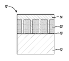
- the example of the method depicted in FIGS. 1A-1F generally involves selecting a substrate 12 (shown in FIG. 1A ), and then oxidizing the surface S of the substrate 12 to form an oxide layer (identified by reference character 18 in FIG. 1B ). After the surface S is oxidized, upon introducing an over-cast metal (identified by reference character M in FIG. 1D ), a reaction occurs at an interface (e.g., I 1 , I 2 shown in FIG. 1D ) formed between an over-cast metal M and the metal oxide layer 18 formed on the substrate surface S.
- the foregoing reaction(s) forms another oxide, which is an intermediate product (shown, e.g., as layer 20 in FIGS.
- the oxide layer 18 is a porous oxide layer, and the layer 18 may be formed by growing the oxide layer 18 on the substrate surface S via an anodization process.
- anodization is the oxidation of a portion of the aluminum substrate 12 to form the structure 18 made of aluminum oxide (i.e., alumina).
- a portion of the aluminum substrate 12 is consumed as the aluminum oxide structure 18 grows.
- Anodization may be accomplished, for instance, by employing the aluminum substrate 12 as the anode of an electrolytic cell, and placing the anode and a suitable cathode in an aqueous electrolyte.
- electrolyte examples include sulfuric acid (H 2 SO 4 ), phosphoric acid (H 2 PO 4 ), oxalic acid (C 2 H 2 O 4 ), and chromic acid (H 2 CrO 4 ).
- These electrolytes desirably form porous alumina; i.e., an alumina structure 18 including the nano-pores 16 formed therein.
- any suitable cathode may be used, examples of which may include aluminum or lead.
- a suitable voltage and current e.g., a DC current or, in some cases, a DC component and an AC component
- the aluminum substrate is anodized depending, at least in part, on the desired thickness of the porous oxide layer to be formed. For instance, it is believed that, for anodizing using a sulfuric acid electrolyte, every 3 ⁇ m of the oxide layer that is formed consumes about 2 ⁇ m of the underlying substrate. It is further believed that the foregoing ratio may change based, at least in part, on the porosity of the anodized layer and the mass balance of the metal oxide layer and the underlying substrate.
- anodization may occur at a voltage ranging from about 1 V to about 120 V, and the voltage may be adjusted as desired throughout the anodization process as the oxide layer (or structure 18 ) grows thicker.
- the thickness of the oxide layer 18 depends, at least in part, on the current density multiplied by the anodization time. Typically, a particular voltage is applied in order to achieve the current density required to grow the oxide layer 18 to a desired thickness.
- the electrolyte used, as well as the temperature may also affect the properties of the oxide layer 18 , and the ability to grow and form the oxide layer 18 to a desired thickness.
- the thickness of the oxide layer 18 may depend on the conductivity of the electrolyte, which in turn depends on the type, concentration, and the temperature of the electrolyte.
- the oxide layer 18 is electrically insulating, and thus at a constant voltage, the current density will decrease as the layer grows. In some cases, the decrease in current density may limit the maximum growth of the oxide layer 18 , and thus the voltage cannot always be continuously increased to increase the thickness of the layer 18 . However, in some instances, it may be desirable to increase the voltage throughout the process. In one example, the voltage applied may start at about 25 V to 30 V, and then the voltage may ramp up to a higher voltage as the oxide layer 18 grows.
- the size of the nano-pores 16 may be controlled at least by adjusting the voltage, but the adjustment to the voltage may change depending on the material(s) used (e.g., the substrate material).
- nano-pores 16 have an effective diameter D (see FIG. 1F ) of about 1.29 nm per 1 V of voltage applied, and the spacing between adjacent pores 16 is about 2.5 nm per 1V of voltage applied. The pore 16 size and spacing will be described in further detail below.
- the growth of the structure 18 depends, at least in part, on current density, the chemistry of the electrolytic bath (i.e., the electrolyte), the temperature at which anodization occurs, the amount of anodization time, and/or the voltage applied.
- certain properties of the structure 18 may also be controlled by incorporating AC current in place of or superimposed onto the DC current.
- anodization may be accomplished at a temperature ranging from about ⁇ 5° C. to about 70° C. (or in another example, from about ⁇ 5° C.
- the process may take place for a few minutes up to a few hours depending, at least in part, on a desired thickness of the structure 18 to be grown.
- the thickness of the oxide layer or structure 18 grown ranges from about 2 ⁇ m to about 250 ⁇ m. In another example, the thickness of the oxide layer or structure 18 grown ranges from about 40 ⁇ m to about 80 ⁇ m.
- the porous oxide structure 18 formed via the anodization process described above may include many nano-pores 16 defined therein, and a barrier layer 19 of alumina defining the bottom of each pore 16 .
- the barrier layer 19 is a thin, dense layer (i.e., with little porosity, if at all), and may constitute about 0.1% to about 2% of the entire thickness of the oxide structure 18 formed.
- nano-pore refers to a pore having an effective diameter (knowing that each pore may not have a perfectly circular cross section) falling within the nanometer range (e.g., from 1 nm to 1000 nm); and the pore may extend at least partially through the oxide structure 18 .
- the oxide structure 18 may be etched to remove portions thereof at the bottom of the nano-pores 16 (including the barrier layer 19 ), thereby exposing the underlying aluminum substrate 12 .
- Each nano-pore 16 has a substantially cylindrical shape that extends throughout the length of the pore (as schematically shown, for example, in FIG. 2A ).
- the size of the nano-pores 16 depends, at least in part, on the anodization parameters as described above. Further, it is assumed that the effective diameter of each pore 16 is about the same, and that the effective diameter is also substantially the same throughout the length of the pore 16 . It is to be understood, however, that each nano-pore 16 may not necessarily have a diameter that is consistent throughout its length; e.g., one or more pores 16 may have a diameter that is smaller at the top of the pore 16 (e.g., the end of the pore opposed to the substrate surface S) and bigger at the bottom of the pore 16 (e.g., the end of the pore adjacent to the substrate surface S).
- the nano-pores 16 may have a bulb-like shape, where the effective diameter near the mid-point of the length of the pore 16 is larger than at both ends of the pore 16 .
- the nano-pores 16 may otherwise have another configuration not specifically mentioned here.
- the effective diameter D of each nano-pore 16 ranges from about 15 nm to about 160 nm. In another example, the effective diameter D of each nano-pore 16 ranges from about 25 nm to about 75 nm. In still another example, the effective diameter D ranges from about 50 nm to about 150 nm. It is to be understood, however, that the desired effective diameter D (or size) of the nano-pores 16 may depend, at least in part, on the fluidity, viscosity, and wettability of the molten metal M, at least in part because the molten metal M will be penetrating the nano-pore 16 .
- the size of the nano-pores 16 may also depend on whether or not the substrate surface S is wetting to the metal M (which will be described in further detail below). Generally, in instances where the surface S is wetting to the metal M, the desired size of the nano-pores 16 may be smaller than when the surface S is non-wetting to the metal M.
- the diameter of the nano-pores 16 may vary through the height of the oxide structure 18 (e.g., where the nano-pores 16 have segments with different diameters). This may be accomplished by growing the oxide layer 18 at a first voltage, where the pore 16 size attempts to reach a steady state. Then, during the process, a transition zone is created by changing the voltage so that the pores 16 attempt to reach another steady state. More specifically, the steady state diameters of the nano-pore 16 depend, at least in part, on the voltage. For instance, a first voltage may be used to grow the nano-pores 16 initially until a first steady state diameter is reached, and then a second voltage may be used for further growth of the nano-pores 16 until a second steady state diameter is reached. The transition zone of the first and second diameters of the nano-pores 16 occurs between the first and second voltages.
- a substrate surface S areas with and without nano-pores 16 may be formed. This may be accomplished using a mask.
- the mask prohibits pore formation and thus the masked areas include no nano-pores.
- These masked areas of the substrate surface S may be larger in scale (e.g., micrometers or even millimeters) than the size of the individual nano-pores 16 grown in the unmasked areas.
- this method can create discontinuous areas (i.e., nano-islands, discussed further hereinbelow) that contain nano-pores 16 or a continuous nano-pore-containing layer that has multiple holes (i.e., areas without nano-pores 16 ) formed therein.
- nano-pores 16 across the substrate surface S having different dimensions. This may be accomplished, for example, by masking a first area of the surface S, and allowing the nano-pores 16 to grow in the unmasked area while applying a suitable voltage for growth. Thereafter, the area of the substrate surface S including nano-pores 16 grown therein may be masked to preserve the dimensions of those nano-pores 16 . The previously masked area of the surface S is now unmasked. A different voltage may be applied to the newly unmasked area to grown nano-pores of another desired size.
- the nano-pores 16 may be, for example, uniformly situated in the oxide structure 18 , where the pores 16 are aligned. This is shown in FIG. 2A . In other words, the nano-pores 16 grow normal to the surface during the anodization process described above. It is to be understood that the nano-pores 16 may show some randomness, at least in terms of the their respective positions in the oxide layer 18 , and thus the configuration of the nano-pores 16 shown in FIG. 2A is not considered to be the typical case. It is further to be understood that certain positioning techniques may be applied in order to control the positioning of the nano-pores 16 in order to achieve a more uniform configuration, such as the one shown in FIG. 2A .
- the number of nano-pores 16 formed depends, at least in part, on the size (e.g., effective diameter) of each individual pore 16 and the surface area of the substrate surface S that is anodized. As one example, with a 40 V of applied voltage, the number of nano-pores 16 formed ranges from about 1 ⁇ 10 9 to about 1 ⁇ 10 10 per cm 2 of substrate surface. In one example, the part 10 may have a surface area of about 200 cm 2 , and thus the number of pores 16 is about 2 ⁇ 10 11 . Further, if each pore 16 is defined inside a cell (such as the cell C shown in FIG. 2B ), the size of each cell may range from about 100 nm to about 300 nm. In an example, the spacing d (shown in FIG.
- 1F-A between adjacent pores 16 formed in the structure 18 ranges from about 100 nm to about 300 nm. In another example, the spacing between adjacent pores 16 ranges from about 180 nm to about 220 nm. In still another example, the spacing between adjacent pores 16 is about 200 nm.
- the unselected portions of the substrate surface S are not anodized. This may be accomplished, for instance, by patterning the aluminum substrate 12 prior to growing the oxide structure 18 from it. Patterning may be accomplished via any suitable technique, and is used to perform localized anodization of the aluminum substrate 12 . For instance, any standard photolithography method may be utilized, one example of which includes depositing a hard mask material on the aluminum, and then using a photoresist to pattern the mask material to allow localized exposure of the aluminum.
- the mask is patterned to expose portion(s) of the aluminum to the electrolyte from which the oxide structure 18 may be selectively grown.
- the areas that remain exposed once the mask and photoresist are in position may then be subject to local anodization, and the aluminum exposed via the patterned mask is locally anodized, for example, by employing the exposed or patterned aluminum layer as the anode of the electrolytic cell described above.
- patterning may also be used to alter a stress pattern at certain, perhaps critical, areas of the interface formed between the metal M and the substrate 12 .
- These critical areas may be, for example, those areas that tend to be exposed to higher loads during use (such as, e.g., those surfaces exposed to wear or rolling contact).
- a strong bond may be formed at areas on the substrate surface S where there is a high density of nano-pores 16 that the metal M can interact with during over-casting.
- Patterning (using a mask as described above) may be used, for instance, to reduce the number of pores 16 at certain areas on the substrate surface S. This may be useful, for example, when it is desirable to transfer stress from the substrate 12 to the over-cast metal M, or visa versa.
- the radius between certain section sizes may also be considered to be areas with increased stress.
- patterning in combination with multiple anodization treatments using different voltages or times may create surfaces with different porous structures. For instance, a surface may be anodized a first time, and then a portion of the surface is masked. A second anodization treatment may then be applied to the unmasked portion of the surface using a different voltage than was used during the first anodization treatment. After the second anodization is complete, the area of the surface that was unmasked includes nano-pores 16 that vary in diameter along their respective lengths. The nano-pores 16 formed during the first anodization process in the masked area remain unchanged as a result of the second anodization process.
- the nano-pores 16 in the masked area may include substantially uniform nano-pores that are shorter or longer in length (depending, at least in part, on how the anodization voltage or time was changed during the second anodization treatment) than the nano-pores 16 formed in the non-masked area of the surface.
- nano-pores 16 and nano-islands are anodized to form nano-pores 16 and nano-islands.
- nano when used in conjunction with the porous nano-island refers to the size (i.e., effective diameter) of the individual nano-pores 16 formed in the nano-island.
- the surface area of the nano-island may fall within the micrometer range (1 ⁇ m 2 to 1000 ⁇ m 2 ), the surface area of the nano-island may be as large as desired.
- a continuous nano-porous layer may be formed that includes non-porous depressions/holes. This may be formed by masking the designated portions of the substrate surface S that will form the depressions, and exposing the unmasked portions of the surface S to anodization.
- the areas surrounding the depressions contain nano-pores 16 , while the depressions do not contain nano-pores 16 .
- the size of the depressions may also be in the nanometer scale, but may also be as large as desired.
- the depressions may take any shape or form, such as circles, squares, straight lines, squiggly lines, a flower shape, etc. It is also believed that the presence of the depressions also increases the surface area of the substrate surface S that the metal M may penetrate during over-casting.
- One way of forming the oxide structure 18 is to deposit the oxide onto the surface of the substrate 12 . This may be accomplished, for example, by electroplating another oxidizable metal onto the substrate surface 12 , and then oxidizing the other metal. Still other methods include chemical vapor deposition, physical vapor deposition, thermal spraying, and a dipping process. The dipping process may involve dipping the substrate 12 into a molten metal to create a thin metal layer on the surface S, and then oxidizing the metal.
- an oxide layer may naturally form on the substrate surface S (e.g., Cr 2 O 3 may naturally form on the surface of stainless steel, Fe 2 O 3 may naturally form on the surface of regular steel, alumina may naturally form on the surface of aluminum, etc.).
- the naturally occurring oxides may, in some instances, not be strong enough to ultimately form a chemical bond with an over-cast metal M.
- the natural formation of the oxide layer 18 from the substrate 12 may be aided by a chemical environment without the use of electricity (e.g., iron oxide may grow faster in the presence of salt water when placed in an oxidizing environment at a high temperature) in order to form a strong oxide structure 18 upon which the metal M may be bonded.
- the presence of the nano-pores 16 in the oxide structure 18 enable the molten metal M to not only react with the oxide of the structure 18 , but also provides an avenue for the molten metal M to reach and react with the underlying substrate 12 (e.g., when the barrier layer 19 is removed via etching). In this configuration, it is possible to create two separate chemical bonds: one with the metal oxide of the structure 18 and the other with the metal of the substrate 12 .
- the presence of the nano-pores 16 increases the surface area of the metal oxide structure 18 for reaction with the over-cast metal M, and thus more oxide is available to the over-cast metal M to create a stronger chemical bond. Additionally, the nano-pores 16 may facilitate some mechanical bonding between the oxide structure 18 and the metal M when solidified. Details of the mechanical bonding mechanism may be found in U.S. Provisional Application Ser. No. 61/488,958 filed May 23, 2011.
- the example of the method shown in FIGS. 1A through 1F further includes providing oxygen ions from a source of oxygen (e.g., oxygen gas, material containing oxygen, atmospheric oxygen, etc.) to the system, where the oxygen is consumed during the reaction between the oxide layer 18 and the metal M to form the other oxide.
- a reaction between the metal M and the substrate 12 may also occur.
- the source of oxygen is a material that is introduced into the nano-pores 16 , as shown in FIG. 1C .
- the introduction of the material into the nano-pores 16 may be accomplished via a deposition process, such as chemical vapor deposition (CVD) or electrochemical deposition.
- the material used as the source of oxygen may be chosen from any reducible oxide that is on the thermodynamic list identified above, and the selected reducible oxide is one that has a smaller negative free energy of formation than that of the oxide of the over-cast metal M.
- the over-cast metal M is magnesium
- some examples of reducible oxides that may be used for the oxygen-containing material include Mn 3 O 4 , Mn 2 O 3 , MnO, Na 2 O, SiO 2 , SnO 2 , CdO, ZnO, Al 2 O 3 , FeO, Fe 2 O 3 , Fe 3 O 4 , Cr 2 O 3 , and TiO 2 .
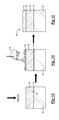
- the magnesium metal M is bonded to the substrate 12 . This may be accomplished, for example, by placing the substrate 12 including the structure 18 grown thereon in a casting die or mold (not shown in the figures), and then over-casting the magnesium metal M onto the substrate surface S, as shown in FIG. 1D .
- Over-casting generally involves introducing (via, e.g., pouring) the metal M (e.g., magnesium), in a molten state, over the aluminum substrate 12 . For instance, solid magnesium is melted into the molten state by heating the magnesium above its melting temperature.
- the molten magnesium metal M reacts with the metal oxide of the structure 18 in the presence of the oxygen to form another, new oxide layer 20 (shown in FIG. 1E ). It is believed that this other oxide layer 20 chemically bonds to the initial oxide layer 18 , where the initial oxide layer 18 chemically bonds to the underlying substrate 12 .
- the oxygen is extracted from the oxygen-containing material introduced onto the surface S and/or into the nano-pores 16 , and is utilized in the reaction at the interfaces between the metal M and the oxide layer 18 (e.g., an interface I 1 at an exposed, top surface of the oxide layer 18 and interface I 2 at the surface of the oxide layer 18 defining each of the nano-pores 16 , as shown in FIG. 1D ) to form the other oxide 20 , shown in FIG. 1E . It is to be understood that a portion of the oxide layer 18 (e.g., the top of the oxide layer 18 , as well as the oxide defining each of the nano-pores 16 ) is consumed during the chemical reaction to form the other oxide 20 .
- Equation (1) An example of a reaction that may take place at the interfaces I 1 , I 2 between the magnesium metal M and the alumina layer 18 is shown by equation (1) below: Mg+Al 2 O 3 +1 ⁇ 2O 2 ⁇ MgAl 2 O 4 (Eqn. 1)
- SnO 2 (if used as the source of oxygen) may be introduced into the nano-pores 16 , and then the molten magnesium metal M may be poured (i.e., over-cast) onto the oxide layer 18 including the nano-pores 16 having the SnO 2 disposed therein.
- the magnesium metal M flows into and fills the nano-pores 16 , and reacts with the oxide layer 18 in the presence of oxygen ions extracted from the SnO 2 .
- the metal portion of the SnO 2 after the oxygen ions have been extracted therefrom, may then go into solution with the molten metal M and either i) become soluble in, or ii) form an intermetallic precipitate in the subsequently solidified, over-cast magnesium metal M.
- the Sn component of the oxide will go into solution with the magnesium metal during over-casting and become dispersed as soluble atoms in its solidified crystal structure.
- the Sn component of the oxide will go into solution with the magnesium metal during over-casting and produce a Sn-containing intermetallic precipitate in the solidified metal. It is believed that the presence of the Sn-containing precipitate does not affect the final structural integrity of the formed part 10 shown in FIG. 1F .
- the reaction for this example i.e., creation of the Sn-containing precipitate
- equation (2) 2Mg+2Al 2 O 3 +SnO 2 ⁇ 2MgAl 2 O 4 +Sn (Eqn. 2)
- the other oxide 20 that is formed is a spinel.
- a spinel is a crystalline material where the oxide anions are arranged in a cubic, close-packed lattice and the cations (i.e., Mg and Al) occupy some or all of the octahedral and tetrahedral sitess in the lattice. It is believed that the formation of the spinel (shown as a layer 20 formed on the oxide layer 18 and inside the nano-pores 16 in FIGS. 1E and 1F ) creates a strong chemical bond between the magnesium M and the aluminum oxide layer 18 . It is further believed that this chemical bond advantageously improves the interfacial strength of the part 10 (shown in FIG. 1F ) formed by the method.
- the over-casting process is typically completed relatively quickly (e.g., within a few milliseconds for a thin-wall casting die).
- the over-casting may be completed before the other oxide- (or spinel-) forming reaction has a chance to complete as well. It may, in some cases, be desirable to apply additional heat to further the oxide- (or spinel-) forming reaction to drive the reaction to completion after the over-casting process is finished. Heating may be accomplished, e.g., by placing the part in an oven, furnace, or the like, or heating may be accomplished via other known heating practices.
- the part 10 is formed upon solidifying the molten metal M so that the solidified metal forms a layer 14 of magnesium (or other metal M) bonded to the substrate 12 ′ (which now includes the substrate metal 12 , the oxide structure 18 , and the spinel 20 ).
- the formation of the oxide structure 18 and the spinel 20 is accomplished during a single application of the magnesium metal M.
- a portion of the magnesium metal Mapplied forms the spinel 20 , at least in part because the amount of metal Mapplied is significantly greater than the amount needed to form the spinel 20 (which depends on the amount (or thickness) of the oxide structure 18 previously formed on the substrate 12 ).
- the alumina Al 2 O 3
- the surface is about 25% porous
- about 30 mg of Al 2 O 3 reacts with about 7 mg of magnesium M to form the spinel 20 .
- Any additional magnesium M becomes the layer 14 .
- the layer 14 of magnesium metal may be formed on the substrate 12 ′ according to the shape of the casting die or mold.
- solidification of the metal M to form the layer 14 includes passively cooling the metal M, which enables the molten metal M that flowed over the oxide structure 18 to produce the spinel layer 20 and the metal layer 14 to cool.
- Passive cooling of the metal may be accomplished, e.g., via heat loss by natural radiation, convection, and/or conduction. In one example, these methods of heat loss may be accomplished by placing the part 10 at room temperature (e.g., at a temperature ranging from about 20° C. to about 30° C.).
- solidification may also be accomplished by placing the part 10 in a cooler or other device to expose the part 10 to colder temperatures that may, in some instances, lessen the amount of time needed to fully solidify the metal.
- the part 10 may be cooled inside the casting die or mold by reducing the temperature of the die or mold.
- the part 10 may be heated to at least 100° C. (or even up to about 300° C.). In this example, the temperature at which the part 10 is heated is still lower than the solidification temperature of the metal, and thus the metal cools as heat is conducted into the substrate 12 and into the die/mold.
- the die/mold may be cooled using oil or water that passes through the die.
- the molten metal M may solidify to form a flat layer 14 (as shown in FIG. 1F , for example), or may take the form of a predefined shape of the casting die or mold used for the over-casting.
- FIGS. 1A through 1D and 1 J Another example of the method will now be described in reference to FIGS. 1A through 1D and 1 J. It is to be understood that this example of the method may also be performed without the step shown at FIG. 1C . The steps of the instant example of the method in conjunction with FIGS. 1A through 1C are the same as described in the example above. Referring back to FIG. 1D , in this example of the method, when the molten magnesium metal M is over-cast onto the structure 18 , the metal M reacts with the metal oxide of the structure 18 and converts essentially the entire oxide structure 18 into a spinel 20 ′.
- the amount of the spinel 20 ′ formed may be controlled by a combination of the starting oxide (i.e., the oxide structure 18 ) thickness, the amount of time that the molten metal M reacts with the starting oxide material 18 , and any subsequent heat treatment applied to the formed part 10 ′ to impart the desired properties to the part 10 ′.
- the entire structure 18 is essentially converted when the spinel 20 ′ forms to a thickness that is greater than about 2 ⁇ m.
- the initial oxide layer 18 is converted into a new oxide which, in this case, is the spinel 20 ′.
- the part 10 ′ formed by this method is schematically shown in FIG. 1J .
- the part 10 ′ formed includes a strong chemical bond formed directly between the substrate 12 and the spinel 20 ′, and between the spinel 20 ′ and the layer 14 of magnesium metal. Further, the metal M, while in the molten state, may flow into the nano-pores 16 of the spinel 20 ′ and chemically bond to the spinel 20 ′ at an exposed, top surface thereof, as well as at the surfaces defining the individual nano-pores 16 .
- the magnesium metal M may partially react with the initial oxide (i.e., the layer 18 ) and convert the partially reacted portion of the initial oxide 18 into a first spinel layer, and further react to create a new oxide (i.e., a second spinel layer) on the first spinel layer. This creates an overall graded spinel.
- FIGS. 1A , 1 B, and 1 D through 1 F Another example of the method will be disclosed hereinbelow in conjunction with FIGS. 1A , 1 B, and 1 D through 1 F.
- This example is essentially the same as the example described above in conjunction with FIGS. 1A through 1F ; however the method does not include the step of providing oxygen ions from another source of oxygen for the reaction. Rather, in this example, upon forming the oxide structure 18 (as shown in FIG. 1B ), the molten metal M is over-cast onto the oxide structure 18 and reacts with oxygen ions, e.g., that are extracted directly from the oxide structure 18 .
- the substrate 12 may include elements that are useful for promoting the oxide reaction.
- the 300 series of aluminum casting alloys contain silicon in its eutectic structure, and the anodization (or other oxide-forming process) described above may be used to oxidize the silicon to form a silica (SiO 2 ) structure 18 .
- the metal M may react with the oxygen of the silica to drive the oxide-forming reaction. Since the magnesium metal tends to react with and reduce the oxide of the structure 18 directly, it is believed that a strong chemical bond may be formed (via, e.g., forming a spinel) between the magnesium metal and the oxide.
- the molten magnesium metal M reacts with oxygen obtained from a gas present in the environment within which the bonding is taking place.
- the gas may include air from the surrounding environment, or the reaction may take place in an oxygen-enriched environment. It is believed that for this example (as well as the example described above where the source of oxygen is introduced directly into the nano-pores 16 ), an interfacial oxide will form at the interfaces I 1 and I 2 , and then the magnesium metal M further reacts with the oxide of the structure 18 to form the spinel.
- the reaction for this example i.e., reacting in an oxygen-enriched environment
- Equation 1 is essentially the same as the reaction shown in Equation 1.
- the oxide layer 18 ′ formed on the substrate surface S is a non-porous layer, as shown in FIG. 1G .
- the substrate 12 is selected from a material that does not form pores when oxidized.
- this material is chromium plated on steel, where the chromium naturally forms an oxide on the surface of the steel.
- the molten metal M is over-cast onto the non-porous layer 18 ′ (as shown in FIG. 1H ) as previously described in conjunction with FIG.
- the metal M reacts with the non-porous oxide layer 18 ′ to form another oxide 20 (e.g., a spinel) (as shown in FIG. 1I ).
- a layer 14 of the magnesium metal M then forms on the other oxide 20 to form the part 10 ′′ (as also shown in FIG. 1I ). It is also contemplated herein to convert essentially the entire oxide structure 18 ′ into the other oxide 20 during over-casting, similar to the example described in conjunction with FIG. 1J above. In other words, the anodized substrate surface S may be completely converted regardless of its porosity.
- the layer 14 of the magnesium metal forms directly on the converted oxide structure.
- any of the example methods described above may be used to form another oxide (e.g., oxide layer 20 . 20 ′) as an intermediate layer between the metal and the substrate (e.g., when the substrate includes the oxide structure formed thereon), or as part of the substrate (e.g., when the oxide structure is entirely converted into the other oxide).
- the combination of materials used to form the part 10 , 10 ′, 10 ′′ needs a favorable free energy to react with the oxide formed on the substrate.
- the structure of the other oxide that forms by the reaction between the over-cast metal and the substrate (or the oxide formed on the substrate) depends, at least in part, on the combination of metals used to form the part 10 , 10 ′, 10 ′′.
- the other oxide that forms is a spinel.
- the spinel is a prototypical spinel having two different cations; Mg +2 and Al +3 .
- a number of binary spinels may form (e.g., normal 2 - 3 , normal 2 - 4 , inverse 2 - 3 , and inverse 2 - 4 ). It may also be possible to create defect spinels such as gamma Al 2 O 3 , which has a single cation and the cation is distributed on both the tetrahedral and octahedral sites of the spinel structure.
- ternary or other higher ordered spinels e.g., a quaternary spinel
- the binary spinels ZnAl 2 O 4 and MgAl 2 O 4 may combine to form a ternary spinel. This may occur, for instance, when one spinel composition forms at an interface inside the nano-pores 16 , and another spinel composition forms on the surface of the oxide layer 18 .
- These spinels may react with each other to form yet another spinel during over-casting or during a subsequent heat treatment process.
- oxides may form an oxide that is not a spinel, and this oxide may take the form of a binary oxide, a ternary oxide, or an oxide having an order higher than ternary.
- the examples of the method have been described above for forming an automotive part. As previously mentioned, the examples of the method may also be used to form non-automotive parts, such as for aircraft, tools, house components (e.g., pipes), and/or the like.
- non-automotive parts such as for aircraft, tools, house components (e.g., pipes), and/or the like.
- the examples of the method have been described above as including forming another oxide as a reaction product from the reaction of the over-cast metal M and the oxide layer 18 , 18 ′. It is to be understood that the examples of the method may also be used for forming other reaction products, such as a nitride, a carbide, a ceramic, or the like. These other products may be formed by the reaction between the over-cast metal M and an appropriate selected material for the layer 18 , 18 ′.
- a thickness ranging from about 0.1 ⁇ m to about 500 ⁇ m should be interpreted to include not only the explicitly recited amount limits of about 0.1 ⁇ m to about 500 ⁇ m, but also to include individual amounts, such as 10 ⁇ m, 50 ⁇ m, 220 ⁇ m, etc., and subranges, such as 50 ⁇ m to 300 ⁇ m, etc.
- individual amounts such as 10 ⁇ m, 50 ⁇ m, 220 ⁇ m, etc.
- subranges such as 50 ⁇ m to 300 ⁇ m, etc.
- when “about” is utilized to describe a value this is meant to encompass minor variations (up to +/ ⁇ 5%) from the stated value.
Abstract
Description
Mg+Al2O3+½O2→MgAl2O4 (Eqn. 1)
2Mg+2Al2O3+SnO2→2MgAl2O4+Sn (Eqn. 2)
Claims (14)
Priority Applications (3)
| Application Number | Priority Date | Filing Date | Title |
|---|---|---|---|
| US13/310,110 US8852359B2 (en) | 2011-05-23 | 2011-12-02 | Method of bonding a metal to a substrate |
| DE102012208333.2A DE102012208333B4 (en) | 2011-05-23 | 2012-05-18 | METHOD FOR CONNECTING A METAL WITH A SUBSTRATE |
| CN201210161519.9A CN102794435B (en) | 2011-05-23 | 2012-05-23 | Method of bonding a metal to a substrate |
Applications Claiming Priority (2)
| Application Number | Priority Date | Filing Date | Title |
|---|---|---|---|
| US201161488995P | 2011-05-23 | 2011-05-23 | |
| US13/310,110 US8852359B2 (en) | 2011-05-23 | 2011-12-02 | Method of bonding a metal to a substrate |
Publications (2)
| Publication Number | Publication Date |
|---|---|
| US20120301734A1 US20120301734A1 (en) | 2012-11-29 |
| US8852359B2 true US8852359B2 (en) | 2014-10-07 |
Family
ID=47140589
Family Applications (1)
| Application Number | Title | Priority Date | Filing Date |
|---|---|---|---|
| US13/310,110 Expired - Fee Related US8852359B2 (en) | 2011-05-23 | 2011-12-02 | Method of bonding a metal to a substrate |
Country Status (3)
| Country | Link |
|---|---|
| US (1) | US8852359B2 (en) |
| CN (1) | CN102794435B (en) |
| DE (1) | DE102012208333B4 (en) |
Cited By (6)
| Publication number | Priority date | Publication date | Assignee | Title |
|---|---|---|---|---|
| US9481034B2 (en) | 2013-03-28 | 2016-11-01 | GM Global Technology Operations LLC | Surface treatment for improved bonding in bi-metallic casting |
| US10086429B2 (en) | 2014-10-24 | 2018-10-02 | GM Global Technology Operations LLC | Chilled-zone microstructures for cast parts made with lightweight metal alloys |
| US10612116B2 (en) | 2016-11-08 | 2020-04-07 | GM Global Technology Operations LLC | Increasing strength of an aluminum alloy |
| US10618107B2 (en) | 2016-04-14 | 2020-04-14 | GM Global Technology Operations LLC | Variable thickness continuous casting for tailor rolling |
| US10927436B2 (en) | 2017-03-09 | 2021-02-23 | GM Global Technology Operations LLC | Aluminum alloys |
| US11767608B2 (en) | 2017-03-06 | 2023-09-26 | Arconic Technologies Llc | Methods of preparing 7xxx aluminum alloys for adhesive bonding, and products relating to the same |
Families Citing this family (14)
| Publication number | Priority date | Publication date | Assignee | Title |
|---|---|---|---|---|
| DE102012011992A1 (en) * | 2012-06-16 | 2013-12-19 | Volkswagen Aktiengesellschaft | Metallic cast component and method of making a metallic cast component |
| US8803328B1 (en) * | 2013-01-22 | 2014-08-12 | International Business Machines Corporation | Random coded integrated circuit structures and methods of making random coded integrated circuit structures |
| TWI588436B (en) * | 2014-05-02 | 2017-06-21 | 遠東科技大學 | Heat transmitting structure as well as manufacturing method and heat dissipation method of the same |
| CN104152915B (en) * | 2014-05-04 | 2017-09-26 | 昆明理工大学 | A kind of preparation method of aluminic acid zinc protective layer |
| US20160376690A1 (en) * | 2015-06-29 | 2016-12-29 | GM Global Technology Operations LLC | Phosphating or anodizing for improved bonding of thermal spray coating on engine cylinder bores |
| CN104999054A (en) * | 2015-08-03 | 2015-10-28 | 东莞劲胜精密组件股份有限公司 | Method for combining different types of aluminum materials and combined part of different types of aluminum materials |
| DE102016120355A1 (en) * | 2016-10-25 | 2018-04-26 | Dr. Ing. H.C. F. Porsche Aktiengesellschaft | Composite component for a motor vehicle |
| JP6869373B2 (en) * | 2017-01-18 | 2021-05-12 | アーコニック テクノロジーズ エルエルシーArconic Technologies Llc | Preparation method of 7XXX aluminum alloy for adhesive bonding and related products |
| CN108237214B (en) * | 2018-01-05 | 2019-11-08 | 天津理工大学 | A kind of preparation method of degradable stratiform Zn-Mg composite material |
| DE102018213490A1 (en) * | 2018-08-10 | 2020-02-13 | Bayerische Motoren Werke Aktiengesellschaft | Component and method for producing a component |
| DE102018007546A1 (en) * | 2018-09-25 | 2020-03-26 | Rheinisch-Westfälische Technische Hochschule (Rwth) Aachen | Process for producing a hybrid component |
| CN111408530B (en) * | 2019-12-25 | 2022-05-10 | 丽水市正阳电力设计院有限公司 | Surface treatment method of weathering resistant steel |
| CN111589892B (en) * | 2020-06-16 | 2021-06-22 | 南京理工大学 | Preparation method of layered aluminum-based composite material plate |
| CN111716084B (en) * | 2020-07-01 | 2021-07-27 | 南京工程学院 | Manufacturing method of copper/steel composite injection mold with honeycomb and embedded nail interface structure |
Citations (14)
| Publication number | Priority date | Publication date | Assignee | Title |
|---|---|---|---|---|
| US4127451A (en) | 1976-02-26 | 1978-11-28 | The Boeing Company | Method for providing environmentally stable aluminum surfaces for adhesive bonding and product produced |
| US5131987A (en) | 1989-12-26 | 1992-07-21 | Aluminum Company Of America | Process for making an adhesively bonded aluminum article |
| US5486283A (en) | 1993-08-02 | 1996-01-23 | Rohr, Inc. | Method for anodizing aluminum and product produced |
| US5543130A (en) * | 1992-01-24 | 1996-08-06 | Ngk Insulators, Ltd. | Metal ceramic composite structure |
| US5774336A (en) | 1996-02-20 | 1998-06-30 | Heat Technology, Inc. | High-terminal conductivity circuit board |
| DE19937934A1 (en) | 1999-08-11 | 2001-02-15 | Bayerische Motoren Werke Ag | Cylinder crankcase, method for manufacturing the cylinder liners therefor and method for manufacturing the cylinder crankcase with these cylinder liners |
| US6450396B1 (en) | 2001-07-02 | 2002-09-17 | General Motors Corporation | Method for making weldless magnesium/aluminum bonded components |
| US6531013B2 (en) | 2001-05-15 | 2003-03-11 | Alcoa Inc. | Adhesive bonding process for aluminum alloy bodies including hypophosphorous acid anodizing |
| US6852266B2 (en) | 2001-01-19 | 2005-02-08 | Korry Electronics Co. | Ultrasonic assisted deposition of anti-stick films on metal oxides |
| US6887321B2 (en) | 2002-05-22 | 2005-05-03 | United Technologies Corporation | Corrosion resistant surface treatment for structural adhesive bonding to metal |
| DE102007059771A1 (en) | 2007-12-12 | 2009-06-18 | Daimler Ag | Cylinder bush or cylinder liner made of gray iron- or aluminum alloy for casting in a light metal alloy on the basis of aluminum or aluminum/magnesium, comprises a conditioning coating for casting |
| DE102010018004A1 (en) | 2009-04-28 | 2010-12-09 | GM Global Technology Operations, Inc., Detroit | A method of forming a coated article comprising a magnesium alloy |
| DE102011115321A1 (en) | 2010-10-12 | 2012-04-12 | Gm Global Technology Operations Llc (N.D.Ges.D. Staates Delaware) | Bimetallgussteil |
| US8216712B1 (en) * | 2008-01-11 | 2012-07-10 | Enovix Corporation | Anodized metallic battery separator having through-pores |
Family Cites Families (7)
| Publication number | Priority date | Publication date | Assignee | Title |
|---|---|---|---|---|
| JPS532103A (en) * | 1976-06-27 | 1978-01-10 | Miyako Tachihara | Printing plate material |
| DK193287A (en) * | 1986-04-16 | 1987-10-17 | Alcan Int Ltd | COMPOSITE MEMBRANE |
| KR960031023A (en) * | 1995-02-22 | 1996-09-17 | 와다 요시히로 | METHOD FOR MANUFACTURING PARTIAL COMPOSITE REINFORCED LIGHT-ALLOY PARTS AND PRE-MOLDED FABRICATED THEREFOR |
| US20040035547A1 (en) * | 2002-08-20 | 2004-02-26 | 3M Innovative Properties Company | Metal matrix composites, and methods for making the same |
| US7435376B2 (en) * | 2002-12-20 | 2008-10-14 | Ceramtec Ag | Composites and method for manufacturing same |
| US20070116972A1 (en) * | 2005-11-21 | 2007-05-24 | United Technologies Corporation | Barrier coating system for refractory metal core |
| US9028959B2 (en) * | 2008-10-03 | 2015-05-12 | Sumitomo Electric Industries, Ltd. | Composite member |
-
2011
- 2011-12-02 US US13/310,110 patent/US8852359B2/en not_active Expired - Fee Related
-
2012
- 2012-05-18 DE DE102012208333.2A patent/DE102012208333B4/en not_active Expired - Fee Related
- 2012-05-23 CN CN201210161519.9A patent/CN102794435B/en not_active Expired - Fee Related
Patent Citations (15)
| Publication number | Priority date | Publication date | Assignee | Title |
|---|---|---|---|---|
| US4127451A (en) | 1976-02-26 | 1978-11-28 | The Boeing Company | Method for providing environmentally stable aluminum surfaces for adhesive bonding and product produced |
| US5131987A (en) | 1989-12-26 | 1992-07-21 | Aluminum Company Of America | Process for making an adhesively bonded aluminum article |
| US5324587A (en) | 1989-12-26 | 1994-06-28 | Aluminum Company Of America | Adhesively bonded aluminum |
| US5543130A (en) * | 1992-01-24 | 1996-08-06 | Ngk Insulators, Ltd. | Metal ceramic composite structure |
| US5486283A (en) | 1993-08-02 | 1996-01-23 | Rohr, Inc. | Method for anodizing aluminum and product produced |
| US5774336A (en) | 1996-02-20 | 1998-06-30 | Heat Technology, Inc. | High-terminal conductivity circuit board |
| DE19937934A1 (en) | 1999-08-11 | 2001-02-15 | Bayerische Motoren Werke Ag | Cylinder crankcase, method for manufacturing the cylinder liners therefor and method for manufacturing the cylinder crankcase with these cylinder liners |
| US6852266B2 (en) | 2001-01-19 | 2005-02-08 | Korry Electronics Co. | Ultrasonic assisted deposition of anti-stick films on metal oxides |
| US6531013B2 (en) | 2001-05-15 | 2003-03-11 | Alcoa Inc. | Adhesive bonding process for aluminum alloy bodies including hypophosphorous acid anodizing |
| US6450396B1 (en) | 2001-07-02 | 2002-09-17 | General Motors Corporation | Method for making weldless magnesium/aluminum bonded components |
| US6887321B2 (en) | 2002-05-22 | 2005-05-03 | United Technologies Corporation | Corrosion resistant surface treatment for structural adhesive bonding to metal |
| DE102007059771A1 (en) | 2007-12-12 | 2009-06-18 | Daimler Ag | Cylinder bush or cylinder liner made of gray iron- or aluminum alloy for casting in a light metal alloy on the basis of aluminum or aluminum/magnesium, comprises a conditioning coating for casting |
| US8216712B1 (en) * | 2008-01-11 | 2012-07-10 | Enovix Corporation | Anodized metallic battery separator having through-pores |
| DE102010018004A1 (en) | 2009-04-28 | 2010-12-09 | GM Global Technology Operations, Inc., Detroit | A method of forming a coated article comprising a magnesium alloy |
| DE102011115321A1 (en) | 2010-10-12 | 2012-04-12 | Gm Global Technology Operations Llc (N.D.Ges.D. Staates Delaware) | Bimetallgussteil |
Cited By (6)
| Publication number | Priority date | Publication date | Assignee | Title |
|---|---|---|---|---|
| US9481034B2 (en) | 2013-03-28 | 2016-11-01 | GM Global Technology Operations LLC | Surface treatment for improved bonding in bi-metallic casting |
| US10086429B2 (en) | 2014-10-24 | 2018-10-02 | GM Global Technology Operations LLC | Chilled-zone microstructures for cast parts made with lightweight metal alloys |
| US10618107B2 (en) | 2016-04-14 | 2020-04-14 | GM Global Technology Operations LLC | Variable thickness continuous casting for tailor rolling |
| US10612116B2 (en) | 2016-11-08 | 2020-04-07 | GM Global Technology Operations LLC | Increasing strength of an aluminum alloy |
| US11767608B2 (en) | 2017-03-06 | 2023-09-26 | Arconic Technologies Llc | Methods of preparing 7xxx aluminum alloys for adhesive bonding, and products relating to the same |
| US10927436B2 (en) | 2017-03-09 | 2021-02-23 | GM Global Technology Operations LLC | Aluminum alloys |
Also Published As
| Publication number | Publication date |
|---|---|
| DE102012208333A1 (en) | 2012-11-29 |
| DE102012208333B4 (en) | 2014-12-04 |
| CN102794435A (en) | 2012-11-28 |
| US20120301734A1 (en) | 2012-11-29 |
| CN102794435B (en) | 2014-11-26 |
Similar Documents
| Publication | Publication Date | Title |
|---|---|---|
| US8852359B2 (en) | Method of bonding a metal to a substrate | |
| US8889226B2 (en) | Method of bonding a metal to a substrate | |
| US8992696B2 (en) | Method of bonding a metal to a substrate | |
| US20220088674A1 (en) | Castings and Manufacture Methods | |
| Chen et al. | Fabrication and characterization of highly-ordered valve-metal oxide nanotubes and their derivative nanostructures | |
| JP2006520697A (en) | Process for making nanostructured components | |
| JP2011513974A (en) | Process for the production of unsupported articles of pure or doped semiconductor material | |
| EP3421646A1 (en) | Colouring method of aluminium alloy member | |
| Zhou et al. | Electroless Ni–P alloys on nanoporous ATO surface of Ti substrate | |
| JP2016183390A (en) | Metallic porous body | |
| CN109694965A (en) | A kind of copper-based surfaces porous structure and its manufacturing method | |
| Zhao et al. | Directional hierarchical porous Cu prepared by one-step etching 3D printed Fe-Cu alloy with two-stage phase separation structure | |
| CN111254308A (en) | Method for improving high-temperature stability of metal twin crystal | |
| US6287446B1 (en) | High porosity three-dimensional structures in chromium based alloys | |
| JP2020033591A (en) | Production method of metal compact having anodic oxide film, metal compact having anodic oxide film, piston, and internal combustion engine | |
| CN1432669A (en) | Micro arc process to produce ceramic layer on surface of zinc oxide and aluminium alloy | |
| JP4392087B2 (en) | Surface treatment method of die casting mold and die | |
| KR101266302B1 (en) | Method for forming ceramic coating layer on aluminum substrate | |
| US20140216942A1 (en) | Carbon-Metal Thermal Management Substrates | |
| CN114717626B (en) | Method for prolonging service life of high-temperature alloy through prefabricated oxide film | |
| KR102289658B1 (en) | Mold for continuous casting and coating method of mold for continuous casting | |
| JP5931516B2 (en) | Method for manufacturing molten aluminum contact member | |
| CN115679416A (en) | Compact micro-arc oxidation ceramic film layer with self-sealing hole on magnesium alloy surface, preparation method and application | |
| CN109208045A (en) | The processing technology and fuel rod clad of fuel rod clad | |
| TW200302160A (en) | Composite metal material and production method therefor, etched metal material and production method therefor, and electrolytic capacitor |
Legal Events
| Date | Code | Title | Description |
|---|---|---|---|
| AS | Assignment |
Owner name: GM GLOBAL TECHNOLOGY OPERATIONS LLC, MICHIGAN Free format text: ASSIGNMENT OF ASSIGNORS INTEREST;ASSIGNORS:WALKER, MICHAEL J.;POWELL, BOB R., JR.;LUO, AIHUA A.;AND OTHERS;SIGNING DATES FROM 20111123 TO 20111129;REEL/FRAME:027355/0875 |
|
| AS | Assignment |
Owner name: WILMINGTON TRUST COMPANY, DELAWARE Free format text: SECURITY AGREEMENT;ASSIGNOR:GM GLOBAL TECHNOLOGY OPERATIONS LLC;REEL/FRAME:028458/0184 Effective date: 20101027 |
|
| FEPP | Fee payment procedure |
Free format text: PAYOR NUMBER ASSIGNED (ORIGINAL EVENT CODE: ASPN); ENTITY STATUS OF PATENT OWNER: LARGE ENTITY |
|
| STCF | Information on status: patent grant |
Free format text: PATENTED CASE |
|
| AS | Assignment |
Owner name: GM GLOBAL TECHNOLOGY OPERATIONS LLC, MICHIGAN Free format text: RELEASE BY SECURED PARTY;ASSIGNOR:WILMINGTON TRUST COMPANY;REEL/FRAME:034186/0776 Effective date: 20141017 |
|
| MAFP | Maintenance fee payment |
Free format text: PAYMENT OF MAINTENANCE FEE, 4TH YEAR, LARGE ENTITY (ORIGINAL EVENT CODE: M1551) Year of fee payment: 4 |
|
| FEPP | Fee payment procedure |
Free format text: MAINTENANCE FEE REMINDER MAILED (ORIGINAL EVENT CODE: REM.); ENTITY STATUS OF PATENT OWNER: LARGE ENTITY |
|
| LAPS | Lapse for failure to pay maintenance fees |
Free format text: PATENT EXPIRED FOR FAILURE TO PAY MAINTENANCE FEES (ORIGINAL EVENT CODE: EXP.); ENTITY STATUS OF PATENT OWNER: LARGE ENTITY |
|
| STCH | Information on status: patent discontinuation |
Free format text: PATENT EXPIRED DUE TO NONPAYMENT OF MAINTENANCE FEES UNDER 37 CFR 1.362 |
|
| FP | Lapsed due to failure to pay maintenance fee |
Effective date: 20221007 |