US8851459B2 - Elastic device structure - Google Patents
Elastic device structure Download PDFInfo
- Publication number
- US8851459B2 US8851459B2 US13/559,782 US201213559782A US8851459B2 US 8851459 B2 US8851459 B2 US 8851459B2 US 201213559782 A US201213559782 A US 201213559782A US 8851459 B2 US8851459 B2 US 8851459B2
- Authority
- US
- United States
- Prior art keywords
- connection
- disposed
- section
- device structure
- elastic device
- Prior art date
- Legal status (The legal status is an assumption and is not a legal conclusion. Google has not performed a legal analysis and makes no representation as to the accuracy of the status listed.)
- Active, expires
Links
Images


Classifications
-
- F—MECHANICAL ENGINEERING; LIGHTING; HEATING; WEAPONS; BLASTING
- F16—ENGINEERING ELEMENTS AND UNITS; GENERAL MEASURES FOR PRODUCING AND MAINTAINING EFFECTIVE FUNCTIONING OF MACHINES OR INSTALLATIONS; THERMAL INSULATION IN GENERAL
- F16F—SPRINGS; SHOCK-ABSORBERS; MEANS FOR DAMPING VIBRATION
- F16F1/00—Springs
- F16F1/02—Springs made of steel or other material having low internal friction; Wound, torsion, leaf, cup, ring or the like springs, the material of the spring not being relevant
- F16F1/04—Wound springs
- F16F1/12—Attachments or mountings
- F16F1/128—Attachments or mountings with motion-limiting means, e.g. with a full-length guide element or ball joint connections; with protective outer cover
-
- F—MECHANICAL ENGINEERING; LIGHTING; HEATING; WEAPONS; BLASTING
- F16—ENGINEERING ELEMENTS AND UNITS; GENERAL MEASURES FOR PRODUCING AND MAINTAINING EFFECTIVE FUNCTIONING OF MACHINES OR INSTALLATIONS; THERMAL INSULATION IN GENERAL
- F16F—SPRINGS; SHOCK-ABSORBERS; MEANS FOR DAMPING VIBRATION
- F16F3/00—Spring units consisting of several springs, e.g. for obtaining a desired spring characteristic
- F16F3/02—Spring units consisting of several springs, e.g. for obtaining a desired spring characteristic with springs made of steel or of other material having low internal friction
- F16F3/04—Spring units consisting of several springs, e.g. for obtaining a desired spring characteristic with springs made of steel or of other material having low internal friction composed only of wound springs
Definitions
- the present invention relates generally to an improved elastic device structure, and more particularly to an elastic device structure, which has simplified components and is convenient to install and uninstall. Moreover, the elastic device structure can be repeatedly used.
- FIGS. 1 and 2 show a conventional elastic device applied to two slide members, which are slidable relative to each other.
- the elastic device includes a first connection seat 6 , a second connection seat 7 and multiple elastic members 3 .
- the first connection seat 6 is formed with a pivot hole 61 for pivotally connecting with a slide member and a connection passageway 62 .
- a bearing 611 is disposed in the pivot hole 61 as necessary.
- At least one slide guide slot 621 with two closed ends is disposed on a wall of the connection passage 62 .
- multiple receiving sockets 63 are disposed on two sides of the connection passageway 62 .
- a passage 631 passing through the first connection seat 6 is formed in each receiving socket 63 .
- the second connection seat 7 is formed with a pivot hole 71 for pivotally connecting with a relative slide member and a connection protrusion 72 .
- a bearing 711 is disposed in the pivot hole 71 as necessary.
- At least one slide guide raised block 721 is disposed on the connection protrusion 72 .
- the slide guide raised block 721 is inlaid in the slide guide slot 621 .
- Multiple receiving sockets 73 are disposed on two sides of the connection protrusion 72 .
- a passage 731 passing through the second connection seat 7 is formed in each receiving socket 73 .
- Each elastic member 3 is fitted around a guide rod 31 .
- the slide guide raised block 721 is restricted to slide within the slide guide slot 621 .
- the conventional elastic device has some shortcomings as follows:
- connection seats are slidably connected to each other and the elastic members are disposed between the connection seats. Accordingly, the connection seats can be elastically slid toward each other or away from each other.
- the components of the elastic device are simplified so that the development and manufacturing cost is lowered to increase economic efficiency.
- the elastic device structure of the present invention includes: two connection seats oppositely connected with each other, each connection seat being defined with a central line and having a protruding connection section and a connected section, the connection section and the connected section being symmetrically disposed on two sides of the central line, a lateral hook being disposed on the connection section, the connected section being formed with a receiving channel for receiving the connection section of the other connection seat, a stop raised block being disposed on the receiving channel and positioned at a dead end of slide paths of the lateral hook of the other connection seat; and at least one elastic member connected and disposed between the two connection seats.
- At least one receiving socket is disposed on each connection seat.
- the receiving sockets of the two connection seats are opposite to each other.
- Two end sections of the elastic member respectively extend into the receiving sockets of the connection seats and are located therein.
- connection seat a passage passing through the connection seat is formed in each receiving socket for receiving a guide rod.
- the elastic member is fitted on the guide rod.
- a lateral protruding edge is disposed on one side of the connection section, which side is distal from the lateral hook.
- a stop wall is disposed on the receiving channel of the connected section corresponding to the lateral protruding edge. The stop wall serves to press the lateral protruding edge of the other connection seat.
- the lateral hook is disposed at one end of the connection section, which end is distal from the connection seat and the stop raised block is disposed at one end of the connected section, which end is distal from the connection seat.
- a slide guide slope is formed on one end of the lateral protruding edge, which end is distal from the connection seat.
- each connection seat is formed with a connection notch with a larger interior and a smaller opening.
- connection notch a circumference of the connection notch is formed with at least one elastic split.
- FIG. 1 is a perspective exploded view of a conventional elastic device applied between two slide members
- FIG. 2 is a perspective assembled view of the conventional elastic device applied between two slide members
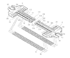
- FIG. 3 is a perspective exploded view of the present invention
- FIG. 4 is a perspective assembled view of the two connection seats of the present invention.
- FIG. 5 is an enlarged view of circled area A of FIG. 4 ;
- FIG. 6 is a perspective assembled view of the present invention.
- FIG. 7 is a plane view showing the operation of the present invention connected between two slide member.
- FIG. 8 is another plane view showing the operation of the present invention connected between two slide members.
- the elastic device structure of the present invention includes two identical connection seats 1 , 2 and multiple elastic members 3 .
- Each of the connection seats 1 , 2 is formed with a connection notch 14 , 24 with a larger interior and a smaller opening.
- An inner circumference of the connection notch 14 , 24 is formed with at least one recessed elastic split 141 , 241 .
- a central line CL is defined at the middle of the connection notch 14 , 24 between opposite sides thereof.
- a connection section 11 , 21 and a connected section 12 , 22 are symmetrically disposed on two sides of the central line CL.
- Multiple recessed receiving sockets 13 , 23 are disposed on two sides of the connection section 11 , 21 and the connected section 12 , 22 and arranged in a direction away from the central line CL.
- a lateral protruding edge 111 , 211 is disposed on one side of the connection section 11 , 21 , which side is proximal to the central line CL.
- An outer end section of the lateral protruding edge 111 , 211 , (which end section is distal from the connection seat 1 , 2 ) is formed with a slide guide slope 112 , 212 .
- connection section 11 , 21 One side of the outer end section of the connection section 11 , 21 , (which side is distal from the central line CL) is formed with a lateral hook 113 , 213 laterally protruding from the outer end section of the connection section 11 , 21 .
- the connected section 12 , 22 is formed with a receiving channel 121 , 221 for receiving the other connection section 11 , 21 .
- One side of the receiving channel 121 , 221 which side is proximal to the central line CL is formed with a stop wall 123 , 223 for partially concealing the receiving channel 121 , 221 .
- a stop raised block 122 , 222 is disposed on one side of the outer end section (distal from the connection seat 1 , 2 ) of the receiving channel 121 , 221 , which side is distal from the central line CL.
- a passage 131 , 231 passing through the connection seat 1 , 2 is formed in each receiving socket 13 , 23 .
- the elastic member 3 can be a spring.
- a guide rod 31 is fitted in and through the elastic member 3 .
- connection sections 11 , 21 of the two connection seats 1 , 2 are oppositely extended into the receiving channels 221 , 121 of the connected sections 22 , 12 of the other connection seats 2 , 1 .
- the slide guide slopes 112 , 212 narrow the cross sections of the end sections of the connection sections 11 , 21 to be smaller than the width of the receiving channels 221 , 121 . Accordingly, when the lateral hooks 113 , 213 pass through the stop raised blocks 222 , 122 , the lateral hooks 113 , 213 will be transversely biased away from the stop raised blocks 222 , 122 within the receiving channels 221 , 121 . Accordingly, the insertion is facilitated.
- connection sections 11 , 21 are securely inlaid in the receiving channels 121 , 221 of the connected sections 12 , 22 and smoothly relatively slidable within the receiving channels 121 , 221 without loosening.
- the stop raised blocks 122 , 222 are positioned at the dead ends of the slide paths of the lateral hooks 213 , 113 to stop the lateral hooks 213 , 113 , whereby the connection sections 11 , 21 are prevented from detaching from the connected sections 12 , 22 .
- Two end sections of the elastic members 3 respectively abut against bottom walls of the receiving sockets 131 , 231 of the connection seats 1 , 2 .
- Two end sections of the guide rods 31 are respectively extended into the passages 131 , 231 and located.
- the elastic device 3 composed of the connection seats 1 , 2 and the multiple elastic members 3 is mounted on a slide member 4 and a relative slide member 5 , which are slidable relative to each other.
- Two pivot pins 41 , 51 are previously respectively disposed on the slide member 4 and the relative slide member 5 .
- the connection seats 1 , 2 are forced toward each other to compress the elastic members 3 .
- the connection notches 14 , 24 of the connection seats 1 , 2 are fitted on the pivot pins 41 , 51 .
- the elastic splits 141 , 241 permit the connection notches 14 , 24 to elastically expand to facilitate fitting of the pivot pins 41 , 51 ).
- the slide member 4 and the relative slide member 5 can be elastically connected with the elastic members 3 via the connection seats 1 , 2 .
- the elastic device structure has simplified components and can be easily installed and uninstalled. Moreover, the cost for the elastic device structure is lower.
Landscapes
- Engineering & Computer Science (AREA)
- General Engineering & Computer Science (AREA)
- Mechanical Engineering (AREA)
- Mutual Connection Of Rods And Tubes (AREA)
- Pivots And Pivotal Connections (AREA)
- Seats For Vehicles (AREA)
Abstract
Description
-
- 1. The slide guide raised
block 721 of theconnection protrusion 72 must first pass through the opening of theconnection passageway 62 before going into theslide guide slot 621. However, the size of the opening of theconnection passageway 62 is adapted to theconnection protrusion 72. As a result, it is inconvenient for theconnection protrusion 72 with the slide guide raisedblock 721 to extend into theconnection passageway 62. - 2. The opening of the
connection passageway 62 must be properly larger than theconnection protrusion 72 to allow theconnection protrusion 72 with the slide guide raisedblock 721 to pass through the opening. Therefore, after the slide guide raisedblock 721 is inlaid in theslide guide slot 621, a gap is formed between theconnection protrusion 72 and theconnection passageway 62. As a result, theconnection protrusion 72 is likely to shake and loosen from theconnection passageway 62. This will affect the assembling quality. - 3. The first and
second connection seats close pivot holes second connection seats
- 1. The slide guide raised
Claims (12)
Applications Claiming Priority (3)
| Application Number | Priority Date | Filing Date | Title |
|---|---|---|---|
| TW101208132A | 2012-04-30 | ||
| TW101208132U TWM441997U (en) | 2012-04-30 | 2012-04-30 | Improved structure of elastic device |
| TW101208132 | 2012-04-30 |
Publications (2)
| Publication Number | Publication Date |
|---|---|
| US20130285297A1 US20130285297A1 (en) | 2013-10-31 |
| US8851459B2 true US8851459B2 (en) | 2014-10-07 |
Family
ID=47718330
Family Applications (1)
| Application Number | Title | Priority Date | Filing Date |
|---|---|---|---|
| US13/559,782 Active 2032-12-13 US8851459B2 (en) | 2012-04-30 | 2012-07-27 | Elastic device structure |
Country Status (2)
| Country | Link |
|---|---|
| US (1) | US8851459B2 (en) |
| TW (1) | TWM441997U (en) |
Cited By (1)
| Publication number | Priority date | Publication date | Assignee | Title |
|---|---|---|---|---|
| US20160040739A1 (en) * | 2014-08-09 | 2016-02-11 | Structural Fuse, LLC | Sacrificial energy dissipation mechanism |
Citations (7)
| Publication number | Priority date | Publication date | Assignee | Title |
|---|---|---|---|---|
| US2405644A (en) * | 1943-12-02 | 1946-08-13 | Miner Inc W H | Friction shock absorber |
| US2581531A (en) * | 1948-07-13 | 1952-01-08 | Miner Inc W H | Friction shock absorbing mechanism for railway car trucks |
| US2581543A (en) * | 1948-06-25 | 1952-01-08 | Miner Inc W H | Friction shock absorber for railway car trucks |
| US20080254844A1 (en) * | 2005-09-29 | 2008-10-16 | Hitech Parts Co., Ltd. | Link assembly with springs which can be extended and contracted and slider assembly for sliding type mobile phone having the link assembly |
| US20100016043A1 (en) * | 2008-07-18 | 2010-01-21 | Casio Hitachi Mobile Communications Co., Ltd. | Slide Mechanism and Electronic Apparatus |
| US20100154168A1 (en) * | 2006-05-24 | 2010-06-24 | Diabell Co., Ltd. | Hinge device for cellular phone |
| US7831285B2 (en) * | 2004-03-08 | 2010-11-09 | Hitech Parts Co., Ltd. | Slider assembly for sliding-type mobile phone and cellular phone having the slider assembly |
-
2012
- 2012-04-30 TW TW101208132U patent/TWM441997U/en not_active IP Right Cessation
- 2012-07-27 US US13/559,782 patent/US8851459B2/en active Active
Patent Citations (8)
| Publication number | Priority date | Publication date | Assignee | Title |
|---|---|---|---|---|
| US2405644A (en) * | 1943-12-02 | 1946-08-13 | Miner Inc W H | Friction shock absorber |
| US2581543A (en) * | 1948-06-25 | 1952-01-08 | Miner Inc W H | Friction shock absorber for railway car trucks |
| US2581531A (en) * | 1948-07-13 | 1952-01-08 | Miner Inc W H | Friction shock absorbing mechanism for railway car trucks |
| US7831285B2 (en) * | 2004-03-08 | 2010-11-09 | Hitech Parts Co., Ltd. | Slider assembly for sliding-type mobile phone and cellular phone having the slider assembly |
| US20080254844A1 (en) * | 2005-09-29 | 2008-10-16 | Hitech Parts Co., Ltd. | Link assembly with springs which can be extended and contracted and slider assembly for sliding type mobile phone having the link assembly |
| US20100154168A1 (en) * | 2006-05-24 | 2010-06-24 | Diabell Co., Ltd. | Hinge device for cellular phone |
| US8265720B2 (en) * | 2006-05-24 | 2012-09-11 | Diabell Co., Ltd. | Sliding device for cellular phone |
| US20100016043A1 (en) * | 2008-07-18 | 2010-01-21 | Casio Hitachi Mobile Communications Co., Ltd. | Slide Mechanism and Electronic Apparatus |
Cited By (2)
| Publication number | Priority date | Publication date | Assignee | Title |
|---|---|---|---|---|
| US20160040739A1 (en) * | 2014-08-09 | 2016-02-11 | Structural Fuse, LLC | Sacrificial energy dissipation mechanism |
| US10253837B2 (en) * | 2014-08-09 | 2019-04-09 | Structural Fuse, LLC | Sacrificial energy dissipation mechanism |
Also Published As
| Publication number | Publication date |
|---|---|
| US20130285297A1 (en) | 2013-10-31 |
| TWM441997U (en) | 2012-11-21 |
Similar Documents
| Publication | Publication Date | Title |
|---|---|---|
| US9230606B2 (en) | Mounting apparatus assembly | |
| US8848379B2 (en) | Mounting apparatus for memory card | |
| US8246373B2 (en) | Mounting apparatus for expansion card | |
| TW201324974A (en) | Expansion card socket and motherboard having the expansion card socket | |
| US9520035B2 (en) | Point of sale device | |
| US8517756B2 (en) | Electrical connector assembly | |
| US9980401B1 (en) | Locking apparatus and electronic device having same | |
| US20150009619A1 (en) | Fastening device for data storage device | |
| US20160299534A1 (en) | Electronic device | |
| US9225110B2 (en) | Fastening device of plug-socket combination | |
| US8500485B2 (en) | Fixing apparatus for connector | |
| US8851459B2 (en) | Elastic device structure | |
| US20140250960A1 (en) | Rekeyable lock | |
| KR20160123865A (en) | Spacer for connector and connector including the same | |
| US20160198807A1 (en) | Belt buckle | |
| US8797751B2 (en) | Power distribution unit and server cabinet with the power distribution unit | |
| US20140375185A1 (en) | Electronic device enclosure with cover | |
| EP2219349A3 (en) | Case assembly for electronic appliance | |
| US9635777B2 (en) | Electronic device | |
| US20140146502A1 (en) | Circuit board mounting apparatus | |
| US8052460B1 (en) | Electrical connector assembly and adjustable receiving connector thereof | |
| US20130149138A1 (en) | Fastening apparatus for fan | |
| US8221141B2 (en) | Electrical connector | |
| US20050032405A1 (en) | Power cable plug assembly having replaceable plug | |
| CN207602871U (en) | A kind of heavy duty module frame structure |
Legal Events
| Date | Code | Title | Description |
|---|---|---|---|
| AS | Assignment |
Owner name: FIRST DOME CORPORATION, TAIWAN Free format text: ASSIGNMENT OF ASSIGNORS INTEREST;ASSIGNORS:HSU, AN SZU;KUO, YUNG SHENG;WU, SANDY;REEL/FRAME:028663/0021 Effective date: 20120502 |
|
| AS | Assignment |
Owner name: FIRST DOME CORPORATION, TAIWAN Free format text: CORRECTIVE ASSIGNMENT TO CORRECT THE THIRD ASSIGNOR'S ADDRESS PREVIOUSLY RECORDED ON REEL 28663, FRAME 21;ASSIGNORS:HSU, AN SZU;KUO, YUNG SHENG;WU, SANDY;REEL/FRAME:028816/0713 Effective date: 20120502 |
|
| STCF | Information on status: patent grant |
Free format text: PATENTED CASE |
|
| MAFP | Maintenance fee payment |
Free format text: PAYMENT OF MAINTENANCE FEE, 4TH YEAR, LARGE ENTITY (ORIGINAL EVENT CODE: M1551) Year of fee payment: 4 |
|
| MAFP | Maintenance fee payment |
Free format text: PAYMENT OF MAINTENANCE FEE, 8TH YEAR, LARGE ENTITY (ORIGINAL EVENT CODE: M1552); ENTITY STATUS OF PATENT OWNER: LARGE ENTITY Year of fee payment: 8 |
|
| MAFP | Maintenance fee payment |
Free format text: PAYMENT OF MAINTENANCE FEE, 12TH YEAR, LARGE ENTITY (ORIGINAL EVENT CODE: M1553); ENTITY STATUS OF PATENT OWNER: LARGE ENTITY Year of fee payment: 12 |