US8851057B2 - Bow press - Google Patents
Bow press Download PDFInfo
- Publication number
- US8851057B2 US8851057B2 US13/345,168 US201213345168A US8851057B2 US 8851057 B2 US8851057 B2 US 8851057B2 US 201213345168 A US201213345168 A US 201213345168A US 8851057 B2 US8851057 B2 US 8851057B2
- Authority
- US
- United States
- Prior art keywords
- bow
- support members
- links
- brackets
- linkage
- Prior art date
- Legal status (The legal status is an assumption and is not a legal conclusion. Google has not performed a legal analysis and makes no representation as to the accuracy of the status listed.)
- Active, expires
Links
- 230000007246 mechanism Effects 0.000 claims abstract description 87
- 230000004044 response Effects 0.000 claims abstract description 7
- 230000007935 neutral effect Effects 0.000 claims description 6
- 238000000926 separation method Methods 0.000 claims description 4
- 150000001875 compounds Chemical class 0.000 description 14
- 238000000034 method Methods 0.000 description 9
- 238000005452 bending Methods 0.000 description 7
- 230000000712 assembly Effects 0.000 description 4
- 238000000429 assembly Methods 0.000 description 4
- 230000006378 damage Effects 0.000 description 4
- 230000008439 repair process Effects 0.000 description 4
- 239000012141 concentrate Substances 0.000 description 3
- 230000008878 coupling Effects 0.000 description 3
- 238000010168 coupling process Methods 0.000 description 3
- 238000005859 coupling reaction Methods 0.000 description 3
- 239000000463 material Substances 0.000 description 3
- 230000008901 benefit Effects 0.000 description 2
- 208000027418 Wounds and injury Diseases 0.000 description 1
- 230000009471 action Effects 0.000 description 1
- 230000008859 change Effects 0.000 description 1
- 239000002131 composite material Substances 0.000 description 1
- 230000007423 decrease Effects 0.000 description 1
- 238000006073 displacement reaction Methods 0.000 description 1
- 208000014674 injury Diseases 0.000 description 1
- 238000012423 maintenance Methods 0.000 description 1
- 230000000737 periodic effect Effects 0.000 description 1
- 230000035945 sensitivity Effects 0.000 description 1
- 239000000126 substance Substances 0.000 description 1
- 230000007704 transition Effects 0.000 description 1
Images


Classifications
-
- F—MECHANICAL ENGINEERING; LIGHTING; HEATING; WEAPONS; BLASTING
- F41—WEAPONS
- F41B—WEAPONS FOR PROJECTING MISSILES WITHOUT USE OF EXPLOSIVE OR COMBUSTIBLE PROPELLANT CHARGE; WEAPONS NOT OTHERWISE PROVIDED FOR
- F41B5/00—Bows; Crossbows
- F41B5/14—Details of bows; Accessories for arc shooting
- F41B5/1442—Accessories for arc or bow shooting
- F41B5/1449—Bow tensioning devices; Bow presses; Rigs for bow assembly or maintenance
-
- F14B5/1449—
Definitions
- This disclosure relates to a bow press are used for installing, replacing, or adjustment of a bow string or components of bows.
- Compound bows are widely used by archers.
- the popularity of the compound bow is mainly due to the advantage provided in the reduced pull force required at full draw together with the resulting increase in accuracy.
- the pull on the bow string is high at the beginning of the draw where the archer at this point is able to exert maximum force.
- eccentrically mounted pulleys or cams of the compound bow which decreases the draw force needed to maintain the bow string in the drawn position, while maximizing the energy stored in the limbs of the bow.
- it is relatively easy to hold the arrow and bow string and much easier to perfect aiming technique and proper release resulting in increased accuracy.
- a typical compound bow includes one or more eccentrically mounted pulleys or cams pivotably attached relative the bow limbs and serves to support and control the movement of a bow string.
- Stringing or tuning of compound bows is critical to achieve a proper balance or synchronization of the eccentrically mounted pulleys or cams.
- the complexity of the stringing and the sensitivity to proper tuning of the bow makes it undesirable to unstring the bow when it is not in use. In some cases it is impossible to string and tune such a bow without the aid of an apparatus commonly known as a bow press.
- FIG. 1 illustrates the prior art bow press 200 disclosed in U.S. Pat. No. 5,370,103 (Desselle). Outside surfaces of the limbs 202 of the bow 204 are positioned on outer supports 206 . Inner members 208 are engaged with inside surface of riser 210 . Drive system 212 moves member 214 in direction 216 , causing the limbs to deflect in direction 218 .
- the bow press 200 lacks any specific structure to prevent the bow 204 from moving side-to-side. If the bow 204 is not placed in the press 200 symmetrically with respect to the supports 206 , 208 , lateral shifting can occur under pressure. If a limb 202 breaks the bow 204 will be ejected from the press 200 . With compound bows typically generating forces in excess of 1500 pounds, there is significant danger of damage to the bow and the press and injury to the operator.
- FIG. 2 illustrates the prior art bow press 250 disclosed in U.S. Pat. No. 7,644,708 (Pittman).
- Finger assemblies 252 on the bow press 250 are configured to engage with tips of the limbs 254 on the bow 256 .
- Motor 258 displaces the finger assemblies 252 toward and away from each other to deflect the limbs 254 . Without any additional restrains on the bow 256 , disengagement of one or both of the finger assemblies 252 from the tips of the limbs 254 can result in the bow 256 being ejected from the press 250 in essentially any direction, at very high velocity. If a bow limb breaks the bow press 250 includes no structure to prevent the bow 256 from being launched in a random direction.
- FIG. 3 illustrates a compound bow 270 with parallel or near-parallel limbs 272 .
- the bow 270 includes a long riser 274 and short swept back limbs 272 that are oriented generally parallel.
- the limb tips 278 are typically past parallel at full draw.
- the limbs 272 of the bow 270 of FIG. 3 are past parallel 280 even before the string 276 is drawn. In order to remove the tension on the string 276 the limbs 272 must be flexed well past parallel.
- the present disclosure relates to a bow press that can safely deflect bow limbs of virtually any type of bow.
- the support structures of the present bow press positively secure the riser and/or bow limbs, without the need for cumbersome and time consuming add-on fixation structures, such as straps or clamps.
- the rotating support members near the bow tip concentrate the force near the bow cam axes without capturing the tips of the limbs. Openings in the rotating support members provide access to the bow cams during pressing.
- the bow press includes a pair of pivot arms each pivotally attached to pivot arm brackets that slide along a support rail on opposite sides of a center portion.
- a pair of opposing support members are attached to each of the pivot arm brackets that are adapted to engage the bow limbs and/or the riser.
- a pair of linkage brackets are provided that slide along each of the pivot arms.
- a pair of links pivotally connect the linkage brackets to an actuator mechanism that is adapted to simultaneously move the links toward and ways from the support rail.
- Support members attached to each of the linkage brackets are adapted to engage outside surfaces of the bow limbs. The support members are adapted to simultaneously deflect the bow limbs generally away from the support rail and toward the center portion in response to the actuator mechanism moving the links ways from the support rail.
- the present bow press can also be used with crossbows.
- the pair of opposing support members engage the limbs rather than the riser.
- the pivot arm brackets are preferably positioned adjacent to the riser of the crossbow and the linkage brackets are positioned near the distal ends of the crossbow limbs.
- the pair of opposing support members include an inside support members moveably attached to each of the pivot arm brackets and an outside support member.
- the inside support members preferably include ratcheting mechanisms that permit free movement toward the outside support members, but restricts movement way from the outside support members.
- the support members compressively engage the riser and/or the limbs. A release is provided that disengages the ratcheting mechanisms so the inside support members can be displaces away from the outside support members.
- the outside support members are preferably releasably attached to the pivot arm brackets.
- a biasing mechanism is provided that suspends the pivot arms in a neutral position above the support rail.
- a drive mechanism is optionally included that simultaneously moves the pivot arm brackets toward or away from the center portion of the support rail to compensate for the size of the bow.
- a ratcheting mechanism is provided to adjust a distance between the linkage brackets and the actuator mechanism.
- the ratcheting mechanism includes a first position that lock the links in position, a second position that permits the links to slide freely relative to the ratcheting mechanism, and a third position that permits ratcheting between the links and the ratcheting mechanism.
- At least one locking mechanism attaches the links to the actuator mechanism.
- the locking mechanism includes center pins biased to releasably engage with apertures in the links and protrusions on the center pins adapted to retain the center pins in a disengaged relationship with the links.
- the support members are rotating support members.
- the rotating support members can be crescent shaped, cam shaped, or a variety of other configurations.
- the rotating support members include at least two freely rotating wheels attached to the linkage brackets by shafts and adjustment mechanisms adapted to adjust a separation between the rotating wheels along the shafts.
- the support members are adapted to engage with the bow limbs proximate bow limb cam axes.
- the present disclosure is also directed to a bow press that includes a pair of pivot arms each pivotally attached to pivot arm brackets that slide along a support rail on opposite sides of a center portion.
- Support members are attached to the pivot arm brackets that are adapted to engage the bow limbs and/or the riser of a bow.
- a pair of linkage brackets are provided that slide along each of the pivot arms.
- a pair of links pivotally connect the linkage brackets to an actuator mechanism that is adapted to simultaneously move the links toward and ways from the support rail.
- a ratcheting mechanism engaged with the links is provided to adjust a distance between linkage brackets and the actuator mechanism.
- Support members attached to each of the linkage brackets are adapted to engage outside surfaces of the bow limbs. The support members are adapted to simultaneously deflect the bow limbs generally away from the support rail and toward the center portion in response to the actuator mechanism moving the links ways from the support rail.
- the ratcheting mechanism preferably permits the links to be freely moved away from the support rail, but restricts movement of the links toward the support rail.
- the ratcheting mechanism includes three positions. A first position locks the links in place. A second position permits the links to slide freely in the locking mechanism. A third position permits ratcheting between the links and the locking mechanism.
- the present disclosure is also directed to a bow press that includes a pair of pivot arms each pivotally attached to pivot arm brackets that slide along a support rail on opposite sides of a center portion.
- Support members are attached to the pivot arm brackets that are adapted to engage the bow limbs and/or the riser of a bow.
- a pair of linkage brackets are provided that slide along each of the pivot arms.
- a pair of links pivotally connect the linkage brackets to an actuator mechanism that is adapted to simultaneously move the links toward and ways from the support rail.
- a biasing mechanism suspends the pivot arms in a neutral position above the support rail.
- Support members attached to each of the linkage brackets are adapted to engage outside surfaces of the bow limbs. The support members are adapted to simultaneously deflect the bow limbs generally away from the support rail and toward the center portion in response to the actuator mechanism moving the links ways from the support rail.
- the present disclosure is also directed to a method of operating a bow press to deflect bow limbs of a bow.
- the method includes adjusting a separation between a pair of pivot arm brackets along a support rail relative to a center portion to correspond to the bow riser.
- Adjustable support members are engaged with the bow limbs and/or the riser.
- the adjustable support members are preferably locked into engagement with the riser.
- Linkage brackets slide along pivot arms that are pivotally attached to the pivot arm brackets so that rotating support members attached to the linkage brackets are positioned to engage outside surfaces of the bow limbs.
- Links pivotally connect the linkage brackets to an actuator mechanism coupled to the support rail proximate the center portion.
- the actuator mechanism is extended to simultaneously move the rotating support members away from the support rail and toward the center portion.
- the rotating support members rotate along the outer surfaces of the bow limbs to deflect the bow limbs toward the center portion.
- FIG. 1 is a prior art bow press that engages the bow limbs.
- FIG. 2 is an alternate prior art bow press that engaged tips of the limbs.
- FIG. 3 is an exemplary bow with near parallel or past parallel limbs.
- FIG. 4 is a perspective view of a bow press in accordance with an embodiment of the present disclosure.
- FIG. 5 is a rear view of the bow press of FIG. 4 .
- FIG. 6 is a bottom perspective view of the bow press of FIG. 4 .
- FIG. 7 is an enlarged view of adjustable outside support members on the bow press of FIG. 4 .
- FIG. 8 is an enlarged view of ratcheting mechanisms for the adjustable outside support members on the bow press of FIG. 4 .
- FIG. 9 is an enlarged view of the rotating support members on the bow press of FIG. 4 .
- FIG. 10 is a perspective view of an actuator mechanism on the bow press of FIG. 4 .
- FIG. 11 illustrates an adjustment mechanism for the rotating support members of FIG. 4 .
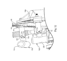
- FIG. 12 is a perspective view of a locking mechanism for the links on the bow press of FIG. 4 .
- FIG. 13 is a bottom view of a bevel gear assembly for the actuator mechanism on the bow press of FIG. 4 .
- FIG. 14 illustrates a compound bow mounted in the bow press of FIG. 4 .
- FIG. 15 illustrates deflection of the bow limbs of the bow in the bow press of FIG. 14 .
- FIG. 16 illustrates an alternate bow press in accordance with an embodiment of the present disclosure.
- FIGS. 4 through 6 illustrate an exemplary a bow press 20 in accordance with an embodiment of the present disclosure.
- the bow press 20 includes base members 22 support rail 24 along which pivot arm brackets 26 A, 26 B (“ 26 ”) are moved relative to longitudinal axis 28 using drive mechanism 30 .
- the pivot arm brackets 26 are preferably located on opposite sides of center portion 24 A of the support rail.
- the drive mechanism 30 includes handle 32 coupled to gear box 34 that rotates ball screw 36 .
- the ball screw 36 is coupled to the pivot arm brackets 26 by threaded couplings 38 A, 38 B.
- the threaded coupling 38 A preferably has left-handed threads and the right threaded coupling 38 B includes right handed threads, so the pivot arm brackets 26 move symmetrically toward or away from each other, depending on the direction the handle 32 is turned.
- An alternate mechanism for symmetrically moving the pivot arm brackets 26 is disclosed in commonly-owned U.S. Pat. No. 6,968,834 (Gibbs), which is hereby incorporated by reference.
- Pivot arms 50 A, 50 B (“ 50 ”) are pivotally attached to the respective pivot arm brackets 26 A, 26 B by pivot pins 52 A, 52 B (“ 52 ”) to permit the pivot arms 50 to move along arcs 54 A, 54 B (“ 54 ”).
- the pivot arm brackets 26 preferably include handles 40 A, 40 B (“ 40 ”) attached to threaded members 42 A, 42 B (“ 42 ”) that fix the location along the rail 24 .
- the pivot arm brackets 26 are preferably infinitely adjustable along the axis 28 .
- Spring mechanisms 27 preferably bias the pivot arms 50 away from the rail 24 .
- the spring force of the spring mechanisms 27 is preferably sufficient to suspend the pivot arms 50 in a neutral position above the rail 24 .
- the “floating” pivot arm 50 facilitates adjustment of the present bow press 20 .
- outside support members 58 A, 58 B (“ 58 ”) are attached to the pivot arm brackets 26 at a location below the inside support members 56 .
- the outside support members 58 are releasably attached to the pivot arm brackets 26 by pins 57 .
- the outside support members 56 can be slide off of support arms 59 and reversed (see e.g., FIG. 13 ) or alternate outside support members substituted.
- an outside support member 56 with a particular shape corresponding to the particular bow arms may be easily attached to the present bow press 20 .
- extension members 60 A, 60 B (“ 60 ”) that slide in ratcheting mechanisms 62 A, 62 B (“ 62 ”).
- the extension members 60 include teeth 64 that engage with edges 66 in release levers 68 .
- the levers 68 are preferably biased in the locked position by springs 70 .
- ratchet or “ratcheting” refers to a mechanism that allows continuous linear or rotary motion in only one direction while preventing motion in the opposite direction.
- the ratcheting mechanisms 62 permit the inside support members 56 to move independently in direction 74 toward outside support members 58 to capture the riser (see e.g., FIG. 14 ) or the bow limbs, such as on a crossbow.
- “riser” refers to a center member connecting a pair of discrete limbs, such as on a compound bow or a crossbow, or the center region of a traditional bow where the bow limbs are a continuous structure, such as on a laminated bow or composite bow.
- the levers 68 engage with the teeth 64 to prevent the inside support members 56 from moving in opposite direction 72 .
- the levers 68 are moved in direction 76 to disengage the edges 66 from the teeth 64 .
- handles 78 are rotate to advance threaded members 80 into the ratcheting mechanisms 62 to compressively engage with the extension members 60 .
- the threaded members 80 serve to secure the extension members 60 relative to the pivot arm brackets 26 .
- the opposing support members 56 , 58 serve to positively lock or secure the bow the press 20 (see e.g., FIGS. 14 and 15 ). Locating the opposing support members 56 , 58 on the pivot arm brackets 26 positions the opposing compressive forces F near the axis of rotation 52 of the pivot arms 50 .
- each pivot arm 50 includes a sliding linkage bracket 90 A, 90 B (“ 90 ”) that slides along axes 92 A, 92 B (“ 92 ”).
- the sliding linkage brackets 90 are preferably infinitely adjustable along the pivot arms 50 .
- Links 94 A, 94 B (“ 94 ”) are pivotally attached to the linkage brackets 90 by pivot pins 96 .
- Threaded members 98 attached to handles 100 are provided to lock or fix the linkage brackets 90 alone the axes 92 .
- the linkage brackets 90 also include shafts 102 A, 102 B (“ 102 ”) that support one or more rotating support members 104 A, 104 B (“ 104 ”).
- each rotating support member 104 is a plurality of wheels 106 A, 106 B (“ 106 ”) and 108 A, 108 B (“ 108 ”).
- the rotating support members 104 can be cam shaped, crescent shape (see e.g. FIG. 16 ), or a variety of other shapes.
- the rotating support members 104 also preferably include spokes 107 with large openings 109 to provide access to the bow limb tips and bow cams during repair.
- the wheels 106 , 108 have a diameter of about 6 inches to about 10 inches.
- the protruding portions of the shafts 102 are preferably threaded to permit gaps 110 A, 110 B (“ 110 ”) to be adjusted to correspond with the width of the bow limbs.
- the rotating support members 104 can be configured to concentrate the bending forces near the bow cam axes 208 (see FIG. 15 ), without capturing the limb tips.
- the openings 109 provide access to the bow cams during pressing.
- the links 94 slide in slots 136 A, 136 B (“ 136 ”) in locking mechanisms 120 A, 120 B (“ 120 ”) attached to bracket 148 .
- the locking mechanisms 120 include handles 122 A, 122 B (“ 122 ”) with center pins 124 A, 124 B (“ 124 ”) that are biased into engagement with holes 126 in the links 94 .
- the locking mechanism 120 is adjustable.
- the center pins 124 include protrusions 128 that can be located in one of a plurality of slots 130 A, 130 B, 130 C (“ 130 ”) that control the depth of the center pins 124 relative to the links 94 .
- the first slot 130 A retains the center pin 124 in a location disengaged from the links 94 , permitting the links 94 to move freely in the slots 136 .
- the second slot 130 B positions the center pin 124 to permit a ratcheting motion with the links 94 .
- the distal ends (not shown) of the center pins 124 include a bevel that allows a ratcheting mechanism of the links 94 to slide upward in directions 134 A, 134 B (“ 134 ”).
- the third slot 130 C retains the center pin 124 in a locked configuration that prevents the links 94 from moving.
- the links 94 are used to control the distance 149 between the bracket 148 and the linkage brackets 90 .
- the links 94 can be two-part telescoping structures.
- the telescoping feature can be used to control the distance 149 .
- the telescoping feature preferably include a ratcheting structure that permits the distance 149 to be reduced, but resists lengthening.
- actuation mechanism 140 includes a center column 142 attached to the rail 24 by bracket 144 .
- the center column 142 includes telescoping member 146 extendible and retractable along actuator axis 160 .
- the telescoping member 146 is attached to the locking mechanisms 120 by locking mechanism bracket 148 .
- the actuation mechanism 140 automatically maintains symmetry between the components 26 , 94 as the bracket 148 is moved toward and away from the support rail 24 .
- the center column 142 includes a jack screw 154 that extends and retracts the extendible member 146 relative to the rail 24 .
- the bracket 144 supports handle 150 and shaft 152 that operates bevel gear assembly 154 .
- Rotation of the handle 150 operates the jack screw 154 to raise and lower the locking mechanism bracket 148 .
- the location of the locking mechanism bracket 148 relative to the rail 24 is preferably infinitely adjustable.
- the screw jack 154 functions as an extensible force for applying bending force to the limbs of a bow mounted in the bow press 20 .
- FIGS. 14 and 15 Operation of the exemplary embodiment of the bow press 20 is illustrated in FIGS. 14 and 15 .
- the bow 200 in either a strung or an unstrung condition, is placed into the bow press 20 , generally in the orientation shown.
- bow limbs 202 are in an extended configuration.
- the handle 32 is rotated to position the pivot arm brackets 26 relative to riser 204 on the bow 200 .
- the inside support members 56 are moved in the direction 74 until the riser 204 is compressively engaged against the outside support members 58 .
- Compressive forces F serve to positively lock the bow 200 to the pivot arm brackets 26 .
- the ratcheting mechanisms 62 retain the inside support members 56 in the compressed configuration (see FIG. 7 ).
- Handles 78 are rotated to lock the inside support members 56 in position (see FIG. 7 ).
- the sliding linkage brackets 90 are slid along the pivot arms 50 (see FIG. 12 ) until the rotating support members 104 are positioned at the correct position relative to the limbs 202 .
- the rotating support members 104 preferably engage the limbs 202 proximate the bow cam axes 208 , preferably within two inches of the bow cam axes 208 .
- the wheels 106 , 108 are rotated on threaded shafts 102 to set the desired gap 110 for width of the limbs 202 .
- the handles 100 are then rotated to lock the sliding linkage brackets 90 in position.
- the intersection point between the links 94 relative to the bracket 148 may also be adjusted to bring the rotating support members 104 into contact with the limbs 202 .
- Handles 156 A, 156 B (“ 156 ”) are provided to adjust the positions of the pivot arms 50 .
- the handled 150 is then rotated to extend the jack screw 154 in direction 160 , displacing the bracket 148 away from the support rail 24 and bending the limbs 202 , as illustrated in FIG. 15 .
- the displacement of the bracket 148 is translated by the links 94 as force 170 on the bow limbs 202 .
- the rotating support members 104 roll along the bow limbs 202 to provide a smooth transition between the extended configuration in FIG. 14 to the bent configuration in FIG. 15 . As the limbs 202 are bent inward, the tension on bow string 206 is relaxed.
- the rotating support members 104 preferably engage the limbs 202 on opposite sides of the bow cam axes 208 or within 2 inches of the bow cam axes 208 . Concentrating the bending forces near the bow cam axes 208 distributes the force 170 along substantially the full length of the limbs 202 , reducing the chance of damage to the limbs 202 .
- the configuration of FIG. 15 simulates the forces applied to the bow 200 during normal usage.
- the handled 150 is turned in the opposite direction to retract the jack screw 154 to a point that the limbs 202 are in the extended position illustrated in FIG. 14 , and the bow 200 can be removed from the bow press 20 .
- a bow press in accordance with the disclosure provides significant advantages that greatly facilitate repair and adjustment of compound bows.
- the support members 56 , 58 positively secure the bow 200 to the bow press 20 .
- the adjustable gap 110 between the wheels 106 , 108 concentrates the bending force near the axes 208 of the bow cams 210 to facilitate bending the limbs 202 without damaging the bow 200 .
- the various ratcheting systems permit a single person to mount the bow 200 in the press 20 .
- FIG. 16 illustrates an alternate bow press 300 substantially as shown in FIG. 4 , except that the rotating support members 302 are cams or crescent shaped members.
- the outside support members 58 A, 58 B have also been rotated 180 degrees relative to the support arms 59 .
- the adjustability of the outside support members 58 permits the bow presses 20 , 300 to be used with a wide variety of bow designs, as well as many cross bows.
Landscapes
- Engineering & Computer Science (AREA)
- General Engineering & Computer Science (AREA)
- Rehabilitation Tools (AREA)
Abstract
Description
Claims (22)
Priority Applications (1)
| Application Number | Priority Date | Filing Date | Title |
|---|---|---|---|
| US13/345,168 US8851057B2 (en) | 2012-01-06 | 2012-01-06 | Bow press |
Applications Claiming Priority (1)
| Application Number | Priority Date | Filing Date | Title |
|---|---|---|---|
| US13/345,168 US8851057B2 (en) | 2012-01-06 | 2012-01-06 | Bow press |
Publications (2)
| Publication Number | Publication Date |
|---|---|
| US20130174823A1 US20130174823A1 (en) | 2013-07-11 |
| US8851057B2 true US8851057B2 (en) | 2014-10-07 |
Family
ID=48743041
Family Applications (1)
| Application Number | Title | Priority Date | Filing Date |
|---|---|---|---|
| US13/345,168 Active 2032-12-22 US8851057B2 (en) | 2012-01-06 | 2012-01-06 | Bow press |
Country Status (1)
| Country | Link |
|---|---|
| US (1) | US8851057B2 (en) |
Cited By (2)
| Publication number | Priority date | Publication date | Assignee | Title |
|---|---|---|---|---|
| US20140060513A1 (en) * | 2012-09-06 | 2014-03-06 | Kevin R. Tulpa | Archery bow press and method for compressing an archery bow using collectively connected bow limb supports |
| US20140331982A1 (en) * | 2011-05-17 | 2014-11-13 | Georgios Gouramanis | Universal archery bow press |
Families Citing this family (2)
| Publication number | Priority date | Publication date | Assignee | Title |
|---|---|---|---|---|
| CN104075621A (en) * | 2014-07-05 | 2014-10-01 | 宁波海伯精工机械制造有限公司 | Bow press |
| US10408559B2 (en) * | 2017-10-04 | 2019-09-10 | Specialty Archery, L.L.C. | Archery crossbow portable press |
Citations (25)
| Publication number | Priority date | Publication date | Assignee | Title |
|---|---|---|---|---|
| US3055655A (en) * | 1960-04-04 | 1962-09-25 | Clarence C Chelf | Device for stringing archery bows |
| US5022377A (en) * | 1990-01-08 | 1991-06-11 | Stevens Richard L | Portable bow press |
| US5125389A (en) * | 1991-01-22 | 1992-06-30 | Edwin Paff | Tensioning apparatus for compound archery bows |
| US5222473A (en) * | 1992-07-20 | 1993-06-29 | Lint Gary T | Bow press |
| US5370103A (en) * | 1993-09-10 | 1994-12-06 | Desselle; Kevin W. | Bow press |
| US5425350A (en) * | 1993-11-29 | 1995-06-20 | Egusquiza; Ralph R. | Portable bow press |
| US5433186A (en) * | 1994-03-07 | 1995-07-18 | Corwin; Clay | Bow press and method for compressing bows |
| US5983879A (en) * | 1998-06-19 | 1999-11-16 | Gifford; Craig N. | Bow mount and process for tuning a bow |
| US6220235B1 (en) * | 1999-11-22 | 2001-04-24 | William L. Sands | Bow tuning apparatus with a nock travel indicator |
| US6386190B1 (en) * | 2000-05-16 | 2002-05-14 | Gerald Kurtz, Jr. | Bow press |
| US6932070B1 (en) * | 2004-07-02 | 2005-08-23 | Gerald Kurtz, Jr. | Bow press |
| US6968834B1 (en) * | 2004-09-10 | 2005-11-29 | C. S. Gibbs Corporation | Bow press |
| US20060000462A1 (en) * | 2004-07-02 | 2006-01-05 | Kurtz Gerald Jr | Bow press having pivoted bow limb support arm |
| US7089923B2 (en) * | 2002-02-23 | 2006-08-15 | Kenneth Johnson | Universal compound bow press |
| US20060191522A1 (en) * | 2004-12-30 | 2006-08-31 | Henry Donald J | Bow press |
| US20070119438A1 (en) * | 2005-11-29 | 2007-05-31 | Pittman Leon M | Compound bow maintenance press and method for compressing a compound bow from the bow limb ends |
| US20090056688A1 (en) * | 2007-08-27 | 2009-03-05 | The Flinchbaugh Company, Inc. | Adapter for bow press |
| US20090107475A1 (en) * | 2005-11-29 | 2009-04-30 | Leon Monroe Pittman | Compound bow press with adaptable limb end fingers |
| US20100089376A1 (en) * | 2008-10-09 | 2010-04-15 | Bunk Paul H | Bow press with synchronously screw driven/pivoting outer bow limb support arms and mounted in free sliding fashion upon a support rail |
| US20110162631A1 (en) * | 2010-01-05 | 2011-07-07 | Tulpa Kevin R | Bow Press |
| US20110232616A1 (en) * | 2011-05-17 | 2011-09-29 | Georgios Gouramanis | Universal archery bow press |
| US8141546B2 (en) * | 2009-10-20 | 2012-03-27 | Poe Lang Enterprises Co., Ltd. | Bowstring drawing assembly for a bow |
| US8387600B1 (en) * | 2009-01-05 | 2013-03-05 | Charles Edward Horn | Archery bow press |
| US8505523B1 (en) * | 2010-01-05 | 2013-08-13 | Charles Edward Horn | Bow press with enhanced safety features |
| US8505526B1 (en) * | 2009-02-04 | 2013-08-13 | Mcp Ip, Llc | Archery bow |
-
2012
- 2012-01-06 US US13/345,168 patent/US8851057B2/en active Active
Patent Citations (30)
| Publication number | Priority date | Publication date | Assignee | Title |
|---|---|---|---|---|
| US3055655A (en) * | 1960-04-04 | 1962-09-25 | Clarence C Chelf | Device for stringing archery bows |
| US5022377A (en) * | 1990-01-08 | 1991-06-11 | Stevens Richard L | Portable bow press |
| US5125389A (en) * | 1991-01-22 | 1992-06-30 | Edwin Paff | Tensioning apparatus for compound archery bows |
| US5222473A (en) * | 1992-07-20 | 1993-06-29 | Lint Gary T | Bow press |
| US5370103A (en) * | 1993-09-10 | 1994-12-06 | Desselle; Kevin W. | Bow press |
| US5425350A (en) * | 1993-11-29 | 1995-06-20 | Egusquiza; Ralph R. | Portable bow press |
| US5433186A (en) * | 1994-03-07 | 1995-07-18 | Corwin; Clay | Bow press and method for compressing bows |
| US5983879A (en) * | 1998-06-19 | 1999-11-16 | Gifford; Craig N. | Bow mount and process for tuning a bow |
| US6220235B1 (en) * | 1999-11-22 | 2001-04-24 | William L. Sands | Bow tuning apparatus with a nock travel indicator |
| US6386190B1 (en) * | 2000-05-16 | 2002-05-14 | Gerald Kurtz, Jr. | Bow press |
| US7089923B2 (en) * | 2002-02-23 | 2006-08-15 | Kenneth Johnson | Universal compound bow press |
| US6932070B1 (en) * | 2004-07-02 | 2005-08-23 | Gerald Kurtz, Jr. | Bow press |
| US20060000462A1 (en) * | 2004-07-02 | 2006-01-05 | Kurtz Gerald Jr | Bow press having pivoted bow limb support arm |
| US7185644B2 (en) * | 2004-07-02 | 2007-03-06 | Kurtz Jr Gerald | Bow press having pivoted bow limb support arm |
| US6968834B1 (en) * | 2004-09-10 | 2005-11-29 | C. S. Gibbs Corporation | Bow press |
| US20060191522A1 (en) * | 2004-12-30 | 2006-08-31 | Henry Donald J | Bow press |
| US7255099B2 (en) * | 2004-12-30 | 2007-08-14 | Donald J Henry | Bow press |
| US20070119438A1 (en) * | 2005-11-29 | 2007-05-31 | Pittman Leon M | Compound bow maintenance press and method for compressing a compound bow from the bow limb ends |
| US20090107475A1 (en) * | 2005-11-29 | 2009-04-30 | Leon Monroe Pittman | Compound bow press with adaptable limb end fingers |
| US7597094B2 (en) * | 2005-11-29 | 2009-10-06 | Leon Monroe Pittman | Compound bow maintenance press and method for compressing a compound bow from the bow limb ends |
| US7644708B2 (en) * | 2005-11-29 | 2010-01-12 | Leon Monroe Pittman | Compound bow press with adaptable limb end fingers |
| US20090056688A1 (en) * | 2007-08-27 | 2009-03-05 | The Flinchbaugh Company, Inc. | Adapter for bow press |
| US20100089376A1 (en) * | 2008-10-09 | 2010-04-15 | Bunk Paul H | Bow press with synchronously screw driven/pivoting outer bow limb support arms and mounted in free sliding fashion upon a support rail |
| US8387600B1 (en) * | 2009-01-05 | 2013-03-05 | Charles Edward Horn | Archery bow press |
| US8505526B1 (en) * | 2009-02-04 | 2013-08-13 | Mcp Ip, Llc | Archery bow |
| US8141546B2 (en) * | 2009-10-20 | 2012-03-27 | Poe Lang Enterprises Co., Ltd. | Bowstring drawing assembly for a bow |
| US20110162631A1 (en) * | 2010-01-05 | 2011-07-07 | Tulpa Kevin R | Bow Press |
| US8402955B2 (en) * | 2010-01-05 | 2013-03-26 | Kevin R. Tulpa | Bow press |
| US8505523B1 (en) * | 2010-01-05 | 2013-08-13 | Charles Edward Horn | Bow press with enhanced safety features |
| US20110232616A1 (en) * | 2011-05-17 | 2011-09-29 | Georgios Gouramanis | Universal archery bow press |
Non-Patent Citations (1)
| Title |
|---|
| Apple Archery, 2011 Apple Archery Catalog Superior Archery Service & Repair Tools, pp. 1 through 7, Manchester, PA. |
Cited By (9)
| Publication number | Priority date | Publication date | Assignee | Title |
|---|---|---|---|---|
| US20140331982A1 (en) * | 2011-05-17 | 2014-11-13 | Georgios Gouramanis | Universal archery bow press |
| US9366498B2 (en) * | 2011-05-17 | 2016-06-14 | Georgios Gouramanis | Universal archery bow press |
| US20160282078A1 (en) * | 2011-05-17 | 2016-09-29 | Georgios Gouramanis | Universal archery bow press |
| US9599427B1 (en) * | 2011-05-17 | 2017-03-21 | Georgios Gouramanis | Archery bow press limb support apparatus, system and method |
| US9719750B2 (en) * | 2011-05-17 | 2017-08-01 | Georgios Gouramanis | Universal archery bow press |
| US20140060513A1 (en) * | 2012-09-06 | 2014-03-06 | Kevin R. Tulpa | Archery bow press and method for compressing an archery bow using collectively connected bow limb supports |
| US9255760B2 (en) * | 2012-09-06 | 2016-02-09 | Kevin R. Tulpa | Archery bow press and method for compressing an archery bow using collectively connected bow limb supports |
| US20160040953A1 (en) * | 2012-09-06 | 2016-02-11 | Kevin R. Tulpa | Archery bow press and method for compressing an archery bow using collectively connected bow limb supports |
| US9574842B2 (en) * | 2012-09-06 | 2017-02-21 | Kevin R. Tulpa | Archery bow press and method for compressing an archery bow using collectively connected bow limb supports |
Also Published As
| Publication number | Publication date |
|---|---|
| US20130174823A1 (en) | 2013-07-11 |
Similar Documents
| Publication | Publication Date | Title |
|---|---|---|
| TWI649531B (en) | Spiral elastic element for a shooting device | |
| US9255753B2 (en) | Energy storage device for a bow | |
| US10859341B2 (en) | Crossbow with a release mechanism | |
| US8899217B2 (en) | Bowstring cam arrangement for compound long bow or crossbow | |
| US20220205755A1 (en) | Crossbow with Pulleys that Rotate Around Stationary Axes | |
| US9494379B2 (en) | Crossbow | |
| US9494380B1 (en) | String control system for a crossbow | |
| US5022377A (en) | Portable bow press | |
| US8776770B2 (en) | Bow with adjustable limbs | |
| US8851057B2 (en) | Bow press | |
| US8499753B2 (en) | Integrated cocking device | |
| US7305979B1 (en) | Dual-cam archery bow with simultaneous power cable take-up and let-out | |
| US7913680B2 (en) | Portable bow press and limb connector therefor | |
| US10502516B2 (en) | Crossbow cam | |
| US9255760B2 (en) | Archery bow press and method for compressing an archery bow using collectively connected bow limb supports | |
| USRE47036E1 (en) | Cable guard system for archery bows | |
| US7644708B2 (en) | Compound bow press with adaptable limb end fingers | |
| US6968834B1 (en) | Bow press | |
| US8789518B2 (en) | Universal archery bow press | |
| US9261321B2 (en) | Self-tunable compound bow | |
| US7089923B2 (en) | Universal compound bow press | |
| KR101657676B1 (en) | Compound bow to adjust draw length | |
| US6659096B1 (en) | Split-buss-cable single-cam compound archery bow | |
| US9335114B2 (en) | Self-tunable compound bow | |
| KR101573845B1 (en) | Device for bow center regulation |
Legal Events
| Date | Code | Title | Description |
|---|---|---|---|
| AS | Assignment |
Owner name: FIELD LOGIC, INC., WISCONSIN Free format text: ASSIGNMENT OF ASSIGNORS INTEREST;ASSIGNORS:PULKRABEK, LARRY;ENGSTROM, JAY;PELLETT, AARON;AND OTHERS;REEL/FRAME:027494/0924 Effective date: 20120106 |
|
| STCF | Information on status: patent grant |
Free format text: PATENTED CASE |
|
| AS | Assignment |
Owner name: FL ARCHERY HOLDINGS LLC, WISCONSIN Free format text: ENTITY CONVERSION;ASSIGNOR:FIELD LOGIC INC.;REEL/FRAME:036026/0975 Effective date: 20150528 |
|
| AS | Assignment |
Owner name: ARES CAPITAL CORPORATION, AS ADMINISTRATIVE AGENT, Free format text: SECURITY INTEREST;ASSIGNOR:FL ARCHERY HOLDINGS LLC;REEL/FRAME:036091/0648 Effective date: 20150713 |
|
| FEPP | Fee payment procedure |
Free format text: PAT HOLDER NO LONGER CLAIMS SMALL ENTITY STATUS, ENTITY STATUS SET TO UNDISCOUNTED (ORIGINAL EVENT CODE: STOL); ENTITY STATUS OF PATENT OWNER: LARGE ENTITY |
|
| AS | Assignment |
Owner name: FERADYNE OUTDOORS, LLC, WISCONSIN Free format text: ASSIGNMENT OF ASSIGNORS INTEREST;ASSIGNOR:FL ARCHERY HOLDINGS LLC;REEL/FRAME:039946/0056 Effective date: 20160930 |
|
| FEPP | Fee payment procedure |
Free format text: PAYOR NUMBER ASSIGNED (ORIGINAL EVENT CODE: ASPN); ENTITY STATUS OF PATENT OWNER: LARGE ENTITY |
|
| AS | Assignment |
Owner name: OWL ROCK CAPITAL CORPORATION AS COLLATERAL AGENT, Free format text: SECURITY INTEREST;ASSIGNORS:FERADYNE OUTDOORS, LLC;RAGE OUTDOORS LLC;FL ARCHERY HOLDINGS LLC,;AND OTHERS;REEL/FRAME:042586/0202 Effective date: 20170525 Owner name: MUZZY OUTDOORS, LLC,, WISCONSIN Free format text: RELEASE BY SECURED PARTY;ASSIGNOR:ARES CAPITAL CORPORATION;REEL/FRAME:042583/0924 Effective date: 20170525 Owner name: FL ARCHERY HOLDINGS LLC, WISCONSIN Free format text: RELEASE BY SECURED PARTY;ASSIGNOR:ARES CAPITAL CORPORATION;REEL/FRAME:042583/0924 Effective date: 20170525 Owner name: FERADYNE OUTDOORS, LLC,, WISCONSIN Free format text: RELEASE BY SECURED PARTY;ASSIGNOR:ARES CAPITAL CORPORATION;REEL/FRAME:042583/0924 Effective date: 20170525 Owner name: OUT RAGE, LLC, WISCONSIN Free format text: RELEASE BY SECURED PARTY;ASSIGNOR:ARES CAPITAL CORPORATION;REEL/FRAME:042583/0924 Effective date: 20170525 |
|
| AS | Assignment |
Owner name: WELLS FARGO BANK, NATIONAL ASSOCATION, AS ABL COLL Free format text: SECURITY INTEREST;ASSIGNORS:FERADYNE OUTDOORS, LLC;RAGE OUTDOORS LLC;FL ARCHERY HOLDINGS LLC;AND OTHERS;REEL/FRAME:042587/0223 Effective date: 20170525 Owner name: OWL ROCK CAPITAL CORPORATION AS COLLATERAL AGENT, Free format text: SECURITY INTEREST;ASSIGNOR:FREEREIN LLC;REEL/FRAME:042587/0806 Effective date: 20170525 |
|
| MAFP | Maintenance fee payment |
Free format text: PAYMENT OF MAINTENANCE FEE, 4TH YEAR, LARGE ENTITY (ORIGINAL EVENT CODE: M1551) Year of fee payment: 4 |
|
| AS | Assignment |
Owner name: ACQUIOM AGENCY SERVICES, MINNESOTA Free format text: SECOND LIEN INTELLECTUAL PROPERTY SECURITY AGREEMENT;ASSIGNORS:FERADYNE OUTDOORS, LLC;EASTMAN OUTDOORS, LLC;FL ARCHERY HOLDINGS LLC;AND OTHERS;REEL/FRAME:054554/0972 Effective date: 20201130 |
|
| FEPP | Fee payment procedure |
Free format text: 7.5 YR SURCHARGE - LATE PMT W/IN 6 MO, LARGE ENTITY (ORIGINAL EVENT CODE: M1555); ENTITY STATUS OF PATENT OWNER: LARGE ENTITY |
|
| MAFP | Maintenance fee payment |
Free format text: PAYMENT OF MAINTENANCE FEE, 8TH YEAR, LARGE ENTITY (ORIGINAL EVENT CODE: M1552); ENTITY STATUS OF PATENT OWNER: LARGE ENTITY Year of fee payment: 8 |
|
| AS | Assignment |
Owner name: WAC EM BROADHEADS, LLC, WISCONSIN Free format text: RELEASE OF INTELLECTUAL PROPERTY SECURITY AGREEMENTS;ASSIGNOR:WELLS FARGO BANK, NATIONAL ASSOCIATION;REEL/FRAME:069715/0656 Effective date: 20241213 Owner name: OUTDOOR PRODUCT INNOVATIONS ACQUISITION, LLC, WISCONSIN Free format text: RELEASE OF INTELLECTUAL PROPERTY SECURITY AGREEMENTS;ASSIGNOR:WELLS FARGO BANK, NATIONAL ASSOCIATION;REEL/FRAME:069715/0656 Effective date: 20241213 Owner name: COVERT SCOUTING CAMERAS, LLC (F/K/A COVERT ACQUISITION CO., LLC), WISCONSIN Free format text: RELEASE OF INTELLECTUAL PROPERTY SECURITY AGREEMENTS;ASSIGNOR:WELLS FARGO BANK, NATIONAL ASSOCIATION;REEL/FRAME:069715/0656 Effective date: 20241213 Owner name: FREEREIN LLC, WISCONSIN Free format text: RELEASE OF INTELLECTUAL PROPERTY SECURITY AGREEMENTS;ASSIGNOR:WELLS FARGO BANK, NATIONAL ASSOCIATION;REEL/FRAME:069715/0656 Effective date: 20241213 Owner name: EASTMAN OUTDOORS, LLC, WISCONSIN Free format text: RELEASE OF INTELLECTUAL PROPERTY SECURITY AGREEMENTS;ASSIGNOR:WELLS FARGO BANK, NATIONAL ASSOCIATION;REEL/FRAME:069715/0656 Effective date: 20241213 Owner name: MUZZY OUTDOORS, LLC, WISCONSIN Free format text: RELEASE OF INTELLECTUAL PROPERTY SECURITY AGREEMENTS;ASSIGNOR:WELLS FARGO BANK, NATIONAL ASSOCIATION;REEL/FRAME:069715/0656 Effective date: 20241213 Owner name: FIELD LOGIC, LLC, WISCONSIN Free format text: RELEASE OF INTELLECTUAL PROPERTY SECURITY AGREEMENTS;ASSIGNOR:WELLS FARGO BANK, NATIONAL ASSOCIATION;REEL/FRAME:069715/0656 Effective date: 20241213 Owner name: FL ARCHERY HOLDINGS LLC, WISCONSIN Free format text: RELEASE OF INTELLECTUAL PROPERTY SECURITY AGREEMENTS;ASSIGNOR:WELLS FARGO BANK, NATIONAL ASSOCIATION;REEL/FRAME:069715/0656 Effective date: 20241213 Owner name: RAGE OUTDOORS LLC, WISCONSIN Free format text: RELEASE OF INTELLECTUAL PROPERTY SECURITY AGREEMENTS;ASSIGNOR:WELLS FARGO BANK, NATIONAL ASSOCIATION;REEL/FRAME:069715/0656 Effective date: 20241213 Owner name: FERADYNE OUTDOORS, LLC, WISCONSIN Free format text: RELEASE OF INTELLECTUAL PROPERTY SECURITY AGREEMENTS;ASSIGNOR:WELLS FARGO BANK, NATIONAL ASSOCIATION;REEL/FRAME:069715/0656 Effective date: 20241213 |
|
| AS | Assignment |
Owner name: SIENA LENDING GROUP LLC, CONNECTICUT Free format text: SECURITY INTEREST;ASSIGNORS:FERADYNE OUTDOORS, LLC;FIELD LOGIC, LLC;MUZZY OUTDOORS, LLC;AND OTHERS;REEL/FRAME:069736/0254 Effective date: 20241213 |