US8850753B2 - Apparatus for establishing a paver surface over a subsurface - Google Patents
Apparatus for establishing a paver surface over a subsurface Download PDFInfo
- Publication number
- US8850753B2 US8850753B2 US13/564,628 US201213564628A US8850753B2 US 8850753 B2 US8850753 B2 US 8850753B2 US 201213564628 A US201213564628 A US 201213564628A US 8850753 B2 US8850753 B2 US 8850753B2
- Authority
- US
- United States
- Prior art keywords
- paver
- cap
- assembly
- key
- receptacle
- Prior art date
- Legal status (The legal status is an assumption and is not a legal conclusion. Google has not performed a legal analysis and makes no representation as to the accuracy of the status listed.)
- Active - Reinstated
Links
- 125000006850 spacer group Chemical group 0.000 claims description 46
- 230000000717 retained effect Effects 0.000 claims description 14
- 238000000034 method Methods 0.000 abstract description 18
- 230000000712 assembly Effects 0.000 description 37
- 238000000429 assembly Methods 0.000 description 37
- 239000000463 material Substances 0.000 description 8
- 230000007613 environmental effect Effects 0.000 description 7
- 239000000758 substrate Substances 0.000 description 5
- 230000003028 elevating effect Effects 0.000 description 4
- -1 polypropylene Polymers 0.000 description 4
- 230000007246 mechanism Effects 0.000 description 3
- 239000004698 Polyethylene Substances 0.000 description 2
- 239000004743 Polypropylene Substances 0.000 description 2
- 238000004873 anchoring Methods 0.000 description 2
- 239000000919 ceramic Substances 0.000 description 2
- 239000002131 composite material Substances 0.000 description 2
- 238000004519 manufacturing process Methods 0.000 description 2
- 229910052751 metal Inorganic materials 0.000 description 2
- 239000002184 metal Substances 0.000 description 2
- 150000002739 metals Chemical class 0.000 description 2
- NJPPVKZQTLUDBO-UHFFFAOYSA-N novaluron Chemical compound C1=C(Cl)C(OC(F)(F)C(OC(F)(F)F)F)=CC=C1NC(=O)NC(=O)C1=C(F)C=CC=C1F NJPPVKZQTLUDBO-UHFFFAOYSA-N 0.000 description 2
- 239000004033 plastic Substances 0.000 description 2
- 229920003023 plastic Polymers 0.000 description 2
- 229920000573 polyethylene Polymers 0.000 description 2
- 229920000642 polymer Polymers 0.000 description 2
- 229920001155 polypropylene Polymers 0.000 description 2
- 229920000915 polyvinyl chloride Polymers 0.000 description 2
- 239000004800 polyvinyl chloride Substances 0.000 description 2
- 230000004308 accommodation Effects 0.000 description 1
- 239000011449 brick Substances 0.000 description 1
- 230000007812 deficiency Effects 0.000 description 1
- 238000011161 development Methods 0.000 description 1
- 230000000694 effects Effects 0.000 description 1
- 230000003993 interaction Effects 0.000 description 1
- 230000001788 irregular Effects 0.000 description 1
- 238000005259 measurement Methods 0.000 description 1
- 238000012986 modification Methods 0.000 description 1
- 230000004048 modification Effects 0.000 description 1
- 230000000704 physical effect Effects 0.000 description 1
- 238000011160 research Methods 0.000 description 1
- XLYOFNOQVPJJNP-UHFFFAOYSA-N water Substances O XLYOFNOQVPJJNP-UHFFFAOYSA-N 0.000 description 1
- 238000004078 waterproofing Methods 0.000 description 1
Images


Classifications
-
- E—FIXED CONSTRUCTIONS
- E04—BUILDING
- E04F—FINISHING WORK ON BUILDINGS, e.g. STAIRS, FLOORS
- E04F15/00—Flooring
- E04F15/02—Flooring or floor layers composed of a number of similar elements
- E04F15/024—Sectional false floors, e.g. computer floors
- E04F15/02447—Supporting structures
- E04F15/02464—Height adjustable elements for supporting the panels or a panel-supporting framework
-
- E—FIXED CONSTRUCTIONS
- E04—BUILDING
- E04D—ROOF COVERINGS; SKY-LIGHTS; GUTTERS; ROOF-WORKING TOOLS
- E04D11/00—Roof covering, as far as not restricted to features covered by only one of groups E04D1/00 - E04D9/00; Roof covering in ways not provided for by groups E04D1/00 - E04D9/00, e.g. built-up roofs, elevated load-supporting roof coverings
- E04D11/005—Supports for elevated load-supporting roof coverings
- E04D11/007—Height-adjustable spacers
-
- E—FIXED CONSTRUCTIONS
- E04—BUILDING
- E04F—FINISHING WORK ON BUILDINGS, e.g. STAIRS, FLOORS
- E04F15/00—Flooring
- E04F15/02—Flooring or floor layers composed of a number of similar elements
- E04F15/024—Sectional false floors, e.g. computer floors
- E04F15/02447—Supporting structures
- E04F15/02452—Details of junctions between the supporting structures and the panels or a panel-supporting framework
-
- E—FIXED CONSTRUCTIONS
- E04—BUILDING
- E04F—FINISHING WORK ON BUILDINGS, e.g. STAIRS, FLOORS
- E04F15/00—Flooring
- E04F15/02—Flooring or floor layers composed of a number of similar elements
- E04F15/024—Sectional false floors, e.g. computer floors
- E04F15/02447—Supporting structures
- E04F15/02464—Height adjustable elements for supporting the panels or a panel-supporting framework
- E04F15/0247—Screw jacks
- E04F15/02482—Screw jacks with a variable angle between panel and support
Definitions
- the present application is in the field of methods and apparatus for establishing a paver surface.
- the present application is also in the field of methods and apparatus for elevating a paver surface with respect to a subsurface and/or compensating for the slope of the subsurface.
- a surface may be established over a subsurface to, in effect, adjust the aesthetic and/or physical properties of the subsurface.
- a surface is established via placing an array of pavers onto the subsurface.
- pavers are, for example, items for covering a subsurface and may include, without being limited to, tiles, stones, bricks, molded concrete, and/or the like. Therefore, there is a need for an apparatus and related methods which facilitate the placement of a paver array onto a subsurface.
- the aesthetic appearance of a paver surface can depend on the spacing, shape, and orientation of the component pavers. Notably, a surface comprising a tessellated array of pavers will typically be more aesthetically pleasing when the component pavers are evenly and uniformly spaced and oriented. For this reason, there is a need for an apparatus and related methods which facilitate the placement of a paver array onto a subsurface with even and uniform spacing and orientation.
- the disclosed apparatus in operation: receive a corner of a square paver within each quadrant until the received pavers abut the projections whereby the received pavers are uniformly spaced; and, orient the pavers via rotating the entire apparatus, typically before the pavers are received, until the received pavers are aligned with the desired paver surface array. While such apparatus are suitable for spacing square pavers, the subject apparatus are not adequate since non-square pavers are often used when constructing a paver surface. Furthermore, shifting the entire apparatus to orient the paver array may be tedious. To improve upon the above mentioned limitations, apparatus are known which feature detachable projections whereby the orientation of the pavers may be manipulated via merely orienting the attachment of the detachable projections.
- the disclosed apparatus may elevate a paver surface via stacking a plurality of apparatus in vertical alignment before placing the paver array thereon. While such manner of paver surface elevation may be suitable for incremental increases in surface levels, stacking apparatus in the described manner is limiting of the ultimate height to which the stack may raise the surface since the base apparatus features the same dimensions as the top-most apparatus in the stack.
- Stacking apparatus to increase paver surface elevation is also limited because the exact adjustment of paver surface height depends on the thickness of the individual apparatus within the stack (i.e., exact adjustment of paver surface height requires multiple apparatus of different thickness or the shaving-off of apparatus thickness).
- apparatus which feature: screw jack mechanisms (see e.g., U.S. Pat. No. 3,223,415 (issued Dec. 14, 1965), U.S. Pat. No. 3,318,057 (issued May 9, 1967), U.S. Pat. No. 5,588,264 (issued Dec. 31, 1996), and U.S. Pat. No. 6,332,292 (issued Dec. 25, 2001)); telescoping pedestal (see e.g., U.S. Pat.
- Screw-jack mechanisms are not completely satisfactory for raising the height of a paver surface since screw jack mechanisms are expensive to fabricate and the surface height cannot be increased beyond two-times the apparatus thickness without the addition of multiple components. See, e.g., U.S. Pat. No. 5,588,264, FIG. 4; see also US20080105172 (published. May 8, 2008) wherein multiple component screw jacks are combined to increase overall height.
- a telescoping pedestal is unsatisfactory because it requires the manufacture of different sized levels or complex assembly methods (see e.g., U.S. Pat. No. 4,570,397 wherein a fill is added).
- Central riser designs are not adequate because accommodations cannot be made for inaccurate measurements or unanticipated changes in desired paver heights. Further, central riser designs are inadequate because such designs often require the existence of multiple distinct components for supporting the central riser, including base and cap members, which are expensive and tedious to fabricate due to the requirement of differing molds or other fabrication tools. Accordingly, there is a need for an apparatus and related methods which facilitate the elevated and leveled placement of a paver array onto a subsurface with even and uniform spacing and orientation.
- apparatus which feature: cooperating twist slope adjustment (see e.g., U.S. Pat. No. 6,332,292); concave/convex interacting surfaces (see e.g., U.S. Pat. No. 3,318,057).
- Twist slope manipulation has not been suitable for compensating for a sloping subsurface because it only allows for slope adjustment at the paver support surface without permitting adjustment at the apparatus base.
- Concave/convex surface slope compensation is not adequate since the concave/convex surface interactions are relatively frictionless and unstable and therefore require additional components to keep the paver support surface from shifting orientation. See U.S.
- none of the heretofore known apparatus for elevating, leveling, and/or orienting a paver surface disclose a single component for accomplishing the referenced functionalities.
- apparatus heretofore known for establishing a paver surface require multiple and diverse components while yet only providing a fraction of the referenced functionalities.
- None of the heretofore known apparatus can adjust for slope, orient and space a paver, vertically support a paver surface while being composed of multiple like components for providing the recited functionalities. Accordingly, there is a need for an improved apparatus for establishing a paver surface without the deficiencies of apparatus which are presently known.
- assemblies may be for establishing a level paver support surface; for adjusting the height of a paver support surface; for manipulating the slope of a paver support surface with respect to a subsurface; and for receiving attachments for orienting and spacing adjacent pavers.
- the assembly may comprise: a base; a concave surface; a cap with a convex surface and a paver support surface; and, a key for maintaining an interface between the concave and convex surface.
- the assembly may further comprise: a threaded collar threaded with a threaded insert with a concave surface; and wherein the key is for maintaining an interface between the second concave and the convex surfaces.
- the assembly may be for establishing an elevated and slope adjusted surface.
- the assembly may be for elevating and leveling a paver surface. Further disclosed are exemplary methods of establishing a paver surface.
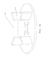
- FIG. 1A is a perspective view of the first embodiment of an assembly 1000 ;
- FIG. 1B is an exploded view of the first embodiment of the assembly 1000 ;
- FIG. 2A is a top perspective view of a base 1100 ;
- FIG. 2B is a bottom perspective view of the base 1100 ;
- FIG. 2C is a top plan view of the base 1100 ;
- FIG. 2D is a bottom plan view of the base 1100 ;
- FIG. 2E is a side profile view of the base 1100 ;
- FIG. 3A is a top perspective view of a cap 1200 ;
- FIG. 3B is a bottom perspective view of the cap 1200 ;
- FIG. 3C is a top plan view of the cap 1200 ;
- FIG. 3D is a bottom plan view of the cap 1200 ;
- FIG. 3E is a side profile view of the cap 1200 ;
- FIG. 4A is a top perspective view of a key 1300 ;
- FIG. 4B is a bottom perspective view of the key 1300 ;
- FIG. 4C is a side profile view of the key 1300 ;
- FIG. 5A is a top perspective view of a spacer 1400 ;
- FIG. 5B is a bottom perspective view of the spacer 1400 ;
- FIG. 5C is a top plan view of the spacer 1400 ;
- FIG. 5D is a bottom plan view of the spacer 1400 ;
- FIG. 5E is a side profile view of the spacer 1400 ;
- FIG. 6A is a top perspective view of a buffer 1500 ;
- FIG. 6B is a bottom perspective view of the buffer 1500 ;
- FIG. 6C is a top plan view of the buffer 1500 ;
- FIG. 6D is a bottom plan view of the buffer 1500 ;
- FIG. 6E is a side profile view of the buffer 1500 ;
- FIG. 7 depicts a side view of the assembly 1000 and illustrates one mode establishing a leveled surface
- FIG. 8A is a perspective view of the second embodiment of an assembly 2000 in a first configuration
- FIG. 8B is a perspective view of the second embodiment of the assembly 2000 in a second configuration
- FIG. 8C is an exploded view of the second embodiment of the assembly 2000 ;
- FIG. 9A is a top perspective view of a threaded collar 2100 ;
- FIG. 9B is a bottom perspective view of the threaded collar 2100 ;
- FIG. 9C is a top plan view of the threaded collar 2100 ;
- FIG. 9D is a bottom plan view of the threaded collar 2100 ;
- FIG. 9E is a side profile view of the threaded collar 2100 ;
- FIG. 10A is a top perspective view of a threaded insert 2200 ;
- FIG. 10B is a bottom perspective view of the threaded insert 2200 ;
- FIG. 10C is a top plan view of the threaded insert 2200 ;
- FIG. 10D is a bottom plan view of the threaded insert 2200 ;
- FIG. 10E is a side profile view of the threaded insert 2200 ;
- FIG. 11 depicts a side view of the second embodiment of the assembly 2000 and illustrates one mode establishing such leveled surface
- FIG. 12A is a top perspective view of an arm 2300 ;
- FIG. 12B is a bottom perspective view of the arm 2300 ;
- FIG. 12C is a top plan view of the arm 2300 ;
- FIG. 12D is a bottom plan view of the arm 2300 ;
- FIG. 12E is a side profile view of the arm 2300 ;
- FIG. 13 is an environmental view of the arm 2300 used for fixing the space between two assemblies 1000 , 2000 ;
- FIG. 14 is a side view of the third embodiment of an assembly 3000 ;
- FIG. 15 is an exploded view of the third embodiment of the assembly 3000 ;
- FIG. 16A is a top perspective view of a base 3100 ;
- FIG. 16B is a top plan view of the base 3100 ;
- FIG. 16C is a bottom plan view of the base 3100 ;
- FIG. 16D is a side profile view of the base 3100 ;
- FIG. 17A is a top perspective view of a cap 3200 ;
- FIG. 17B is a bottom perspective view of the cap 3200 ;
- FIG. 17C is a top plan view of the cap 3200 ;
- FIG. 17D is a bottom plan view of the cap 3200 ;
- FIG. 17E is a side profile view of the cap 3200 ;
- FIG. 18 is a top perspective view of an alternate embodiment of a cap 3400 ;
- FIG. 19A is a top perspective view of a threaded insert 3500 ;
- FIG. 19B is a top plan view of the threaded insert 3500 ;
- FIG. 19C is a side profile view of the threaded insert 3500 ;
- FIGS. 20A and 20B depicts a side cross-section view of the third embodiment of the assembly 3000 and illustrates one mode establishing a leveled surface
- FIG. 21A is a side view of an assembly 4000 ;
- FIG. 21B is an exploded view of the assembly 4000 ;
- FIG. 22A is a top perspective view of a threaded collar 4100 ;
- FIG. 22B is a bottom plan view of the threaded collar 4100 ;
- FIG. 22C is a side view of the threaded collar 4100 ;
- FIG. 23A through 23 C are views of a top surface of a spacer 2400 ;
- FIG. 24 is a view of a top surface of a spacer 3400 ;
- FIGS. 25A and 25B are respectively a view of an anchoring washer for securing wooden tiles and an environmental view of the same;
- FIGS. 26A and 26B are respectively views of a top surface of a spacer 4400 and environmental views of the same;
- FIGS. 27A and 27B are respectively views of a top surface of a pipe riser spacer 5400 .
- FIG. 28 is a top perspective view of a receptacle for an arm.
- FIGS. 29A , 29 B, 29 C and 29 D are a perspective views and top environmental views of a spacer 6400 .
- preferred embodiments of the present disclosure may be assemblies of components for facilitating the elevated and leveled placement of a paver array onto a subssurface.
- the disclosed assemblies may be apparatus for supporting a paver surface or may interact with assembly components for establishing an elevated and slope adjusted surface.
- the assemblies may suitably incorporate a riser to produce an apparatus for elevating and leveling a paver surface.
- the disclosed assemblies may receive attachments for orienting and spacing an array of pavers to be supported by the assemblage.
- Other embodiments of the present disclosure may be methods of establishing a paver surface using the assemblies. The details of the preferable assemblies are best disclosed by reference to FIGS. 1 through 28E .
- FIGS. 1A and 1B depict a first embodiment of an assembly 1000 for facilitating the elevated and leveled placement of a paver array onto a substrate.
- FIG. 1A is a perspective view of the assembly 1000 and FIG. 1B is an exploded view of the same.
- the assembly 1000 comprises: a base 1100 ; a cap 1200 ; a pin 1300 ; and, a tile spacer 1400 .
- FIGS. 2A through 2E depict different views of a preferable embodiment of the base 1100 component of the assembly 1000 depicted in FIGS. 1A and 1B .
- FIGS. 2A through 2E respectively depict a top perspective, bottom perspective, top plan, bottom plan, and side profile view of the base 1100 .
- the base 1100 is generally a truncated cylinder and may comprise: a foot 1110 ; a support cylinder 1120 ; a riser socket 1130 around the cylinder 1120 ; a concave surface 1140 defining the top of the cylinder 1120 ; and a key socket 1150 through the concave surface 1140 along the axis of the cylinder 1120 .
- FIGS. 3A through 3E depict different views of a preferable embodiment of the cap 1200 component of the assembly 1000 depicted in FIGS. 1A and 1B .
- FIGS. 3A through 3 E respectively depict a top perspective, bottom perspective, top plan, bottom plan, and side profile view of the cap 1200 .
- the cap 1200 is generally a disc with a convex surface on its bottom side. Still referring to FIGS.
- the cap 1200 may comprise: a paver support surface 1210 ; a cylinder 1220 extending from the bottom of the paver support surface 1210 ; a convex surface 1230 defining the bottom of the cylinder 1220 ; a tile spacer receptacle 1240 that is coaxial to the tile support surface 1210 ; and, a key socket access hole 1250 through the convex surface 1140 along the axis of the cylinder 1220 .
- FIGS. 4A through 4C depict different views of a preferable embodiment of the key 1300 component of the assembly 1000 depicted in FIGS. 1A and 1B .
- FIGS. 4A through 4C respectively depict a top perspective, bottom perspective, and side profile view of the key 1300 .
- the key 1300 is generally an elongated x-shaped member 1310 with a flange 1320 .
- the elongated x-shaped member 1310 features locking lugs 1311 at its lower end and the flange 1320 features a coaxial wrench socket 1321 .
- FIGS. 5A through 5E depict different views of a preferable embodiment of the tile spacer 1400 component of the assembly 1000 depicted in FIGS. 1A and 1B .
- FIGS. 5A through 5E respectively depict a top perspective, bottom perspective, top plan, bottom plan, and side profile view of the spacer 1400 .
- the spacer 1400 is generally a disc that features projections 1410 that operate to divide the paver support surface 1230 of the cap 1200 into evenly spaced paver receptacles whereby pavers provided to the assembly 1000 may be uniformly oriented and spaced.
- FIG. 1B shows a preferable method for assembling the assembly 1000 .
- the base 1100 may be positioned so that the bottom side of the foot 1110 interfaces with a subsurface and wherein the cylinder 1120 extends outwardly and transversely relative to a plane of the subsurface.
- the cap 1200 may be positioned on top of the cylinder 1120 of the base 1100 so that the concave surface 1140 of the base interfaces with the convex surface 1230 of the cap 1200 and wherein the key socket 1150 of the base 1100 is located within the key socket receptacle 1250 .
- the x-shaped member 1310 of the key 1300 may be inserted through the key socket receptacle 1250 and into the key socket 1150 until the locking teeth 1151 inside the key socket 1150 interact with the locking lug 1311 of the key 1300 so that: (1) the key 1300 is retained inside the key socket 1150 ; and (2) the cap 1200 is movably (e.g., slidably and/or rotatably) retained between the flange 1320 of the key 1300 and the concave surface 1140 of the base 1100 .
- the tile spacer 1400 may be provided to the spacer receptacle 1240 of the cap 1200 whereby the spacer 1400 surface and the support surface 1230 of the cap 1200 generally form a plane.
- a paver may be supported above a subsurface via: positioning an assembly 1000 , foot 1110 down, on the subsurface; rotating the cap 1200 around the key 1300 until the orientation of the projections 1410 of the spacer 1400 align with a planned paver surface; and providing a corner of the paver to the paver support surface 1230 whereby the sides of the paver abut the projections 1410 . See FIG. 9 wherein the depicted pavers are supported, spaced, and oriented by an assembly 1000 with projections 1410 .
- the attachment may feature less or more projections 1410 to accommodate the orientation and spacing of non-square pavers.
- the projections 1410 may feature perforations (not shown) whereby the projections 1410 may be individually removed from the spacer 1400 .
- two of the four projections 1411 may be removed from the attachment whereby the side of a square paver, instead of its corner, may be received by the paver support surface 1240 of the cap 1200 .
- the dimensions of the assembly 1000 will vary with the size of the paver to be retained by the paver support surface 1230 .
- the height of the projections may vary depending on the thickness of a paver, e.g. in a range of about 0 to 20 inches.
- top and bottom or “lower” and “upper”, or any other orientation defining term should in no way be construed as limiting of the possible orientations of the assembly 1000 (i.e., the assembly may be positioned sideways, or in reversed vertical orientations even though the specification refers to a “top” and “bottom” parts).
- the foot 1110 of is adapted to support the assembly 1000 on a substrate or subsurface.
- the substrate may be sensitive and require a larger footprint than that provided by the foot 1110 .
- the substrate may feature a waterproofing means that may be punctured by the weight of a paver on the assembly 1000 .
- the foot print of the foot 1110 may be supplemented with a buffer, 1500 as best depicted in FIGS. 6A , through 6 E, which respectively depict a top perspective, bottom perspective, top plan, bottom plan, and side profile view of the buffer 1500 . Referring to FIGS.
- the buffer 1500 may generally be a disc with an upward projection 1510 of slightly larger plan than the plan of foot 1110 of the assembly 1000 whereby the foot 1110 may be retained therein and where the disc of the buffer 1500 distributes the footprint of the assembly 1000 over a wider area.
- the underside of the foot 1110 as seen in FIG. 2D , features tenons 1111 which may cooperate with mortise 1520 , shown in FIG. 6 A, so that the assembly may be positioned on the buffer 1500 with greater stability.
- Other features of the buffer 1500 will be set forth in greater detail below.
- the disclosed assembly may be used for establishing a level paver surface over a sloped subsurface.
- FIG. 7 depicts a side view of the assembly 1000 and illustrates one mode establishing such leveled surface.
- the base 1100 suitably features a concave surface 1140 and the cap 1200 suitably features a convex surface whereby the slope of the paver support surface 1230 may be skewed in any direction relative to the plane of the foot 1110 of the base 1100 via sliding the convex surface 1230 of the cap 1200 along the concave surface 1140 of the base 1100 .
- the paver support surfaces 1230 of four assemblies 1000 positioned at the four corners of a square paver will self level with respect to one another under the weight of the pavers installed thereon the assemblies 1000 .
- FIGS. 8A through 8C depict a second embodiment of an assembly 2000 for facilitating the elevated and leveled placement of a paver array onto a subsurface.
- FIG. 8A is a perspective view of the assembly 2000 in a first configuration
- FIG. 8B is a perspective view of the assembly 2000 in a second configuration
- FIG. 8C is an exploded view of the assembly 2000 .
- the assembly 2000 like the assembly of FIGS. 1A and 1B , comprises: a base 1100 ; a cap 1200 ; a key 1300 ; and, a tile spacer 1400 .
- the structure and operability of those components are the same as described above in connection with the first embodiment of an assembly 1000 .
- the assembly 2000 further comprises a female threaded collar 2100 ; and a male threaded insert 2200 .
- FIGS. 9A through 9E depict different views of a preferable embodiment of the threaded collar 2100 component of the apparatus 2000 depicted in FIGS. 8A through 8C .
- FIGS. 9A through 9E respectively depict a top perspective, bottom perspective, top plan, bottom plan, and side profile view of the threaded collar 2100 .
- the threaded collar 2100 is generally a truncated tubiform with; a grip flange 2110 ; female threads 2120 on the inside of its tubiform; and a foot 2130 .
- FIGS. 10A through 10E depict different views of a preferable embodiment of the threaded insert 2200 component of the apparatus 2000 depicted in FIGS. 8A through 8C .
- FIGS. 10A through 10E respectively depict a top perspective, bottom perspective, top plan, bottom plan, and side profile view of the threaded insert 2200 .
- the threaded insert is generally a truncated cylinder and may comprise: a foot 2210 ; a male threads 2220 on the outside surface of its cylinder shape; a concave surface 2240 defining the top of the cylinder; and a key socket 2250 through the concave surface 2240 along the axis of the cylinder.
- FIG. 8C shows a preferable method for assembling the first embodiment of the assembly 1000 .
- the base 1100 may be positioned so that the bottom side of the foot 1110 interfaces with a subsurface and wherein the cylinder 1120 extends outwardly and transversely relative to a plane of the subsurface.
- a riser 4200 e.g., a pipe section
- the foot 2130 of the threaded collar 2100 may be provided to the top of the riser 4200 so that the foot 2130 of the threaded collar 4100 is positioned inside of the riser 4200 .
- the foot 2210 of the threaded insert 2200 may be provided to the top of the threaded collar 2100 so that the threads 2120 of the collar 2100 and the threads 2220 of the insert 2200 cooperate to drive the insert 2200 to within the tubiform of the collar 4100 .
- the foot 2210 of the threaded insert 2200 may be provided to the top of the threaded collar 2100 so that the threads 2120 of the collar 2100 and the threads 2220 of the insert 2200 cooperate to drive the insert 2200 to within the tubiform of the collar 2100 .
- the cap 1200 may be positioned on top of the threaded insert 2200 so that the concave surface 2240 of the insert 2200 interfaces with the convex surface 1230 of the cap 1200 and wherein the key socket 2250 of the insert 2200 is located within the key socket receptacle 1250 of the cap 1200 .
- the x-shaped member 1310 of the key 1300 may be inserted through the key socket receptacle 1250 and into the key socket 2250 until the locking teeth 2251 inside the key socket 2250 interact with the locking lug 1311 of the key 1310 so that: (1) the key 1300 is retained inside the key socket 2250 ; and (2) the cap 1200 is movably (e.g., slidably and/or rotatably) retained between the flange 1320 of the key 1320 and the concave surface 2240 of the threaded insert 2200 .
- the tile spacer 1400 may be provided to the spacer receptacle 1240 of the cap 1200 whereby the spacer 1400 surface and the support surface 1230 of the cap 1200 generally form a plane.
- a paver may be supported above a subsurface via: positioning an assembly 2000 , foot 1110 down, on the subsurface; rotating the cap 1200 around the key 1300 until the orientation of the projections 1410 of the spacer 1400 align with a planned paver surface; and providing a corner of the paver to the paver support surface 1230 whereby the sides of the paver abut the projections 1410 .
- the disclosed assembly may be used for establishing a level paver surface over a sloped subsurface.
- FIG. 11 depicts a side view of the second embodiment of the assembly 2000 and illustrates one mode establishing such leveled surface.
- the threaded insert 2200 suitably features a concave surface 2240 and the cap 1200 suitably features a convex surface 1230 whereby the slope of the paver support surface 1230 may be skewed in any direction relative to the plane of the foot 1110 of the base 1100 via sliding the convex surface 1230 of the cap 1200 along the concave surface 2240 of the insert 2200 .
- the paver support surfaces 1210 of four assemblies 2000 positioned at the four corners of a square paver will self level with respect to one another under the weight of the pavers installed thereon the assemblies 2000 .
- the caps 1200 of a four assembly system cannot, without more than sliding the convex surface 1230 of the cap 1200 along the concave surface 2240 of the insert 2200 , be skewed enough in the applicable direction to accomplish a level surface of a square paver because the slope of the under surface may be too drastic.
- a level paver surface may be accomplished via raising or lowering one or more of the paver support surface 1230 of the assemblies 2000 relative to one or more of the paver support surface 1230 . of the other assemblies 2000 .
- such raising or lowering of the paver support surface 2210 of an assembly 2000 may be accomplished via: (1) removing the paver spacer 1400 from the assembly cap 1200 of the assembly 2000 ; (2) inserting an wrench into the wrench receptacle 1321 of the key 1300 ; (3) griping the flange grip 2110 of the collar 2100 ; and (3) torqueing the wrench so that the key 1300 turns the insert 2200 whereby the threads of the insert 2200 and collar 2100 interact to drive the insert 2200 further into or out of the tubiform of the collar 2100 .
- a plurality of assemblies 1000 , 2000 may be used to support a paver surface. Frequently, the plurality of assemblies 1000 , 2000 must be fixedly positioned at specific locations relative to one another for supporting the paver surface.
- an arm may be provided that connects to two pavers whereby their relative positions are so fixed.
- Such an arm 2300 is depicted in FIGS. 12A through 3 .
- FIGS. 12A through 12E respectively depict a top perspective, bottom perspective, top plan, bottom plan, and side profile view of the arm 2300 .
- the arm 2300 is comprised of retractable extensions with mortise 2310 on either side.
- FIG. 13 is an environmental view of the arm 2300 used for fixing the space between two assemblies 1000 , 2000 .
- the mortise 2310 of the arm 2300 may receive tenons 2112 on the upperside of the foot 2110 of the bases 2100 of two adjacent assemblies 1000 , 2000 .
- the components of the assemblies 1000 , 2000 should preferably be fashioned out of materials that are capable of supporting the weight of a paver.
- the materials which may be acceptable for fabricating the components will typically vary according to the applicable paver to be supported thereon the assemblies 1000 , 2000 .
- such materials will be readily known to one of skill in the art, and may include, without being limited to: plastics, polymers, PVC, polypropylene, polyethylene; metals; woods; ceramics; composites and other synthetic or natural materials whether molded, extruded, stamped or otherwise fabricated.
- the components of the assemblies 1000 , 2000 being or composing a paver load bearing apparatus should preferably be dimensioned to a size that renders the assemblies 1000 , 2000 capable of retaining a paver.
- the size of a paver may vary from big to little, the physical dimensions of the components will typically vary according to the applicable paver to be supported thereon the apparatus. Depending on the circumstance, such dimensions will be readily known to one of skill in the art, and may include, without being limited to a cap having an diameter spanning of 1.36 inches. The dependence of the size and dimensions of the component apply equally well to the other aspects and parts of this disclosure.
- FIGS. 14 and 15 depict a third embodiment of an assembly 3000 for facilitating the elevated and leveled placement of a paver array onto a substrate.
- FIG. 14 is a side view of the assembly 3000 and
- FIG. 15 is an exploded view of the same.
- the assembly 3000 comprises: a base 3100 ; a threaded insert 3500 , and a cap 3200 .
- FIGS. 16A through 16D depict different views of a preferable embodiment of the base 3100 component of the assembly 3000 depicted in FIGS. 14 and 15 .
- FIGS. 16A through 16D respectively depict a top perspective, top plan, bottom plan, and side profile view of the base 3100 .
- the base is generally a truncated cylinder and may comprise: a foot 3110 ; a femininely threaded support cylinder 3120 ; and, a riser socket 3130 around the cylinder 3120 .
- FIGS. 17A through 17E depict different views of a preferable embodiment of the cap 3200 component of the assembly 3000 depicted in FIGS. 14 and 15 .
- FIGS. 17A through 17E respectively depict a top perspective, bottom perspective, top plan, bottom plan, and side profile view of the cap 3200 .
- the cap 3200 is generally a disc with a convex surface on its bottom side. Still referring to FIGS.
- the cap 3200 may comprise: a paver support surface 3210 ; a cylinder 3220 extending from the bottom of the paver support surface 3210 ; a convex surface 3230 defining the bottom of the cylinder 3220 ; a tile spacer receptacle 3240 that is coaxial to the tile support surface 3210 ; and, a key socket access hole 3250 through the convex surface 3140 along the axis of the cylinder 3220 .
- FIG. 18 depicts the tile support surface 3210 of the cap 3200 with tile spacers 3211 provided thereto.
- FIGS. 19A through 19C depict different views of a preferable embodiment of the threaded insert 3500 component of the assembly 3000 depicted in FIGS. 14 through 15 .
- FIGS. 19A through 19C respectively depict a top perspective, top plan, and side profile views of the threaded insert 3500 .
- the threaded insert is generally a truncated cylinder and may comprise: a foot 3510 ; a male threads 3520 on the outside surface of its cylinder shape; a concave surface 3540 defining the top of the cylinder 3500 ; and a key 3550 extending coaxially from the concave surface 3540 along the axis of the cylinder 3500 .
- FIGS. 14 through 19C show a preferable method for assembling the assembly 3000 .
- the base 3100 may be positioned so that the bottom side of the foot 3110 interfaces with a subsurface and wherein the cylinder 3120 extends outwardly and transversely relative to a plane of the subsurface.
- the foot 3510 of the threaded insert 3500 may be provided to the top of the base 3100 so that the threads 3120 of the base 3100 and the threads 3220 of the insert 3200 cooperate to drive the insert 3200 to within the tubiform of the base 3100 .
- the cap 3200 may be positioned on top of the threaded insert 3500 so that the concave surface 3540 of the insert 3200 interfaces with the convex surface 3230 of the cap 1200 and wherein the key 3250 of the insert 3200 is located within the key socket receptacle 3250 of the cap 3200 so that: (1) the key 3250 is retained inside the key socket 3250 ; and (2) the cap 3200 is movably (e.g., slidably and/or rotatably) retained between the flange of the key 3550 and the concave surface 3540 of the threaded insert 3500 .
- a paver may be supported above a subsurface via: positioning an assembly 3000 , foot 3110 down, on the subsurface; and providing a corner of the paver to the paver support surface 3230 whereby the sides of the paver abut.
- the dimensions of the assembly 3000 will vary with the size of the paver to be retained by the paver support surface 3230 .
- the height of the projections may vary depending on the thickness of a paver, e.g. in a range of about 0 to 20 inches.
- top and bottom or “lower” and “upper”, or any other orientation defining term should in no way be construed as limiting of the possible orientations of the assembly 3000 (i.e., the assembly may be positioned sideways, or in reversed vertical orientations even though the specification refers to a “top” and “bottom” parts).
- the disclosed assembly may be used for establishing a level paver surface over a sloped subsurface.
- FIGS. 20A and 20B depict side cross-section views of the assembly 3000 and illustrate one mode establishing such leveled surface.
- the base 3100 suitably features a concave surface 3140 and the cap 3200 suitably features a convex surface 3230 whereby the slope of the paver support surface 3230 may be skewed in any direction relative to the plane of the foot 3110 of the base 3100 via sliding the convex surface 3230 of the cap 3200 along the concave surface 3140 of the base 3100 .
- the paver support surfaces 3230 of four assemblies 3000 positioned at the four corners of a square paver will self level with respect to one another under the weight of the pavers installed thereon the assemblies.
- FIGS. 21A through 21B depict a fourth embodiment of an assembly 4000 for facilitating the elevated and leveled placement of a paver array onto a subsurface.
- FIG. 21A is a side view of the assembly 4000 ;
- FIG. 21B is an exploded side view of the assembly 4000 of FIG. 21A .
- the assembly 2000 like the assembly of FIGS. 14 and 15 , comprises: a base 3100 ; a threaded insert 3500 , and a cap 3200 .
- the structure and operability of those components are the same as described above in connection with the third embodiment of an assembly 3000 shown in FIGS. 14 and 15 .
- the assembly 4000 further comprises a female threaded collar 4100 and a riser 4200 .
- FIGS. 22A through 22C depict different views of a preferable embodiment of the threaded collar 4100 component of the assembly 4000 depicted in FIGS. 20A through 20B .
- FIGS. 20A through 20C respectively depict a top perspective, bottom plan, and side profile view of the threaded collar 4100 .
- the threaded collar 4100 is generally a truncated tubiform with; a grip flange 4110 ; female threads 4120 on the inside of its tubiform; and a foot 4130 .
- FIG. 21A through FIG. 22D show a preferable method for assembling the assembly 4000 .
- the base 3100 may be positioned so that the bottom side of the foot 4110 interfaces with a subsurface and wherein the cylinder 3120 extends outwardly and transversely relative to a plane of the subsurface.
- a riser 4200 e.g., a pipe section
- the foot 4130 of the threaded collar 4100 may be provided to the top of the riser 4200 so that the foot 4130 of the threaded collar 4100 is positioned inside of the riser 4200 .
- the foot 3210 of the threaded insert 3500 may be provided to the top of the threaded collar 4100 so that the threads 4120 of the collar 4100 and the threads 3220 of the insert 3200 cooperate to drive the insert 3500 to within the tubiform of the collar 4100 .
- the cap 3200 may be positioned on top of the threaded insert 3500 so that the concave surface 3240 of the insert 3500 interfaces with the convex surface 3230 of the cap 3200 and wherein the key 3250 of the insert 3500 is located within the key socket receptacle 3250 of the cap 3200 and wherein the cap 1200 is movably (e.g., slidably and/or rotatably) retained between the flange of the key 3250 and the concave surface 3240 of the threaded insert 3500 .
- the tile spacer 1400 may be provided to the spacer receptacle 3240 of the cap 3200 whereby the spacer 1400 surface and the support surface 3230 of the cap 3200 generally form a plane.
- a paver may be supported above a subsurface via: positioning an assembly 4000 , foot 3110 down, on the subsurface; rotating the cap 3200 around the key 3250 until the orientation of the projections 1410 of the spacer 1400 align with a planned paver surface; and providing a corner of the paver to the paver support surface 1230 whereby the sides of the paver abut the projections 1410 .
- the disclosed assembly may be used for establishing a level paver surface over a sloped subsurface.
- FIG. 21A depicts a side view of the assembly 2000 and illustrates one mode establishing such leveled surface.
- the threaded insert 3500 suitably features a concave surface 3240 and the cap 3200 suitably features a convex surface 3230 whereby the slope of the paver support surface 3230 may be skewed in any direction relative to the plane of the foot 3110 of the base 3100 via sliding the convex surface 3230 of the cap 3200 along the concave surface 3240 of the insert 3500 .
- the paver support surfaces 3210 of four assemblies 4000 positioned at the four corners of a square paver will self level with respect to one another under the weight of the pavers installed thereon the assemblies 2000 .
- the caps 3200 of a four assembly 3000 , 4000 system cannot, without more than sliding the convex surface 3230 of the cap 1200 along the concave surface 3540 of the insert 3500 , be skewed enough in the applicable direction to accomplish a level surface of a square paver because the slope of the under surface may be too drastic.
- a level paver surface may be accomplished via raising or lowering one or more of the paver support surface 3230 of the assemblies 3000 , 4000 relative to one or more of the paver support surface 3230 of the other assemblies 3000 , 4000 .
- such raising or lowering of the paver support surface 3210 of an assembly 3000 , 4000 may be accomplished via: (1) removing the paver spacer from the assembly cap 3200 of the assembly 3000 ; (2) inserting an wrench into the wrench receptacle 1321 of the key; (3) griping the flange grip 3110 of the collar 3100 ; and (3) torqueing the wrench so that the key 3300 turns the insert 3500 whereby the threads of the insert 3500 and collar 4100 interact to drive the insert further into or out of the tubiform of the collar 4100 .
- FIG. 23A through 23-C are views of a top surface of a spacer 2400 , wherein tiles are locked in place via a vise plate.
- FIG. 24 is a view of a top surface of a spacer 3400 , wherein a support beam is disposed between two curved walls.
- FIGS. 25A and 25B are respectively a view of an anchoring washer for securing wooden tiles and an environmental view of the same.
- FIGS. 26A and 26B are respectively views of a top surface of a spacer 4400 and environmental views of the same.
- FIGS. 27A and 27B are respectively views of a top surface of an adjustable pipe riser spacer 5400 .
- a plurality of assemblies 3000 , 4000 may be used to support a paver surface. Frequently, the plurality of assemblies 3000 , 4000 must be fixedly positioned at specific locations relative to one another for supporting the paver surface.
- an arm may be provided that connects to two pavers whereby their relative positions are so fixed.
- Such an arm may be a pipe section provided between two pipe receptacles on the foot of a base 3100 of an assembly.
- a pipe receptacle 5000 is provided in FIG. 28 .
- a pipe may be provided between two pipe receptacles to establish an arm.
- the arm may suitably be fixedly retained within the pipe receptacles via providing a screw through the side of the pipe receptacle and into a retained pipe.
- FIGS. 29A through 29D illustrate the system disclosed by U.S. Pat. No. 8,128,312 (generally disclosed at http://silcasystem.com/ or http://www.pierdex.com/) might be incorporated into the above described system.
- the components of the assemblies 1000 - 4000 should preferably be fashioned out of materials that are capable of supporting the weight of a paver.
- the materials which may be acceptable for fabricating the components will typically vary according to the applicable paver to be supported thereon the assemblies 1000 - 4000 .
- such materials will be readily known to one of skill in the art, and may include, without being limited to: plastics, polymers, PVC, polypropylene, polyethylene; metals; woods; ceramics; composites and other synthetic or natural materials whether molded, extruded, stamped or otherwise fabricated.
- the components of the assemblies 1000 - 4000 being or composing a paver load bearing apparatus should preferably be dimensioned to a size that renders the assemblies 1000 - 4000 capable of retaining a paver.
- the size of a paver may vary from big to little, the physical dimensions of the components will typically vary according to the applicable paver to be supported thereon the apparatus. Depending on the circumstance, such dimensions will be readily known to one of skill in the art, and may include, without being limited to a cap having an diameter spanning of 1.36 inches.
- the dependence of the size and dimensions of the component apply equally well to the other aspects and parts of this disclosure
- FIGS. 1 through 29D and the associated description are of illustrative importance only. In other words, the depiction and descriptions of the present invention should not be construed as limiting of the subject matter in this application. Additional modifications may become apparent to one skilled in the art after reading this disclosure.
Landscapes
- Engineering & Computer Science (AREA)
- Architecture (AREA)
- Civil Engineering (AREA)
- Structural Engineering (AREA)
- General Engineering & Computer Science (AREA)
- Floor Finish (AREA)
Abstract
Description
Claims (5)
Priority Applications (8)
| Application Number | Priority Date | Filing Date | Title |
|---|---|---|---|
| US13/564,628 US8850753B2 (en) | 2010-03-26 | 2012-08-01 | Apparatus for establishing a paver surface over a subsurface |
| AU2013207651A AU2013207651B2 (en) | 2012-08-01 | 2013-07-20 | Improved Apparatus for Establishing a Paver Surface Over a Substrate |
| CA2822305A CA2822305C (en) | 2012-08-01 | 2013-07-31 | Improved apparatus for establishing a paver surface over a subsurface |
| CA2899937A CA2899937C (en) | 2012-08-01 | 2013-07-31 | Improved apparatus for establishing a paver surface over a subsurface |
| US14/253,818 US9284693B2 (en) | 2010-03-26 | 2014-04-15 | Apparatus and related methods of paving a subsurface |
| US14/657,977 US9410296B2 (en) | 2010-03-26 | 2015-03-13 | Apparatus and related methods of paving a subsurface |
| US15/230,829 US9879385B2 (en) | 2010-03-26 | 2016-08-08 | Apparatus and related methods of paving a subsurface |
| US15/472,098 US10415191B2 (en) | 2010-03-26 | 2017-03-28 | Plant tray |
Applications Claiming Priority (2)
| Application Number | Priority Date | Filing Date | Title |
|---|---|---|---|
| US12/732,755 US8453391B2 (en) | 2010-03-26 | 2010-03-26 | Apparatus for establishing a paver over a subsurface |
| US13/564,628 US8850753B2 (en) | 2010-03-26 | 2012-08-01 | Apparatus for establishing a paver surface over a subsurface |
Related Parent Applications (1)
| Application Number | Title | Priority Date | Filing Date |
|---|---|---|---|
| US12/732,755 Continuation-In-Part US8453391B2 (en) | 2010-03-26 | 2010-03-26 | Apparatus for establishing a paver over a subsurface |
Related Child Applications (1)
| Application Number | Title | Priority Date | Filing Date |
|---|---|---|---|
| US14/253,818 Continuation-In-Part US9284693B2 (en) | 2010-03-26 | 2014-04-15 | Apparatus and related methods of paving a subsurface |
Publications (2)
| Publication Number | Publication Date |
|---|---|
| US20130219809A1 US20130219809A1 (en) | 2013-08-29 |
| US8850753B2 true US8850753B2 (en) | 2014-10-07 |
Family
ID=49001306
Family Applications (1)
| Application Number | Title | Priority Date | Filing Date |
|---|---|---|---|
| US13/564,628 Active - Reinstated US8850753B2 (en) | 2010-03-26 | 2012-08-01 | Apparatus for establishing a paver surface over a subsurface |
Country Status (1)
| Country | Link |
|---|---|
| US (1) | US8850753B2 (en) |
Cited By (22)
| Publication number | Priority date | Publication date | Assignee | Title |
|---|---|---|---|---|
| US20150117966A1 (en) * | 2012-04-16 | 2015-04-30 | Oiles Corporation | Interval adjustment device and transport device using same |
| US20150184398A1 (en) * | 2010-03-26 | 2015-07-02 | Ramin Tabibnia | Apparatus and related methods of paving a subsurface |
| USD733528S1 (en) * | 2012-05-10 | 2015-07-07 | Elmich Pte. Ltd. | Spacer for pavers |
| US9683375B2 (en) | 2015-11-13 | 2017-06-20 | United Construction Products, Inc. | Support plate system for elevated flooring tiles |
| EP3251492A1 (en) | 2016-06-02 | 2017-12-06 | Ramin Tabibnia | Plant tray |
| US9874029B2 (en) | 2015-11-13 | 2018-01-23 | United Construction Products, Inc. | Support plate system for elevated flooring tiles |
| US9879385B2 (en) | 2010-03-26 | 2018-01-30 | Ramin Tabibnia | Apparatus and related methods of paving a subsurface |
| EP3425134A1 (en) * | 2017-07-04 | 2019-01-09 | Huzhou Xinfeng Wood Plastic Composite Co., Ltd. | Slope-adjustable supporter |
| US20190368203A1 (en) * | 2018-06-05 | 2019-12-05 | Progress Profiles Spa | Support for raised floors |
| WO2019239222A1 (en) * | 2018-06-15 | 2019-12-19 | Profilitec S.P.A. Socio Unico | A support for raised floors |
| TWI735125B (en) * | 2018-11-07 | 2021-08-01 | 楊慶鐘 | Elevator set for floor plank |
| US11261609B2 (en) | 2018-10-17 | 2022-03-01 | Magia Logistica Corporation | Wind uplift resistance mechanism for outdoor flooring |
| US11408132B2 (en) | 2017-10-16 | 2022-08-09 | Nvent Services Gmbh | Pedestal mounted paver heating system |
| US11447961B2 (en) * | 2019-09-04 | 2022-09-20 | Progress Profiles Spa | Pedestal/stand for raised floors |
| US20220341192A1 (en) * | 2016-06-24 | 2022-10-27 | Apache Industrial Services, Inc. | Load Bearing Components and Safety Deck of an Integrated Construction System |
| US11761214B2 (en) | 2020-10-12 | 2023-09-19 | Cap Trac Ltd | Flooring element |
| US11976483B2 (en) | 2016-06-24 | 2024-05-07 | Apache Industrial Services, Inc | Modular posts of an integrated construction system |
| US12043965B2 (en) | 2020-12-04 | 2024-07-23 | Ramin Tabibnia | Synthetic turf system |
| US12077971B2 (en) | 2016-06-24 | 2024-09-03 | Apache Industrial Services, Inc | Connector end fitting for an integrated construction system |
| US12116779B2 (en) | 2016-06-24 | 2024-10-15 | Apache Industrial Services, Inc | Formwork system |
| US12195961B2 (en) | 2016-06-24 | 2025-01-14 | Apache Industrial Services, Inc. | Formwork system |
| US12258767B2 (en) | 2021-03-04 | 2025-03-25 | Ramin Tabibnia | Braced flooring tray support system and method |
Families Citing this family (23)
| Publication number | Priority date | Publication date | Assignee | Title |
|---|---|---|---|---|
| US9677690B2 (en) * | 2010-02-08 | 2017-06-13 | Thomas & Betts International, Llc | Multi-purpose roof-top support |
| US11002023B2 (en) * | 2013-06-14 | 2021-05-11 | Phillip Busby | Flooring support system |
| US8898999B1 (en) * | 2013-11-27 | 2014-12-02 | United Construction Products, Inc. | Restraint system for elevated surface tiles |
| US9345325B2 (en) * | 2014-01-27 | 2016-05-24 | Target Brands, Inc. | Stackable shim |
| EP2933396B1 (en) | 2014-04-15 | 2019-09-18 | Ramin Tabibnia | Elevated paver support system |
| NL2012622B1 (en) * | 2014-04-15 | 2016-05-09 | Demar Holding B V | A floor for on a deck of a vessel, a connection element thereof, a framework thereof, a vessel, and a method for assembling said floor. |
| DE102014017951A1 (en) * | 2014-09-11 | 2016-03-17 | J.H. Tönnjes Gmbh | Apparatus and method for producing a surface covering |
| DE202016001842U1 (en) * | 2015-04-01 | 2016-04-21 | Markus Rensburg | Mounting kit for the terrace construction |
| AT518610B1 (en) * | 2016-04-21 | 2018-02-15 | Franz Leitner | Support for floor slabs |
| CN107780638A (en) * | 2016-08-30 | 2018-03-09 | 孙国燕 | Multifunctional support |
| BE1024825B1 (en) * | 2016-12-15 | 2018-07-17 | Buzon Pedestal International S.A. | Support element for spacers |
| EP3563016B1 (en) | 2016-12-27 | 2021-03-10 | Marana, Andrea | Support system for raised floors |
| CN107090961A (en) * | 2017-05-10 | 2017-08-25 | 苏州优住集成家居有限公司 | Adjustable type feet and its construction method |
| US10113320B1 (en) * | 2017-11-03 | 2018-10-30 | United Construction Products, Inc. | Restraint system for elevated flooring tiles |
| US11085193B2 (en) * | 2018-04-09 | 2021-08-10 | United Construction Products, Inc. | Peripheral restraint system for elevated flooring surface |
| AU201813433S (en) * | 2018-06-08 | 2018-08-02 | Elmich Pte Ltd | Height adjustable pedestal |
| AU201813431S (en) * | 2018-06-08 | 2018-08-02 | Elmich Pte Ltd | Adjustable pedestal |
| ES2951991T3 (en) * | 2018-06-15 | 2023-10-26 | Profilitec S P A Socio Unico | Head for raised floor support |
| BE1026914B1 (en) * | 2018-12-20 | 2020-07-22 | Buzon Pedestal Int S A | Support element of a floor covering element and assembly of a support element and a connecting lug |
| USD898233S1 (en) * | 2019-01-15 | 2020-10-06 | Hanover Prest-Paving Company | Paver pedestal |
| USD898234S1 (en) * | 2019-03-05 | 2020-10-06 | Hanover Prest-Paving Company | Paver pedestal |
| USD907467S1 (en) | 2019-05-21 | 2021-01-12 | Franz Leitner | Spacer for tiles in building construction |
| GB2611797A (en) * | 2021-10-15 | 2023-04-19 | Ryno Ltd | Self-levelling pedestal for raised flooring |
Citations (17)
| Publication number | Priority date | Publication date | Assignee | Title |
|---|---|---|---|---|
| FR2598779A1 (en) * | 1986-05-13 | 1987-11-20 | Gerland Etancheite | Bearing device and especially support block for paving stones |
| DE19635820A1 (en) * | 1996-09-04 | 1998-03-12 | Sicowa Verfahrenstech | Floor support for installation |
| DE19631880C2 (en) * | 1996-08-07 | 1998-07-02 | Sicowa Verfahrenstech | Raised floor support |
| US6332292B1 (en) * | 1997-10-31 | 2001-12-25 | Buzon Pedestal International | Device for adjusting inclination when building on blocks |
| US20020148173A1 (en) * | 2000-05-19 | 2002-10-17 | Kugler William E. | Apparatus for adjusting the elevation of a planar surface with selectively adjustable caps |
| US6520471B2 (en) * | 2001-03-01 | 2003-02-18 | Appian Construction, Inc. | Pedestal support for an elevated paver deck assembly |
| US20040035064A1 (en) * | 2000-05-19 | 2004-02-26 | Kugler William E. | Non-threaded apparatus for selectively adjusting the elevation of a building surface |
| US20050193660A1 (en) * | 2003-07-11 | 2005-09-08 | Bruce Mead | Top levelled access floor system |
| WO2007011179A1 (en) * | 2005-07-22 | 2007-01-25 | Lg Chem, Ltd. | Supporting bolt and supporting system for raised access floor with the same |
| WO2007048204A1 (en) * | 2005-10-28 | 2007-05-03 | Alan Sian Ghee Lee | Slope compensator for pedestal for elevated floors |
| US20070186498A1 (en) * | 2003-09-05 | 2007-08-16 | Claude Buzon | Floor |
| WO2007121529A1 (en) * | 2006-04-26 | 2007-11-01 | Alan Sian Ghee Lee | Means for disabling a safety catch on a screw-threaded component |
| WO2008105012A1 (en) * | 2007-03-01 | 2008-09-04 | Eterno Ivica Srl | Supporting system for raised floors |
| US7918059B2 (en) * | 2006-11-02 | 2011-04-05 | John Repasky | Pedestal for ballast block decking |
| US8297004B2 (en) * | 2008-08-31 | 2012-10-30 | United Construction Products | Method for supporting a structure |
| US8302356B2 (en) * | 2009-07-21 | 2012-11-06 | United Construction Products, Inc. | Support pedestal having an anchoring washer for securing elevated surface tiles |
| US8429860B2 (en) * | 2009-07-17 | 2013-04-30 | United Construction Products, Inc. | Stability bracing of a support structure for elevating a building surface |
-
2012
- 2012-08-01 US US13/564,628 patent/US8850753B2/en active Active - Reinstated
Patent Citations (22)
| Publication number | Priority date | Publication date | Assignee | Title |
|---|---|---|---|---|
| FR2598779A1 (en) * | 1986-05-13 | 1987-11-20 | Gerland Etancheite | Bearing device and especially support block for paving stones |
| DE19631880C2 (en) * | 1996-08-07 | 1998-07-02 | Sicowa Verfahrenstech | Raised floor support |
| DE19635820A1 (en) * | 1996-09-04 | 1998-03-12 | Sicowa Verfahrenstech | Floor support for installation |
| US6332292B1 (en) * | 1997-10-31 | 2001-12-25 | Buzon Pedestal International | Device for adjusting inclination when building on blocks |
| US20020148173A1 (en) * | 2000-05-19 | 2002-10-17 | Kugler William E. | Apparatus for adjusting the elevation of a planar surface with selectively adjustable caps |
| US20040035064A1 (en) * | 2000-05-19 | 2004-02-26 | Kugler William E. | Non-threaded apparatus for selectively adjusting the elevation of a building surface |
| US6520471B2 (en) * | 2001-03-01 | 2003-02-18 | Appian Construction, Inc. | Pedestal support for an elevated paver deck assembly |
| US20050193660A1 (en) * | 2003-07-11 | 2005-09-08 | Bruce Mead | Top levelled access floor system |
| US6983570B2 (en) * | 2003-07-11 | 2006-01-10 | Asm Modular Systems Ltd. | Top levelled access floor system |
| US20070186498A1 (en) * | 2003-09-05 | 2007-08-16 | Claude Buzon | Floor |
| US20070017173A1 (en) * | 2005-07-22 | 2007-01-25 | Jun-Yup Kim | Supporting bolt and supporting system for raised access floor with the same |
| WO2007011179A1 (en) * | 2005-07-22 | 2007-01-25 | Lg Chem, Ltd. | Supporting bolt and supporting system for raised access floor with the same |
| WO2007048204A1 (en) * | 2005-10-28 | 2007-05-03 | Alan Sian Ghee Lee | Slope compensator for pedestal for elevated floors |
| US20080222973A1 (en) * | 2005-10-28 | 2008-09-18 | Alan Sian Ghee Lee | Slope compensator for pedestal for elevated floors |
| US7866096B2 (en) * | 2005-10-28 | 2011-01-11 | Alan Sian Ghee Lee | Slope compensator for pedestal for elevated floors |
| WO2007121529A1 (en) * | 2006-04-26 | 2007-11-01 | Alan Sian Ghee Lee | Means for disabling a safety catch on a screw-threaded component |
| US7918059B2 (en) * | 2006-11-02 | 2011-04-05 | John Repasky | Pedestal for ballast block decking |
| US8438805B2 (en) * | 2006-11-02 | 2013-05-14 | John Repasky | Pedestal for ballast block decking |
| WO2008105012A1 (en) * | 2007-03-01 | 2008-09-04 | Eterno Ivica Srl | Supporting system for raised floors |
| US8297004B2 (en) * | 2008-08-31 | 2012-10-30 | United Construction Products | Method for supporting a structure |
| US8429860B2 (en) * | 2009-07-17 | 2013-04-30 | United Construction Products, Inc. | Stability bracing of a support structure for elevating a building surface |
| US8302356B2 (en) * | 2009-07-21 | 2012-11-06 | United Construction Products, Inc. | Support pedestal having an anchoring washer for securing elevated surface tiles |
Cited By (36)
| Publication number | Priority date | Publication date | Assignee | Title |
|---|---|---|---|---|
| US10415191B2 (en) | 2010-03-26 | 2019-09-17 | Ramin Tabibnia | Plant tray |
| US20150184398A1 (en) * | 2010-03-26 | 2015-07-02 | Ramin Tabibnia | Apparatus and related methods of paving a subsurface |
| US9410296B2 (en) * | 2010-03-26 | 2016-08-09 | Ramin Tabibnia | Apparatus and related methods of paving a subsurface |
| US9879385B2 (en) | 2010-03-26 | 2018-01-30 | Ramin Tabibnia | Apparatus and related methods of paving a subsurface |
| US9227796B2 (en) * | 2012-04-16 | 2016-01-05 | Oiles Corporation | Interval adjustment device and transport device using same |
| US20150117966A1 (en) * | 2012-04-16 | 2015-04-30 | Oiles Corporation | Interval adjustment device and transport device using same |
| USD733528S1 (en) * | 2012-05-10 | 2015-07-07 | Elmich Pte. Ltd. | Spacer for pavers |
| US9683375B2 (en) | 2015-11-13 | 2017-06-20 | United Construction Products, Inc. | Support plate system for elevated flooring tiles |
| US9874029B2 (en) | 2015-11-13 | 2018-01-23 | United Construction Products, Inc. | Support plate system for elevated flooring tiles |
| US9951529B2 (en) | 2015-11-13 | 2018-04-24 | United Construction Products, Inc. | Support plate system for elevated flooring tiles |
| EP3251492A1 (en) | 2016-06-02 | 2017-12-06 | Ramin Tabibnia | Plant tray |
| US12146320B2 (en) | 2016-06-24 | 2024-11-19 | Apache Industrial Services, Inc | Formwork system |
| US11976483B2 (en) | 2016-06-24 | 2024-05-07 | Apache Industrial Services, Inc | Modular posts of an integrated construction system |
| US12291864B2 (en) | 2016-06-24 | 2025-05-06 | Apache Industrial Services, Inc. | Clamp assembly for a formwork system |
| US12291885B2 (en) | 2016-06-24 | 2025-05-06 | Apache Industrial Services, Inc. | Fitting ring |
| US12503871B2 (en) | 2016-06-24 | 2025-12-23 | Apache Industrial Services, Inc. | Modular posts of an integrated construction system |
| US12234638B2 (en) | 2016-06-24 | 2025-02-25 | Apache Industrial Services, Inc. | Formwork system |
| US12195961B2 (en) | 2016-06-24 | 2025-01-14 | Apache Industrial Services, Inc. | Formwork system |
| US12352060B2 (en) * | 2016-06-24 | 2025-07-08 | Apache Industrial Services, Inc. | Load bearing components and safety deck of an integrated construction system |
| US20220341192A1 (en) * | 2016-06-24 | 2022-10-27 | Apache Industrial Services, Inc. | Load Bearing Components and Safety Deck of an Integrated Construction System |
| US12116779B2 (en) | 2016-06-24 | 2024-10-15 | Apache Industrial Services, Inc | Formwork system |
| US12077971B2 (en) | 2016-06-24 | 2024-09-03 | Apache Industrial Services, Inc | Connector end fitting for an integrated construction system |
| US11970873B2 (en) | 2016-06-24 | 2024-04-30 | Apache Industrial Services, Inc | Bearing plate of an integrated construction system |
| EP3425134A1 (en) * | 2017-07-04 | 2019-01-09 | Huzhou Xinfeng Wood Plastic Composite Co., Ltd. | Slope-adjustable supporter |
| US11408132B2 (en) | 2017-10-16 | 2022-08-09 | Nvent Services Gmbh | Pedestal mounted paver heating system |
| US20190368203A1 (en) * | 2018-06-05 | 2019-12-05 | Progress Profiles Spa | Support for raised floors |
| US10900240B2 (en) * | 2018-06-05 | 2021-01-26 | Progress Profiles Spa | Support for raised floors |
| US11486148B2 (en) * | 2018-06-15 | 2022-11-01 | Profilitec S.P.A. Socio Unico | Support for raised floors |
| WO2019239222A1 (en) * | 2018-06-15 | 2019-12-19 | Profilitec S.P.A. Socio Unico | A support for raised floors |
| US11261609B2 (en) | 2018-10-17 | 2022-03-01 | Magia Logistica Corporation | Wind uplift resistance mechanism for outdoor flooring |
| TWI735125B (en) * | 2018-11-07 | 2021-08-01 | 楊慶鐘 | Elevator set for floor plank |
| US11447961B2 (en) * | 2019-09-04 | 2022-09-20 | Progress Profiles Spa | Pedestal/stand for raised floors |
| US11761214B2 (en) | 2020-10-12 | 2023-09-19 | Cap Trac Ltd | Flooring element |
| US12043965B2 (en) | 2020-12-04 | 2024-07-23 | Ramin Tabibnia | Synthetic turf system |
| US12359380B2 (en) | 2020-12-04 | 2025-07-15 | Ramin Tabibnia | Synthetic turf system |
| US12258767B2 (en) | 2021-03-04 | 2025-03-25 | Ramin Tabibnia | Braced flooring tray support system and method |
Also Published As
| Publication number | Publication date |
|---|---|
| US20130219809A1 (en) | 2013-08-29 |
Similar Documents
| Publication | Publication Date | Title |
|---|---|---|
| US8850753B2 (en) | Apparatus for establishing a paver surface over a subsurface | |
| US8453391B2 (en) | Apparatus for establishing a paver over a subsurface | |
| US8156694B2 (en) | Support pedestal for supporting an elevated building surface | |
| CN206917190U (en) | A kind of adjustable slope eyelid retractor | |
| US9879385B2 (en) | Apparatus and related methods of paving a subsurface | |
| US9284693B2 (en) | Apparatus and related methods of paving a subsurface | |
| US20140083047A1 (en) | Support pedestal assembly including a stabilizing collar for stabilizing a support structure | |
| US20080222973A1 (en) | Slope compensator for pedestal for elevated floors | |
| US6520471B2 (en) | Pedestal support for an elevated paver deck assembly | |
| US20110011012A1 (en) | Stability bracing of a support structure for elevating a building structure | |
| KR100772555B1 (en) | Architectural screw pedestal with improved height adjustment | |
| CA2886866C (en) | Apparatus and related methods of paving a subsurface | |
| CA2822305C (en) | Improved apparatus for establishing a paver surface over a subsurface | |
| EP3251492A1 (en) | Plant tray | |
| US11377800B2 (en) | Apparatus for laying a paver | |
| KR102149107B1 (en) | Height adjustable furniture leg | |
| CN211548609U (en) | Wall brick supporting and leveling device | |
| CA2475860C (en) | Adjustable plant pot supports | |
| KR200346075Y1 (en) | Apparatus for centering control boundary stone of street | |
| KR20210000059A (en) | swine housing room Slat bar support | |
| US20050232696A1 (en) | System for supporting and leveling paving stones | |
| KR102716729B1 (en) | Raised floor | |
| KR200430123Y1 (en) | Slip-shaped pedestal for supporting road boundary stone joints | |
| JP7032901B2 (en) | Container support stand | |
| TWM511523U (en) | Seat angle adjustment structure of scaffold |
Legal Events
| Date | Code | Title | Description |
|---|---|---|---|
| FEPP | Fee payment procedure |
Free format text: MAINTENANCE FEE REMINDER MAILED (ORIGINAL EVENT CODE: REM.) |
|
| LAPS | Lapse for failure to pay maintenance fees |
Free format text: PATENT EXPIRED FOR FAILURE TO PAY MAINTENANCE FEES (ORIGINAL EVENT CODE: EXP.); ENTITY STATUS OF PATENT OWNER: SMALL ENTITY |
|
| STCH | Information on status: patent discontinuation |
Free format text: PATENT EXPIRED DUE TO NONPAYMENT OF MAINTENANCE FEES UNDER 37 CFR 1.362 |
|
| FP | Lapsed due to failure to pay maintenance fee |
Effective date: 20181007 |
|
| FEPP | Fee payment procedure |
Free format text: PETITION RELATED TO MAINTENANCE FEES FILED (ORIGINAL EVENT CODE: PMFP); ENTITY STATUS OF PATENT OWNER: SMALL ENTITY Free format text: SURCHARGE, PETITION TO ACCEPT PYMT AFTER EXP, UNINTENTIONAL. (ORIGINAL EVENT CODE: M2558); ENTITY STATUS OF PATENT OWNER: SMALL ENTITY |
|
| MAFP | Maintenance fee payment |
Free format text: PAYMENT OF MAINTENANCE FEE, 8TH YR, SMALL ENTITY (ORIGINAL EVENT CODE: M2552); ENTITY STATUS OF PATENT OWNER: SMALL ENTITY Year of fee payment: 8 Free format text: PAYMENT OF MAINTENANCE FEE, 4TH YR, SMALL ENTITY (ORIGINAL EVENT CODE: M2551); ENTITY STATUS OF PATENT OWNER: SMALL ENTITY Year of fee payment: 4 |
|
| FEPP | Fee payment procedure |
Free format text: PETITION RELATED TO MAINTENANCE FEES DISMISSED (ORIGINAL EVENT CODE: PMFS); ENTITY STATUS OF PATENT OWNER: SMALL ENTITY |
|
| FEPP | Fee payment procedure |
Free format text: PETITION RELATED TO MAINTENANCE FEES FILED (ORIGINAL EVENT CODE: PMFP); ENTITY STATUS OF PATENT OWNER: SMALL ENTITY |
|
| FEPP | Fee payment procedure |
Free format text: PETITION RELATED TO MAINTENANCE FEES FILED (ORIGINAL EVENT CODE: PMFP); ENTITY STATUS OF PATENT OWNER: SMALL ENTITY Free format text: SURCHARGE, PETITION TO ACCEPT PYMT AFTER EXP, UNINTENTIONAL. (ORIGINAL EVENT CODE: M2558); ENTITY STATUS OF PATENT OWNER: SMALL ENTITY |
|
| PRDP | Patent reinstated due to the acceptance of a late maintenance fee |
Effective date: 20240524 |
|
| FEPP | Fee payment procedure |
Free format text: PETITION RELATED TO MAINTENANCE FEES GRANTED (ORIGINAL EVENT CODE: PMFG); ENTITY STATUS OF PATENT OWNER: SMALL ENTITY |
|
| STCF | Information on status: patent grant |
Free format text: PATENTED CASE |