US8848870B2 - Point-line converter - Google Patents
Point-line converter Download PDFInfo
- Publication number
- US8848870B2 US8848870B2 US13/373,644 US201113373644A US8848870B2 US 8848870 B2 US8848870 B2 US 8848870B2 US 201113373644 A US201113373644 A US 201113373644A US 8848870 B2 US8848870 B2 US 8848870B2
- Authority
- US
- United States
- Prior art keywords
- ray
- configuration
- optical element
- ray optical
- point
- Prior art date
- Legal status (The legal status is an assumption and is not a legal conclusion. Google has not performed a legal analysis and makes no representation as to the accuracy of the status listed.)
- Active, expires
Links
Images


Classifications
-
- G—PHYSICS
- G21—NUCLEAR PHYSICS; NUCLEAR ENGINEERING
- G21K—HANDLING OF PARTICLES OR IONISING RADIATION NOT OTHERWISE PROVIDED FOR; IRRADIATION DEVICES; GAMMA RAY OR X-RAY MICROSCOPES
- G21K1/00—Arrangements for handling particles or ionising radiation, e.g. focusing or moderating
- G21K1/06—Arrangements for handling particles or ionising radiation, e.g. focusing or moderating using diffraction, refraction or reflection, e.g. monochromators
-
- G—PHYSICS
- G21—NUCLEAR PHYSICS; NUCLEAR ENGINEERING
- G21K—HANDLING OF PARTICLES OR IONISING RADIATION NOT OTHERWISE PROVIDED FOR; IRRADIATION DEVICES; GAMMA RAY OR X-RAY MICROSCOPES
- G21K2201/00—Arrangements for handling radiation or particles
- G21K2201/06—Arrangements for handling radiation or particles using diffractive, refractive or reflecting elements
- G21K2201/064—Arrangements for handling radiation or particles using diffractive, refractive or reflecting elements having a curved surface
Definitions
- the invention concerns an X-ray optical configuration for irradiation of a sample with an X-ray beam having a line-shaped cross-section, wherein the configuration contains an X-ray source and a beam-conditioning X-ray optics.
- XRD X-ray diffractometry
- interferences are generated on three-dimensional periodic structures on an atomic scale (crystals) in accordance with Bragg's Law.
- the angular position of the reflexes and the intensity thereof contain important information about the atomic structure and microstructure of the substances to be examined.
- Point sources are used in X-ray diffractometry for examining point-shaped objects, e.g. small crystals with an edge length of 10 to 100 micrometers, or for measurements with a position resolution of down to a few 10 square micrometers on relatively large sample surfaces such as semiconductor wafers.
- Line sources are used for examining relatively large sample surfaces. This is typical for the use of the Bragg-Brentano geometry for determining crystalline phases in a sample and also for high-resolution diffractometry and high-resolution reflectometry.
- the use of line sources usually has two advantages: firstly, the electrons from the cathode and therefore the current are distributed over a larger surface of the anode (e.g. 0.4 ⁇ 12 mm 2 with a long fine focus tube). In this fashion, it is possible to typically operate at very high power, while preventing the anode from melting due to the heat load.
- the second advantage results from the fact that, with commercial metal ceramic tubes, the X-ray beam is normally extracted from the anode at an angle which is approximately 6°. For this reason, the visible focal spot is only 0.04 ⁇ 12 mm 2 .
- the size of 0.04 mm has the effect that the angular resolution obtained in the diffraction experiment is much better compared to similar point sources.
- the X-ray tube of a size of 0.4 ⁇ 12 mm 2 has a second X-ray permeable window at 90° relative to the line focus window. At an extraction angle of 6°, the focal spot has a size of 0.4 ⁇ 1.2 mm 2 .
- the X-ray beam flux has exactly the same magnitude as through the window for the line focus but the angular resolution of the experiment is considerably worse due to the larger extension of the focal spot in the x-direction.
- Point sources that provide a resolution that is comparable to line sources should therefore have a focal spot of approximately 0.04 ⁇ 0.04 mm 2 . These are microfocus sources which function, however, only at 50 W since the surface load with electrons would otherwise cause the anode to melt.
- a larger amount of sample material additionally contributes to scattering in consequence of which a larger amount of the radiation is generated and the signal becomes larger, which again reduces the measuring time and/or improves the signal-to-noise ratio.
- the present invention enables the use of both point-shaped and line-shaped beam geometries without complicated and time-consuming conversion work.
- the X-ray source is a brilliant point source and the X-ray optics comprises an X-ray optical element which conditions X-ray light emitted by the point source in such a fashion that the X-ray is rendered parallel with respect to one direction perpendicular to the beam propagation direction and remains divergent with respect to a direction which is perpendicular thereto and also to the beam propagation direction.
- the aspect ratio A Q of the point source is 1 ⁇ A Q ⁇ 1.5 and the aspect ratio A S of the beam cross-section in the area of the sample is A S ⁇ 2.
- One advantageous embodiment is characterized in that the X-ray optical element comprises a Kirkpatrick-Baez mirror system.
- the X-ray optical element can be rotated about the axis of the beam propagation direction, in particular through 90°.
- the brilliant point source comprises a rotating anode and a microfocus source or a liquid metal configuration.
- a collimator is arranged in the area of the sample for collimating down the X-ray beam having a line-shaped cross-sectional profile to a beam profile with point-shaped beam cross-section.
- Another advantageous embodiment is characterized in that the focussing X-ray optics consists of the X-ray optical element.
- One alternative embodiment is to be preferred, in which a monochromator is arranged between the X-ray optical element and the sample.
- the invention also comprises an X-ray optical element that is suited for use in an inventive X-ray optical configuration and is characterized in that the X-ray optical element can image a point on a line focus.
- An X-ray analysis device comprising an inventive X-ray optical configuration is required for using the invention.
- FIG. 1 shows a schematic sectional view in the longitudinal direction through the inventive device
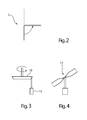
- FIG. 2 schematically illustrates an X-ray optical element which is structured to rotate about an axis of a beam propagation direction
- FIG. 3 illustrates a point source having a rotating anode and a microfocus source
- FIG. 4 shows a point source having a liquid metal configuration
- FIG. 5 shows a collimator disposed proximate to the sample
- FIG. 6 illustrates a monochromator disposed between the X-ray optical element and the sample.
- FIG. 1 schematically shows the inventive device.
- the illustration shows a sectional view in the longitudinal direction through the inventive device.
- the sample 1 is irradiated by X-ray radiation which propagates from the X-ray source 2 through the inventive X-ray optical element 3 .
- the X-ray source 2 comprises a brilliant point source 4 .
- FIGS. 2 through 6 illustrate certain embodiments of the invention.
- the reference symbols correspond to those used in FIG. 1 .
- FIGS. 5 and 6 correspond to FIG. 1 but with additional structural elements.
- FIG. 2 schematically illustrates an X-ray optical element 3 which is structured to rotate about an axis of a beam propagation direction through an angle of approximately 90 degrees.
- the beam is directed perpendicular to the plane of the drawing.
- the 90 degree rotation is schematically indicated by the presence of an arrow such that the X-ray optical element 3 can rotate from the position indicated by the solid lines into that indicated by the dashed lines in the figure.
- the point source 4 can comprise an anode 10 and a microfocus source 12 .
- the anode 10 is structured to rotate, as is schematically indicated by the arrow in FIG. 3 .
- the point source 4 can comprise a liquid metal configuration 14 .
- a collimator 16 can be disposed in an area of the sample 1 for collimating down the X-ray beam from a line shape cross section profile to a beam profile having essentially a point shaped cross section.
- a monochromator 18 can be disposed between the x-ray optical element 3 and the sample 1 .
Landscapes
- Physics & Mathematics (AREA)
- Spectroscopy & Molecular Physics (AREA)
- Engineering & Computer Science (AREA)
- General Engineering & Computer Science (AREA)
- High Energy & Nuclear Physics (AREA)
- Analysing Materials By The Use Of Radiation (AREA)
Abstract
Description
- 1 sample
- 2 X-ray source
- 3 X-ray optical element
- 4 brilliant point source
Claims (12)
Applications Claiming Priority (3)
| Application Number | Priority Date | Filing Date | Title |
|---|---|---|---|
| DE201010062472 DE102010062472A1 (en) | 2010-12-06 | 2010-12-06 | Dot-dash Converter |
| DE102010062472.1 | 2010-12-06 | ||
| DE102010062472 | 2010-12-06 |
Publications (2)
| Publication Number | Publication Date |
|---|---|
| US20120140897A1 US20120140897A1 (en) | 2012-06-07 |
| US8848870B2 true US8848870B2 (en) | 2014-09-30 |
Family
ID=45044441
Family Applications (1)
| Application Number | Title | Priority Date | Filing Date |
|---|---|---|---|
| US13/373,644 Active 2032-12-18 US8848870B2 (en) | 2010-12-06 | 2011-11-23 | Point-line converter |
Country Status (3)
| Country | Link |
|---|---|
| US (1) | US8848870B2 (en) |
| EP (1) | EP2461332B1 (en) |
| DE (1) | DE102010062472A1 (en) |
Families Citing this family (3)
| Publication number | Priority date | Publication date | Assignee | Title |
|---|---|---|---|---|
| WO2013185000A1 (en) | 2012-06-08 | 2013-12-12 | Rigaku Innovative Technologies, Inc. | X-ray beam system offering 1d and 2d beams |
| JP6322627B2 (en) | 2012-06-08 | 2018-05-09 | リガク イノベイティブ テクノロジーズ インコーポレイテッド | Dual mode small angle scattering camera |
| US10352881B2 (en) * | 2016-12-27 | 2019-07-16 | Malvern Panalytical B.V. | Computed tomography |
Citations (10)
| Publication number | Priority date | Publication date | Assignee | Title |
|---|---|---|---|---|
| US6226349B1 (en) | 1998-07-25 | 2001-05-01 | Bruker Axs Analytical X-Ray Systems Gmbh | X-ray analysis apparatus with a graded multilayer mirror |
| US6282259B1 (en) * | 1999-09-10 | 2001-08-28 | Rigaku/Msc, Inc. | X-ray mirror system providing enhanced signal concentration |
| US20030108153A1 (en) | 2001-12-08 | 2003-06-12 | Bruker Axs Gmbh | X-ray optical system and method for imaging a source |
| US20030112923A1 (en) | 2001-12-18 | 2003-06-19 | Bruker Axs Gmbh | X-ray optical system with collimator in the focus of an X-ray mirror |
| US20040019081A1 (en) | 1999-07-30 | 2004-01-29 | Crooks Peter A. | 2, 6-disubstituted piperidines as modulators of nicotinic acetylcholine receptor mediated neurotransmitter release, uptake and storage |
| US20040066894A1 (en) | 2001-02-14 | 2004-04-08 | Thomas Holz | Device for x-ray analytical applications |
| US20040136102A1 (en) | 2003-01-15 | 2004-07-15 | Sang Jin Cho | Apparatus for generating parallel beam with high flux |
| US20040228440A1 (en) | 2003-05-14 | 2004-11-18 | Bruker Axs Gmbh | X-ray diffractometer for high flux grazing incidence diffraction |
| US20070236815A1 (en) | 2006-04-05 | 2007-10-11 | Incoatec Gmbh | Method and device for aligning an optical element |
| US20100086104A1 (en) | 2008-10-08 | 2010-04-08 | Incoatec Gmbh | X-ray analysis instrument with adjustable aperture window |
Family Cites Families (1)
| Publication number | Priority date | Publication date | Assignee | Title |
|---|---|---|---|---|
| JP3697246B2 (en) * | 2003-03-26 | 2005-09-21 | 株式会社リガク | X-ray diffractometer |
-
2010
- 2010-12-06 DE DE201010062472 patent/DE102010062472A1/en not_active Ceased
-
2011
- 2011-11-23 US US13/373,644 patent/US8848870B2/en active Active
- 2011-11-30 EP EP11191307.5A patent/EP2461332B1/en active Active
Patent Citations (10)
| Publication number | Priority date | Publication date | Assignee | Title |
|---|---|---|---|---|
| US6226349B1 (en) | 1998-07-25 | 2001-05-01 | Bruker Axs Analytical X-Ray Systems Gmbh | X-ray analysis apparatus with a graded multilayer mirror |
| US20040019081A1 (en) | 1999-07-30 | 2004-01-29 | Crooks Peter A. | 2, 6-disubstituted piperidines as modulators of nicotinic acetylcholine receptor mediated neurotransmitter release, uptake and storage |
| US6282259B1 (en) * | 1999-09-10 | 2001-08-28 | Rigaku/Msc, Inc. | X-ray mirror system providing enhanced signal concentration |
| US20040066894A1 (en) | 2001-02-14 | 2004-04-08 | Thomas Holz | Device for x-ray analytical applications |
| US20030108153A1 (en) | 2001-12-08 | 2003-06-12 | Bruker Axs Gmbh | X-ray optical system and method for imaging a source |
| US20030112923A1 (en) | 2001-12-18 | 2003-06-19 | Bruker Axs Gmbh | X-ray optical system with collimator in the focus of an X-ray mirror |
| US20040136102A1 (en) | 2003-01-15 | 2004-07-15 | Sang Jin Cho | Apparatus for generating parallel beam with high flux |
| US20040228440A1 (en) | 2003-05-14 | 2004-11-18 | Bruker Axs Gmbh | X-ray diffractometer for high flux grazing incidence diffraction |
| US20070236815A1 (en) | 2006-04-05 | 2007-10-11 | Incoatec Gmbh | Method and device for aligning an optical element |
| US20100086104A1 (en) | 2008-10-08 | 2010-04-08 | Incoatec Gmbh | X-ray analysis instrument with adjustable aperture window |
Non-Patent Citations (2)
| Title |
|---|
| "Super Speed Solutions" Company leaflet, Bruker AXS, Karlsruhe, (2003). |
| Schuster, M. et al., "Parallel-Beam coupling into channel-cut monochromators using curved graded multilayers", Journal of Physics D. Applied Physics, 10P Publishing, Bristol, GB, vol. 28, No. 4A, Apr. 14, 1995, pa. A270-A275. |
Also Published As
| Publication number | Publication date |
|---|---|
| US20120140897A1 (en) | 2012-06-07 |
| DE102010062472A1 (en) | 2012-06-06 |
| EP2461332B1 (en) | 2016-07-27 |
| EP2461332A1 (en) | 2012-06-06 |
Similar Documents
| Publication | Publication Date | Title |
|---|---|---|
| US7551722B2 (en) | X-ray target and apparatuses using the same | |
| Reichert et al. | A new X-ray transmission-reflection scheme for the study of deeply buried interfaces using high-energy microbeams | |
| US9823203B2 (en) | X-ray surface analysis and measurement apparatus | |
| US9594036B2 (en) | X-ray surface analysis and measurement apparatus | |
| Stampanoni et al. | TOMCAT: A beamline for TOmographic Microscopy and Coherent rAdiology experimenTs | |
| Avila et al. | ANTARES, a scanning photoemission microscopy beamline at SOLEIL | |
| Peetermans et al. | Cold neutron diffraction contrast tomography of polycrystalline material | |
| Etzelstorfer et al. | Scanning X-ray strain microscopy of inhomogeneously strained Ge micro-bridges | |
| CN109991253A (en) | A capillary focused microbeam X-ray diffractometer | |
| Falkenberg et al. | Upgrade of the x‐ray fluorescence beamline at HASYLAB/DESY | |
| US8848870B2 (en) | Point-line converter | |
| Lin et al. | Characterization and applications of a new tabletop confocal micro X-ray fluorescence setup | |
| Perez et al. | Latest developments and opportunities for 3D analysis of biological samples by confocal μ-XRF | |
| Lengeler et al. | Beryllium parabolic refractive x‐ray lenses | |
| US20040066894A1 (en) | Device for x-ray analytical applications | |
| Lynch et al. | A laboratory based system for Laue micro x-ray diffraction | |
| Grigoriev et al. | Two-dimensional X-ray focusing by off-axis grazing incidence phase Fresnel zone plate on the laboratory X-ray source | |
| Bjeoumikhov et al. | A new method of depth sensitive micro-X-ray fluorescence analysis | |
| Rivers et al. | X-ray fluorescence microscopy | |
| Schroer et al. | Compound refractive lenses: high-quality imaging optics for the X-FEL | |
| Fujiwara et al. | Soft X-ray angle-resolved photoemission with micro-positioning techniques for metallic V2O3 | |
| Tajiri et al. | Surface X-ray diffraction in transmission geometry | |
| Li et al. | Focal construct geometry for high intensity energy dispersive x-ray diffraction based on x-ray capillary optics | |
| Vis et al. | On the development of X-ray microprobes using synchrotron radiation | |
| Welzel et al. | Laboratory Instrumentation for X‐Ray Powder Diffraction: Developments and Examples |
Legal Events
| Date | Code | Title | Description |
|---|---|---|---|
| AS | Assignment |
Owner name: BRUKER AXS GMBH, GERMANY Free format text: ASSIGNMENT OF ASSIGNORS INTEREST;ASSIGNORS:BRUEGEMANN, LUTZ;MICHAELSEN, CARSTEN;SAITO, KEISUKE;SIGNING DATES FROM 20111026 TO 20111115;REEL/FRAME:027465/0407 |
|
| STCF | Information on status: patent grant |
Free format text: PATENTED CASE |
|
| MAFP | Maintenance fee payment |
Free format text: PAYMENT OF MAINTENANCE FEE, 4TH YEAR, LARGE ENTITY (ORIGINAL EVENT CODE: M1551) Year of fee payment: 4 |
|
| MAFP | Maintenance fee payment |
Free format text: PAYMENT OF MAINTENANCE FEE, 8TH YEAR, LARGE ENTITY (ORIGINAL EVENT CODE: M1552); ENTITY STATUS OF PATENT OWNER: LARGE ENTITY Year of fee payment: 8 |
|
| AS | Assignment |
Owner name: BRUKER AXS SE, GERMANY Free format text: ASSIGNMENT OF ASSIGNORS INTEREST;ASSIGNOR:BRUKER AXS GMBH;REEL/FRAME:071437/0901 Effective date: 20250612 |
|
| MAFP | Maintenance fee payment |
Free format text: PAYMENT OF MAINTENANCE FEE, 12TH YEAR, LARGE ENTITY (ORIGINAL EVENT CODE: M1553); ENTITY STATUS OF PATENT OWNER: LARGE ENTITY Year of fee payment: 12 |