US8848754B2 - Multiquantum well structures for suppression of electron leakage and reduction of threshold-current density in quantum cascade lasers - Google Patents
Multiquantum well structures for suppression of electron leakage and reduction of threshold-current density in quantum cascade lasers Download PDFInfo
- Publication number
- US8848754B2 US8848754B2 US13/591,645 US201213591645A US8848754B2 US 8848754 B2 US8848754 B2 US 8848754B2 US 201213591645 A US201213591645 A US 201213591645A US 8848754 B2 US8848754 B2 US 8848754B2
- Authority
- US
- United States
- Prior art keywords
- barrier
- energy
- adjacent
- semiconductor structure
- active region
- Prior art date
- Legal status (The legal status is an assumption and is not a legal conclusion. Google has not performed a legal analysis and makes no representation as to the accuracy of the status listed.)
- Active, expires
Links
Images


Classifications
-
- H—ELECTRICITY
- H01—ELECTRIC ELEMENTS
- H01S—DEVICES USING THE PROCESS OF LIGHT AMPLIFICATION BY STIMULATED EMISSION OF RADIATION [LASER] TO AMPLIFY OR GENERATE LIGHT; DEVICES USING STIMULATED EMISSION OF ELECTROMAGNETIC RADIATION IN WAVE RANGES OTHER THAN OPTICAL
- H01S5/00—Semiconductor lasers
- H01S5/20—Structure or shape of the semiconductor body to guide the optical wave ; Confining structures perpendicular to the optical axis, e.g. index or gain guiding, stripe geometry, broad area lasers, gain tailoring, transverse or lateral reflectors, special cladding structures, MQW barrier reflection layers
- H01S5/2004—Confining in the direction perpendicular to the layer structure
- H01S5/2009—Confining in the direction perpendicular to the layer structure by using electron barrier layers
- H01S5/2013—MQW barrier reflection layers
-
- H—ELECTRICITY
- H01—ELECTRIC ELEMENTS
- H01S—DEVICES USING THE PROCESS OF LIGHT AMPLIFICATION BY STIMULATED EMISSION OF RADIATION [LASER] TO AMPLIFY OR GENERATE LIGHT; DEVICES USING STIMULATED EMISSION OF ELECTROMAGNETIC RADIATION IN WAVE RANGES OTHER THAN OPTICAL
- H01S5/00—Semiconductor lasers
- H01S5/30—Structure or shape of the active region; Materials used for the active region
- H01S5/34—Structure or shape of the active region; Materials used for the active region comprising quantum well or superlattice structures, e.g. single quantum well [SQW] lasers, multiple quantum well [MQW] lasers or graded index separate confinement heterostructure [GRINSCH] lasers
- H01S5/3401—Structure or shape of the active region; Materials used for the active region comprising quantum well or superlattice structures, e.g. single quantum well [SQW] lasers, multiple quantum well [MQW] lasers or graded index separate confinement heterostructure [GRINSCH] lasers having no PN junction, e.g. unipolar lasers, intersubband lasers, quantum cascade lasers
-
- B—PERFORMING OPERATIONS; TRANSPORTING
- B82—NANOTECHNOLOGY
- B82Y—SPECIFIC USES OR APPLICATIONS OF NANOSTRUCTURES; MEASUREMENT OR ANALYSIS OF NANOSTRUCTURES; MANUFACTURE OR TREATMENT OF NANOSTRUCTURES
- B82Y20/00—Nanooptics, e.g. quantum optics or photonic crystals
-
- H—ELECTRICITY
- H01—ELECTRIC ELEMENTS
- H01S—DEVICES USING THE PROCESS OF LIGHT AMPLIFICATION BY STIMULATED EMISSION OF RADIATION [LASER] TO AMPLIFY OR GENERATE LIGHT; DEVICES USING STIMULATED EMISSION OF ELECTROMAGNETIC RADIATION IN WAVE RANGES OTHER THAN OPTICAL
- H01S5/00—Semiconductor lasers
- H01S5/30—Structure or shape of the active region; Materials used for the active region
- H01S5/34—Structure or shape of the active region; Materials used for the active region comprising quantum well or superlattice structures, e.g. single quantum well [SQW] lasers, multiple quantum well [MQW] lasers or graded index separate confinement heterostructure [GRINSCH] lasers
- H01S5/3401—Structure or shape of the active region; Materials used for the active region comprising quantum well or superlattice structures, e.g. single quantum well [SQW] lasers, multiple quantum well [MQW] lasers or graded index separate confinement heterostructure [GRINSCH] lasers having no PN junction, e.g. unipolar lasers, intersubband lasers, quantum cascade lasers
- H01S5/3402—Structure or shape of the active region; Materials used for the active region comprising quantum well or superlattice structures, e.g. single quantum well [SQW] lasers, multiple quantum well [MQW] lasers or graded index separate confinement heterostructure [GRINSCH] lasers having no PN junction, e.g. unipolar lasers, intersubband lasers, quantum cascade lasers intersubband lasers, e.g. transitions within the conduction or valence bands
-
- H—ELECTRICITY
- H01—ELECTRIC ELEMENTS
- H01S—DEVICES USING THE PROCESS OF LIGHT AMPLIFICATION BY STIMULATED EMISSION OF RADIATION [LASER] TO AMPLIFY OR GENERATE LIGHT; DEVICES USING STIMULATED EMISSION OF ELECTROMAGNETIC RADIATION IN WAVE RANGES OTHER THAN OPTICAL
- H01S5/00—Semiconductor lasers
- H01S5/20—Structure or shape of the semiconductor body to guide the optical wave ; Confining structures perpendicular to the optical axis, e.g. index or gain guiding, stripe geometry, broad area lasers, gain tailoring, transverse or lateral reflectors, special cladding structures, MQW barrier reflection layers
-
- H—ELECTRICITY
- H01—ELECTRIC ELEMENTS
- H01S—DEVICES USING THE PROCESS OF LIGHT AMPLIFICATION BY STIMULATED EMISSION OF RADIATION [LASER] TO AMPLIFY OR GENERATE LIGHT; DEVICES USING STIMULATED EMISSION OF ELECTROMAGNETIC RADIATION IN WAVE RANGES OTHER THAN OPTICAL
- H01S5/00—Semiconductor lasers
- H01S5/30—Structure or shape of the active region; Materials used for the active region
- H01S5/32—Structure or shape of the active region; Materials used for the active region comprising PN junctions, e.g. hetero- or double- heterostructures
- H01S5/3211—Structure or shape of the active region; Materials used for the active region comprising PN junctions, e.g. hetero- or double- heterostructures characterised by special cladding layers, e.g. details on band-discontinuities
- H01S5/3216—Structure or shape of the active region; Materials used for the active region comprising PN junctions, e.g. hetero- or double- heterostructures characterised by special cladding layers, e.g. details on band-discontinuities quantum well or superlattice cladding layers
-
- H—ELECTRICITY
- H01—ELECTRIC ELEMENTS
- H01S—DEVICES USING THE PROCESS OF LIGHT AMPLIFICATION BY STIMULATED EMISSION OF RADIATION [LASER] TO AMPLIFY OR GENERATE LIGHT; DEVICES USING STIMULATED EMISSION OF ELECTROMAGNETIC RADIATION IN WAVE RANGES OTHER THAN OPTICAL
- H01S5/00—Semiconductor lasers
- H01S5/30—Structure or shape of the active region; Materials used for the active region
- H01S5/34—Structure or shape of the active region; Materials used for the active region comprising quantum well or superlattice structures, e.g. single quantum well [SQW] lasers, multiple quantum well [MQW] lasers or graded index separate confinement heterostructure [GRINSCH] lasers
- H01S5/3407—Structure or shape of the active region; Materials used for the active region comprising quantum well or superlattice structures, e.g. single quantum well [SQW] lasers, multiple quantum well [MQW] lasers or graded index separate confinement heterostructure [GRINSCH] lasers characterised by special barrier layers
-
- H—ELECTRICITY
- H01—ELECTRIC ELEMENTS
- H01S—DEVICES USING THE PROCESS OF LIGHT AMPLIFICATION BY STIMULATED EMISSION OF RADIATION [LASER] TO AMPLIFY OR GENERATE LIGHT; DEVICES USING STIMULATED EMISSION OF ELECTROMAGNETIC RADIATION IN WAVE RANGES OTHER THAN OPTICAL
- H01S5/00—Semiconductor lasers
- H01S5/30—Structure or shape of the active region; Materials used for the active region
- H01S5/34—Structure or shape of the active region; Materials used for the active region comprising quantum well or superlattice structures, e.g. single quantum well [SQW] lasers, multiple quantum well [MQW] lasers or graded index separate confinement heterostructure [GRINSCH] lasers
- H01S5/341—Structures having reduced dimensionality, e.g. quantum wires
- H01S5/3412—Structures having reduced dimensionality, e.g. quantum wires quantum box or quantum dash
-
- H—ELECTRICITY
- H01—ELECTRIC ELEMENTS
- H01S—DEVICES USING THE PROCESS OF LIGHT AMPLIFICATION BY STIMULATED EMISSION OF RADIATION [LASER] TO AMPLIFY OR GENERATE LIGHT; DEVICES USING STIMULATED EMISSION OF ELECTROMAGNETIC RADIATION IN WAVE RANGES OTHER THAN OPTICAL
- H01S5/00—Semiconductor lasers
- H01S5/30—Structure or shape of the active region; Materials used for the active region
- H01S5/34—Structure or shape of the active region; Materials used for the active region comprising quantum well or superlattice structures, e.g. single quantum well [SQW] lasers, multiple quantum well [MQW] lasers or graded index separate confinement heterostructure [GRINSCH] lasers
- H01S5/3413—Structure or shape of the active region; Materials used for the active region comprising quantum well or superlattice structures, e.g. single quantum well [SQW] lasers, multiple quantum well [MQW] lasers or graded index separate confinement heterostructure [GRINSCH] lasers comprising partially disordered wells or barriers
-
- H—ELECTRICITY
- H01—ELECTRIC ELEMENTS
- H01S—DEVICES USING THE PROCESS OF LIGHT AMPLIFICATION BY STIMULATED EMISSION OF RADIATION [LASER] TO AMPLIFY OR GENERATE LIGHT; DEVICES USING STIMULATED EMISSION OF ELECTROMAGNETIC RADIATION IN WAVE RANGES OTHER THAN OPTICAL
- H01S5/00—Semiconductor lasers
- H01S5/30—Structure or shape of the active region; Materials used for the active region
- H01S5/34—Structure or shape of the active region; Materials used for the active region comprising quantum well or superlattice structures, e.g. single quantum well [SQW] lasers, multiple quantum well [MQW] lasers or graded index separate confinement heterostructure [GRINSCH] lasers
- H01S5/3418—Structure or shape of the active region; Materials used for the active region comprising quantum well or superlattice structures, e.g. single quantum well [SQW] lasers, multiple quantum well [MQW] lasers or graded index separate confinement heterostructure [GRINSCH] lasers using transitions from higher quantum levels
-
- H—ELECTRICITY
- H01—ELECTRIC ELEMENTS
- H01S—DEVICES USING THE PROCESS OF LIGHT AMPLIFICATION BY STIMULATED EMISSION OF RADIATION [LASER] TO AMPLIFY OR GENERATE LIGHT; DEVICES USING STIMULATED EMISSION OF ELECTROMAGNETIC RADIATION IN WAVE RANGES OTHER THAN OPTICAL
- H01S5/00—Semiconductor lasers
- H01S5/30—Structure or shape of the active region; Materials used for the active region
- H01S5/34—Structure or shape of the active region; Materials used for the active region comprising quantum well or superlattice structures, e.g. single quantum well [SQW] lasers, multiple quantum well [MQW] lasers or graded index separate confinement heterostructure [GRINSCH] lasers
- H01S5/3425—Structure or shape of the active region; Materials used for the active region comprising quantum well or superlattice structures, e.g. single quantum well [SQW] lasers, multiple quantum well [MQW] lasers or graded index separate confinement heterostructure [GRINSCH] lasers comprising couples wells or superlattices
Definitions
- Quantum cascade lasers are made of stages each of which is composed of three regions: an electron injector, an active region and an electron extractor.
- the quantum wells and barriers in all regions are of the same, fixed alloy composition, respectively.
- the electrons in the injector and upper laser level are found to have a higher temperature than that of the lattice—that is, they are hot.
- CW continuous wave
- Semiconductor structures and laser devices including the semiconductor structures are provided.
- a semiconductor structure comprises an electron injector, an active region adjacent to the electron injector, and an electron extractor adjacent to the active region.
- the electron injector, active region, and electron extractor each comprise layers of semiconductor, the layers configured to provide alternating quantum wells and barriers.
- the active region comprises an injection barrier, an exit barrier and a multiquantum well structure between the injection barrier and the exit barrier.
- the multiquantum well structure comprises a first barrier, a first quantum well adjacent to the first barrier, a second barrier adjacent to the first quantum well, a second quantum well adjacent to the second barrier, and a third barrier adjacent to the second quantum well.
- the energies of the first barrier and the second barrier are less than the energy of the third barrier, the energy difference between the energy of the second barrier and the energy of the third barrier is greater than 225 meV and the ratio of the energy of the third barrier to the energy of the second barrier is greater than 1.26.
- a semiconductor structure comprises an electron injector, an active region adjacent to the electron injector, and an electron extractor adjacent to the active region.
- the electron injector, active region, and electron extractor each comprise layers of semiconductor, the layers configured to provide alternating quantum wells and barriers.
- the active region comprises an injection barrier, an exit barrier and a multiquantum well structure between the injection barrier and the exit barrier.
- the multiquantum well structure comprises a first barrier, a first quantum well adjacent to the first barrier, a second barrier adjacent to the first quantum well, a second quantum well adjacent to the second barrier, and a third barrier adjacent to the second quantum well.
- the energies of the first barrier and the second barrier are less than the energy of the third barrier, the energy difference between the energy of the second barrier and the energy of the third barrier is greater than 150 meV and the ratio of the energy of the third barrier to the energy of the second barrier is greater than 1.26.
- the semiconductor structure is configured to provide a laser device emitting at a wavelength greater than about 5 ⁇ m.
- a semiconductor structure comprises an electron injector, an active region adjacent to the electron injector, and an electron extractor adjacent to the active region.
- the electron injector, active region, and electron extractor each comprise layers of semiconductor, the layers configured to provide alternating quantum wells and barriers.
- the active region comprises an injection barrier, an exit barrier and a multiquantum well structure between the injection barrier and the exit barrier.
- the multiquantum well structure comprises a first barrier, a first quantum well adjacent to the first barrier, a second barrier adjacent to the first quantum well, a second quantum well adjacent to the second barrier, and a third barrier adjacent to the second quantum well.
- the energies of the first barrier and the second barrier are less than the energy of the third barrier, the energy of at least one of the first barrier and the second barrier is equal to or less than the energy of the barriers of the electron injector, and the energy of the third barrier is greater than the energy of the barriers of the electron injector.
- a semiconductor structure comprises an electron injector, an active region adjacent to the electron injector, and an electron extractor adjacent to the active region.
- the electron injector, active region, and electron extractor each comprise layers of semiconductor, the layers configured to provide alternating quantum wells and barriers.
- the active region comprises an injection barrier, an exit barrier and a multiquantum well structure between the injection barrier and the exit barrier.
- the multiquantum well structure comprises a first barrier, a first quantum well adjacent to the first barrier, a second barrier adjacent to the first quantum well, and a second quantum well adjacent to the second barrier.
- the energies of the first barrier and the second barrier are less than the energy of the exit barrier, the energy difference between the energy of the second barrier and the energy of the exit barrier is greater than 225 meV and the ratio of the energy of the exit barrier to the energy of the second barrier is greater than 1.26.
- FIG. 1 shows the band diagram and relevant wavefunctions for a conventional QCL.
- FIG. 2A shows the band diagram and relevant wavefunctions for an exemplary embodiment of the disclosed semiconductor structures.
- the structure is configured to provide a laser device emitting radiation at a wavelength of 4.0 ⁇ m.
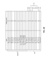
- FIG. 2B shows the compositions and thicknesses of each of the quantum wells and barriers in the semiconductor structure of FIG. 2A .
- FIG. 3A shows the band diagram and relevant wavefunctions for an exemplary embodiment of the disclosed semiconductor structures.
- the structure is configured to provide a laser device emitting radiation at a wavelength of 4.7 ⁇ m.
- FIG. 3B shows the compositions and thicknesses of each of the quantum wells and barriers in the semiconductor structure of FIG. 3A .
- FIG. 4A shows the band diagram and relevant wavefunctions for an exemplary embodiment of the disclosed semiconductor structures.
- the structure is configured to provide a laser device emitting radiation at a wavelength of 8.0 ⁇ m.
- FIG. 4B shows the compositions and thicknesses of each of the quantum wells and barriers in the semiconductor structure of FIG. 4A .
- semiconductor structures and laser devices including the semiconductor structures are provided. At least some embodiments of the semiconductor structures are capable of providing laser devices emitting mid- to long-wavelength infrared radiation (i.e., 3-16 ⁇ m) and operating at high power (i.e., watt-range) and high wallplug efficiency during quasi-continuous wave or continuous wave (CW) operation over long periods of time (i.e., >1000 hours). Such laser devices are suited for use in a variety of applications, ranging from environmental monitoring to remote detection of explosives and to missile-avoidance systems for both commercial and military air vehicles.
- the present invention is based, at least in part, on the inventors' findings that electron leakage can be virtually suppressed and threshold-current density, J th , can be significantly reduced (beyond that provided via the suppression of electron leakage) by using certain multiquantum well structures in the active regions of QCL devices.
- J th threshold-current density
- laser devices including at least some embodiments of the disclosed semiconductor structures exhibit superior electro-optical characteristics as compared to conventional and other QCLs.
- the combination of very low J th values and virtually suppressed electron leakage leads to significantly higher pulsed or continuous wave (CW) wallplug efficiencies at room temperature.
- CW continuous wave
- FIG. 1 shows the band diagram and relevant wavefunctions for a conventional QCL emitting at 4.7 ⁇ m.
- One stage 100 of the QCL includes an injector region 102 , an active region 104 , and an extractor region 106 .
- the barriers of the active region include an injection barrier 108 , an exit barrier 110 , and intermediate barriers 112 .
- Electrons are injected from the ground level, g, in the injector region into the upper laser state 4 in the active region. Some electrons relax down to the lower laser state 3, with light being emitted at the desired wavelength.
- the primary electron leakage mechanism is thermal excitation from the upper laser state 4, to the next higher energy level in the active region, state 5, followed by relaxation to all lower active region energy levels.
- FIG. 1 shows the band diagram and relevant wavefunctions for a conventional QCL emitting at 4.7 ⁇ m.
- One stage 100 of the QCL includes an injector region 102 , an active region 104 , and an extractor region 106 .
- ⁇ 54 is 0.25 ps.
- ⁇ up,g ⁇ 4g (1 ⁇ 3g / ⁇ 43 ), where ⁇ 4g and ⁇ 3g are the global electron lifetimes of states 4 and 3, respectively, corresponding to transitions to all lower active region states [i.e., to states 3, 2, 1 (for state 4) and to extractor states penetrating into the active region].
- ⁇ up,g is 1.235 ps.
- the present invention is based, at least in part, on the inventors' findings that multiquantum well structures having certain configurations of quantum wells and barriers can greatly suppress electron leakage and decrease threshold-current density when incorporated into the active regions of QCLs.
- the multiquantum well structures provide laser devices exhibiting very high values of E 54 and ⁇ 54 , but also, they provide laser devices exhibiting very high values of ⁇ up,g .
- J leak is significantly decreased (from high values of E 54 and ⁇ 54 ) and J th is further decreased (from high values of ⁇ up,g ).
- the inventors have found that the first-order Stark effect can be minimized by use of certain configurations of the quantum wells and barriers in the multiquantum well structures, which, at least in part, allows these high values of E 54 to be realized. See D. Botez et al., “Tapered active-region, mid-infrared quantum cascade lasers for complete suppression of carrier-leakage currents,” Proc. SPIE 8277, 82770W (2012), which is hereby incorporated by reference in its entirety.
- Semiconductor structures comprise an electron injector, an active region adjacent to the electron injector, and an electron extractor adjacent to the active region.
- the electron injector, active region, and electron extractor each comprise layers of semiconductor, the layers configured to provide alternating quantum wells and barriers.
- the active region comprises an injection barrier, an exit barrier and a multiquantum well structure between the injection barrier and the exit barrier.
- the multiquantum well structure comprises a first barrier, a first quantum well adjacent to the first barrier, a second barrier adjacent to the first quantum well, a second quantum well adjacent to the second barrier, and a third barrier adjacent to the second quantum well. The energies of the first barrier and the second barrier are less than the energy of the third barrier.
- the first quantum well may be downstream from the first barrier; the second barrier may be downstream from the first quantum well; the second quantum well may be downstream from the second barrier; and the third barrier may be downstream from the second quantum well.
- the direction “downstream” is the same direction as the direction of the electron flow in a QCL device incorporating the disclosed semiconductor structures.
- the energies of the first barrier and the second barrier may assume a range of values (i.e., less than, equal to, or greater than) relative to the energy of the barriers of the electron injector. However, in some embodiments, the energy of at least one of the first barrier and the second barrier is less than or equal to the energy of the barriers of the electron injector. In some embodiments, the energy of the first barrier is less than or equal to the energy of the barriers of the electron injector. In some embodiments, the energy of the second barrier is less than or equal to the energy of the barriers of the electron injector. In some embodiments, the energies of both the first barrier and the second barrier are less than or equal to the energy of the barriers of the electron injector.
- the energy of at least one of the first barrier and the second barrier is greater than the energy of the barriers of the electron injector. In some embodiments, the energy of the first barrier is greater than the energy of the barriers of the electron injector. In some embodiments, the energy of the second barrier is greater than the energy of the barriers of the electron injector. In some embodiments, the energies of both the first barrier and the second barrier are greater than the energy of the barriers of the electron injector.
- the energies of the first barrier and the second barrier may assume a range of values (i.e., less than, equal to, or greater than) relative to the energy of the injection barrier. However, in some embodiments, the energies of both the first barrier and the second barrier are less than the energy of the injection barrier. In some embodiments, the energies of both the first barrier and the second barrier are equal to or greater than the energy of the injection barrier. In some embodiments, the energy of the first barrier is equal to or less than the energy of the injection barrier and the energy of the second barrier is greater than the energy of the injection barrier.
- the energies of the first barrier and the second barrier may assume a range of values (i.e., less than, equal to, or greater than) relative to the energy of the exit barrier. However, in some embodiments, the energies of both the first barrier and the second barrier are less than the energy of the exit barrier.
- the energies of the first barrier and the second barrier may assume a range of values relative to each other. However, in some embodiments, the energy of the first barrier is less than the energy of the second barrier. In some embodiments, the energy of the first barrier is greater than the energy of the second barrier. In some embodiments, the energies of the first barrier and the second barrier are the same. In some embodiments, the energies of the first barrier and the second barrier are substantially the same. By “substantially” it is meant that the energy difference between the energy of the first barrier and the energy of the second barrier is 10 meV or less. This includes embodiments in which the energy difference is 8 meV or less, 6 meV or less, 4 meV or less, 2 meV or less, or 1 meV or less.
- the energy of the third barrier may assume a range of values (i.e., less than, equal to, or greater than) relative to the energy of the barriers of the electron injector. However, in some embodiments, the energy of the third barrier is greater than the energy of the barriers of the electron injector.
- the energy of the third barrier may assume a range of values (i.e., less than, equal to, or greater than) relative to the energy of the injection barrier. However, in some embodiments, the energy of the third barrier is greater than the energy of the injection barrier.
- the energy of the third barrier may assume a range of values (i.e., less than, equal to, or greater than) relative to the energy of the exit barrier. However, in some embodiments, the energy of the third barrier is greater than the energy of the exit barrier. In some embodiments, the energies of the third barrier and the exit barrier are the same. In some embodiments, the energies of the third barrier and the exit barrier are substantially the same. By “substantially” it is meant that the energy difference between the energy of the third barrier and the energy of the exit barrier is 10 meV or less. This includes embodiments in which the energy difference is 8 meV or less, 6 meV or less, 4 meV or less, 2 meV or less, or 1 meV or less.
- the energies of the first barrier and the second barrier are less than the energy of the third barrier.
- the difference in energy between the energy of the second barrier and the energy of the third barrier is greater than 150 meV.
- the difference in energy between the energy of the second barrier and the energy of the third barrier is greater than 175 meV, greater than 180 meV, greater than 200 meV, greater than 225 meV, greater than 250 meV, greater than 275 meV, greater than 300 meV, greater than 325 meV, greater than 350 meV, greater than 375 meV, or greater than 400 meV.
- the ratio of the energy of the third barrier to the energy of the second barrier is greater than 1.20. This includes embodiments in which the ratio of energy of the third barrier to the energy of the second barrier is greater than 1.22, greater than 1.24, greater than 1.26, greater than 1.28, greater than 1.30, greater than 1.32, greater than 1.34, greater than 1.36, greater than 1.38, greater than 1.40, greater than 1.42, greater than 1.44, greater than 1.46, greater than 1.48, or greater than 1.50.
- the difference in energy between the energy of the second barrier and the energy of the third barrier is within any of the ranges disclosed above and the ratio of the energy of the third barrier to the energy of the second barrier is within any of the ranges disclosed above.
- the difference in energy between the energy of the second barrier and the energy of the third barrier is greater than 225 meV and the ratio of the energy of the third barrier to the energy of the second barrier is greater than 1.26.
- the energy of the injection barrier may assume a range of values (i.e., less than, equal to, or greater than) relative to the energy of the barriers of the electron injector. However, in some embodiments, the energy of the injection barrier is greater than the energy of the barriers of the electron injector. In some embodiments, the energy of the injection barrier is equal to the energy of the barriers of the electron injector. Similarly, the energy of the injection barrier may assume a range of values (i.e., less than, equal to, or greater than) relative to the energy of the exit barrier. However, in some embodiments, the energy of the injection barrier is less than the energy of the exit barrier.
- the energy of the exit barrier may assume a range of values (i.e., less than, equal to, or greater than) relative to the energy of the barriers of the electron injector. However, in some embodiments, the energy of the exit barrier is greater than the energy of the barriers of the electron injector.
- quantum wells and barriers may be included between the injection barrier and the multiquantum well structure and between the multiquantum well structure and the exit barrier.
- a quantum well is between the injection barrier and the multiquantum well structure, such that the first barrier of the multiquantum well structure is adjacent to the quantum well which is adjacent to the injection barrier.
- one or more barriers and associated quantum wells are between the injection barrier and the first barrier of the multiquantum well structure.
- a quantum well is between the multiquantum well structure and the exit barrier, such that the third barrier of the multiquantum well structure is adjacent to the quantum well which is adjacent to the exit barrier.
- one or more barriers and associated quantum wells are between the exit barrier and the third barrier of the multiquantum well structure.
- a single-phonon-resonance multiquantum well structure comprises a first barrier, a first quantum well adjacent to the first barrier, a second barrier adjacent to the first quantum well, and a second quantum well adjacent to the second barrier.
- the energies of the first barrier and the second barrier are less than the energy of the exit barrier.
- the first quantum well may be downstream from the first barrier; the second barrier may be downstream from the first quantum well; and the second quantum well may be downstream from the second barrier.
- the energies of the first barrier and the second barrier may assume the range of values relative to the energy of the barriers of the electron injector as described above.
- the energies of the first barrier and the second barrier may assume the range of values relative to the energy of the injection barrier as described above.
- the energies of the first barrier and the second barrier may assume the range of values relative to each other as described above.
- the energy of the exit barrier may assume the range of values relative to the energy of the barriers of the electron injector and relative to the energy of the injection barrier as described above.
- the energy of the injection barrier may assume the range of values relative to the energy of the barriers of the electron injector as described above.
- the difference in energy between the energy of the second barrier and the energy of the exit barrier is greater than 225 meV. This includes embodiments in which the difference in energy between the energy of the second barrier and the energy of the exit barrier is greater than 250 meV, greater than 275 meV, greater than 300 meV, greater than 325 meV, greater than 350 meV, greater than 375 meV, or greater than 400 meV.
- the ratio of the energy of the exit barrier to the energy of the second barrier is greater than 1.20. This includes embodiments in which the ratio of energy of the exit barrier to the energy of the second barrier is greater than 1.22, greater than 1.24, greater than 1.26, greater than 1.28, greater than 1.30, greater than 1.32, greater than 1.34, greater than 1.36, greater than 1.38, greater than 1.40, greater than 1.42, greater than 1.44, greater than 1.46, greater than 1.48, or greater than 1.50.
- the difference in energy between the energy of the second barrier and the energy of the exit barrier is within any of the ranges disclosed above and the ratio of the energy of the exit barrier to the energy of the second barrier is within any of the ranges disclosed above.
- a quantum well is between the injection barrier and the single-phonon-resonance multiquantum well structure, such that the first barrier of the single-phonon-resonance multiquantum well structure is adjacent to the quantum well which is adjacent to the injection barrier.
- the single-phonon-resonance multiquantum well structure is adjacent to the exit barrier such that the second quantum well of the single-phonon-resonance multiquantum well structure is adjacent to the exit barrier.
- the energy of a barrier in the active region may be defined as the difference in energy between the top of the barrier and the bottom of the adjacent, upstream quantum well (upstream refers to the direction opposite the direction of electron flow in a QCL device incorporating the active region).
- upstream refers to the direction opposite the direction of electron flow in a QCL device incorporating the active region.
- the energy of the exit barrier 110 is the difference in energy between the top of the barrier 110 and the bottom of the adjacent, upstream quantum well 114 .
- the barriers of the active region of the disclosed semiconductor structures may be composite barriers.
- Composite barriers are barriers composed of two or more barrier layers of different semiconductors.
- the energy of a composite barrier may be defined with respect to the quantum well which is adjacent to and upstream of the composite barrier.
- the energy of a composite barrier will be of intermediate value between the energy of the barrier layer or barrier layers of highest energy and the energy value of the barrier layer or barrier layers of lowest energy.
- An exemplary composite barrier 208 is shown in FIG. 2A .
- This composite barrier includes a first barrier layer 210 and a second barrier layer 212 .
- the compositions of the first barrier layer (Al 0.77 In 0.23 As) and second barrier layer (Al 0.84 In 0.16 As) differ.
- the energy of the composite barrier 208 is of intermediate value between the energy of the first barrier layer 210 (the difference in energy between the top of the first barrier layer and the bottom of the adjacent, upstream quantum well 234 ) and the energy of the second barrier layer 212 (the difference in energy between the top of the second barrier layer and the bottom of the adjacent, upstream quantum well 234 ).
- the injection barrier in any of the disclosed semiconductor structures is a composite injection barrier including a first barrier layer and a second barrier layer.
- the quantum wells of the active region of the disclosed semiconductor structures may be deep quantum wells.
- a deep quantum well is a quantum well having a well bottom that is lower in potential energy than the bottoms of the quantum wells in the adjacent and upstream electron injector.
- a deep quantum well will have a well bottom that is lower in potential energy than the well bottoms of the quantum wells in the adjacent injector region regardless of whether or not the semiconductor structure is under the influence of an applied electric field. That is, a deep quantum well will have a well bottom that remains lower in potential energy than the well bottoms of the quantum wells in the adjacent injector region even when the semiconductor structure is unbiased.
- Exemplary deep quantum wells 220 , 224 , 230 are shown in FIG. 2A .
- At least one of the quantum wells in the active region is a deep quantum well.
- the quantum well adjacent to and downstream from the injection barrier is a deep quantum well.
- each of the quantum wells in the multiquantum well structure is a deep quantum well.
- each of the quantum wells in the active region is a deep quantum well.
- the disclosed semiconductor structures may comprise quantum wells and barriers having a variety of compositions.
- the semiconductor structure comprises quantum wells of InGaAs and barriers of AlInAs.
- the semiconductor structure could also comprise barriers of AlAs.
- the semiconductor structure comprises quantum wells of InGaAs and barriers of AlAsSb.
- the semiconductor structure could also comprise barriers of AlAs.
- the semiconductor structure comprises quantum wells of GaAs and barriers of AlGaAs.
- the semiconductor structure comprises quantum wells of InGaAs, quantum wells of GaAs, barriers of AlGaAs, barriers of AlGaAsP, and barriers of GaAsP.
- Quantum wells and barriers may be doped or undoped. Specific, exemplary compositions for quantum wells and barriers are provided in FIGS. 2B , 3 B, and 4 B. It is to be understood that at least some of the compositions above are alloys in which the relative proportions of certain elements may vary. As one example only, InGaAs refers to an alloy of indium, gallium and arsenic in which the relative proportions of indium and gallium may vary.
- the active region of the disclosed semiconductor structures includes upper energy states 4 and 5 (e.g., see the exemplary embodiment shown in FIG. 2A ), wherein the energy difference between energy states 4 and 5 is denoted by E 54 .
- E 54 is at least 90 meV. This includes embodiments in which E 54 is at least 95 meV, at least 98 meV, or at least 100 meV.
- ⁇ 54 is at least 1.0 ps.
- ⁇ 54 is at least about 1.1 ps, at least 1.2 ps, at least 1.3 ps, at least 1.4 ps, or at least 1.5 ps.
- the semiconductor structures are configured to provide a laser device emitting radiation in the wavelength range of 4.5-8.5 ⁇ m.
- at least certain embodiments of the disclosed semiconductor structures provide much higher values of ⁇ up,g , directly contributing to reduced J th .
- ⁇ up,g is at least 1.4 ps. This includes embodiments in which ⁇ up,g is at least 1.5 ps, at least 1.6 ps, at least 1.7 ps, at least 1.8 ps, or at least 2 ps.
- the disclosed semiconductor structures may be configured to provide laser devices emitting in the mid- to long-wavelength infrared range (i.e., 3-16 ⁇ m).
- the semiconductor structure is configured to provide a laser device emitting radiation in the wavelength range from about 3 ⁇ m to about 4 ⁇ m, from about 3 ⁇ m to about 5 ⁇ m, from about 3.5 ⁇ m to about 5 ⁇ m, from about 4 ⁇ m to about 5 ⁇ m, from about 4.5 ⁇ m to about 5 ⁇ m, from greater than about 5 ⁇ m, from greater than about 8 ⁇ m, or from about 8 ⁇ m to about 16 ⁇ m.
- the laser devices including any of the disclosed semiconductor structures.
- Such laser devices include a plurality of laser stages, each laser stage comprising any of the disclosed semiconductor structures.
- the laser devices include at least 10, at least 25, at least 30, or at least 40 laser stages.
- the disclosed semiconductor structures are capable of providing laser devices including the structures with superior electro-optical characteristics, including low electron leakage, low values of J th at room temperature, and high maximum wallplug efficiencies.
- the semiconductor structure is configured to provide a laser device emitting from about 4 ⁇ m to about 5 ⁇ m, wherein the laser device is characterized by a relative leakage-current density value (J leak /J th ) of 5% or less. This includes embodiments in which J leak /J th is 4% or less, 3% or less, 2% or less, or 1% or less.
- the threshold-current density, J th may be calculated as described above, or may be experimentally determined using known methods.
- J leak The electron leakage-current density, J leak , may also be calculated from the appropriate equations found in D. Botez, et al., “Temperature dependence of the key electro-optical characteristics for mid-infrared emitting quantum cascade lasers,” Applied Physics Letters, 97, 071101 (2010) and D. Botez, et al., Erratum: “Temperature dependence of the key electro-optical characteristics for midinfrared emitting quantum cascade lasers” [ Appl. Phys. Lett. 97, 071101 (2010)], Applied Physics Letters, 97, 199901 (2010), each of which is hereby incorporated by reference in its entirety.
- the semiconductor structure is configured to provide a laser device emitting radiation in the wavelength range from about 3.5 to about 4 ⁇ m, wherein the laser device exhibits a room temperature CW maximum wallplug efficiency ( ⁇ wp,max ) greater than 10%. This includes embodiments in which the room temperature CW maximum wallplug efficiency is greater than 11%, greater than 12%, greater than 13%, greater than 14%, or greater than 15%.
- the semiconductor structure is configured to provide a laser device emitting radiation in the wavelength range from about 4 to about 5 ⁇ m, wherein the laser device exhibits a front-facet, room temperature CW maximum wallplug efficiency ( ⁇ wp,max ) greater than 20%.
- ⁇ wp,max value may be calculated from the appropriate equations found in D. Botez, et al., “Temperature dependence of the key electro-optical characteristics for mid-infrared emitting quantum cascade lasers,” Applied Physics Letters, 97, 071101 (2010), which is hereby incorporated by reference in its entirety.
- semiconductor structures may be grown on an appropriate substrate (e.g., InP, GaAs, GaSb, and InAs) using metal-organic chemical vapor deposition (MOCVD).
- MOCVD metal-organic chemical vapor deposition
- Metamorphic buffer layer structures may be used for growth as described in U.S. Ser. No. 13/283,855, which is incorporated by reference in its entirety.
- FIG. 2A shows the band diagram and relevant wavefunctions for a semiconductor structure 200 under an applied field of 82 kV/cm (i.e., under bias).
- the semiconductor structure 200 is configured to provide a laser device emitting radiation at a wavelength of 4.0 ⁇ m.
- FIG. 2B shows the compositions and thicknesses of each of the quantum wells and barriers in the semiconductor structure 200 of FIG. 2A .
- the semiconductor structure is grown on a metamorphic buffer layer structure, which itself is grown on a GaAs substrate.
- the upper layer of the metamorphic buffer layer structure corresponds to an In 0.30 Ga 0.70 As virtual substrate.
- the semiconductor structure 200 includes an electron injector 202 , an active region 204 , and an electron extractor 206 .
- the active region 204 includes an injection barrier 208 , which is a composite injection barrier including a first barrier layer 210 and a second barrier layer 212 .
- the energy of the injection barrier 208 will be determined with respect to the adjacent, upstream quantum well 234 and will have an intermediate value between the energy of the first barrier layer 210 and the energy of the second barrier layer 212 .
- the active region also includes an exit barrier 214 .
- the active region also includes a coupled multiquantum well structure 216 .
- the coupled multiquantum well structure includes a first barrier 218 , a first quantum well 220 , a second barrier 222 , a second quantum well 224 , and a third barrier 226 .
- the energies of the first barrier 218 and the second barrier 222 are less than the energy of the third barrier 226 and less than the energy of the barriers 228 of the electron injector.
- the energy of the first barrier 218 is the same as the energy of the second barrier 222 .
- the difference in energy between the second barrier 222 and the third barrier 226 is 400 meV and the ratio of the energy of the third barrier and the energy of the second barrier is 1.49.
- the energy of the third barrier 226 is greater than the energy of the barriers 228 of the electron injector.
- the energies of the injection barrier 208 and the exit barrier 214 are also greater than the energy of the barriers 228 of the electron injector.
- the energy of the injection barrier 208 is less than the energy of the third barrier 226 and the energy of the exit barrier 214 .
- the energy of the exit barrier 214 is also less than the energy of the third barrier 226 .
- the quantum wells 230 of the active region, including the quantum wells 220 and 224 of the coupled multiquantum well structure, are all deep quantum wells. These layers are also identified in the composition table shown in FIG. 2B .
- FIG. 2A also shows that the E 54 value for the semiconductor structure 200 is 98 meV.
- the value for ⁇ 54 is 0.60 ps.
- the value for ⁇ up,g is 1.27 ps.
- the relative leakage-current density, J leak /J th at room temperature for a laser device including the semiconductor structure 200 is at least 5 times smaller than for a conventional QCL emitting at 4.0 ⁇ m.
- the room temperature CW wallplug efficiency for a laser device including the semiconductor structure 200 is at least two times greater than for a conventional QCL emitting at 4.0 ⁇ m.
- FIG. 3A shows the band diagram and relevant wavefunctions for a semiconductor structure 300 under an applied field of 72 kV/cm (i.e., under bias).
- the semiconductor structure 300 is configured to provide a laser device emitting radiation at a wavelength of 4.7 ⁇ m.
- FIG. 3B shows the compositions and thicknesses of each of the quantum wells and barriers in the semiconductor structure 300 of FIG. 3A .
- the semiconductor structure 300 includes an electron injector 302 , an active region 304 , and an electron extractor 306 .
- the active region 304 includes an injection barrier 308 , which is a composite injection barrier including a first barrier layer 310 and a second barrier layer 312 .
- the energy of the injection barrier 308 will be determined with respect to the adjacent, upstream quantum well 334 and will have an intermediate value between the energy of the first barrier layer 310 and the energy of the second barrier layer 312 .
- the active region also includes an exit barrier 314 .
- the active region also includes a coupled multiquantum well structure 316 .
- the coupled multiquantum well structure includes a first barrier 318 , a first quantum well 320 , a second barrier 322 , a second quantum well 324 , and a third barrier 326 .
- the energies of the first barrier 318 and the second barrier 322 are less than the energy of the third barrier 326 and greater than the energy of the barriers 328 of the electron injector.
- the energy of the first barrier 318 is the same as the energy of the second barrier 322 .
- the difference in energy between the second barrier 322 and the third barrier 326 is 373 meV and the ratio of the energy of the third barrier and the energy of the second barrier is 1.48.
- the energy of the third barrier 326 is greater than the energy of the barriers 328 of the electron injector.
- the energies of the injection barrier 308 and the exit barrier 314 are also greater than the energy of the barriers 328 of the electron injector.
- the energy of the injection barrier 308 is less than the energy of the third barrier 326 and the energy of the exit barrier 314 .
- the energy of the exit barrier 314 is also less than the energy of the third barrier 326 .
- the quantum wells 330 of the active region, including the quantum wells 320 and 324 of the coupled multiquantum well structure, are all deep quantum wells. These layers are also identified in the composition table shown in FIG. 3B .
- FIG. 3A also shows that the E 54 value for the semiconductor structure 300 is 97 meV.
- the value for ⁇ 54 is 1.17 ps.
- the value for ⁇ up,g is 1.50 ps, thereby further reducing J th .
- the relative leakage-current density, J leak /J th at room temperature for a laser device including the semiconductor structure 300 is about 1.6%.
- the front-facet, room temperature CW wallplug efficiency for a laser device including the semiconductor structure 300 is about 27%.
- the values for a conventional QCL emitting at 4.7 ⁇ m are as follows: ⁇ up,g (1.235 ps), ⁇ 54 (0.25 ps) and J leak /J th at room temperature (15%).
- FIG. 4A shows the band diagram and relevant wavefunctions for a semiconductor structure 400 under an applied field of 52 kV/cm (i.e., under bias).
- the semiconductor structure 400 is configured to provide a laser device emitting radiation at a wavelength of 8.0 ⁇ m.
- FIG. 4B shows the compositions and thicknesses of each of the quantum wells and barriers in the semiconductor structure 400 of FIG. 4A .
- the semiconductor structure 400 includes an electron injector 402 , an active region 404 , and an electron extractor 406 .
- the active region 404 includes an injection barrier 408 .
- the active region also includes an exit barrier 414 .
- the active region also includes a coupled multiquantum well structure 416 .
- the coupled multiquantum well structure includes a first barrier 418 , a first quantum well 420 , a second barrier 422 , a second quantum well 424 , and a third barrier 426 .
- the energies of the first barrier 418 and the second barrier 422 are less than the energy of the third barrier 426 and greater than the energy of the barriers 428 of the electron injector.
- the energy of the first barrier 418 is the same as the energy of the second barrier 422 .
- the difference in energy between the second barrier 422 and the third barrier 426 is about 185 meV and the ratio of the energy of the third barrier and the energy of the second barrier is about 1.35.
- the energy of the third barrier 426 is greater than the energy of the barriers 428 of the electron injector.
- the energy of the injection barrier 408 is the same as the energy of the barriers 428 of the electron injector.
- the energy of the exit barrier 414 is greater than the energy of the barriers 428 of the electron injector.
- the energy of the injection barrier 408 is less than the energy of the third barrier 426 and the energy of the exit barrier 414 .
- the energy of the exit barrier 414 is the same as the energy of the third barrier 426 .
- the quantum wells 430 of the active region including the quantum wells 420 and 424 of the coupled multiquantum well structure, are all deep quantum wells. These layers are also identified in the composition table shown in FIG.
- FIG. 4A also shows that the E 54 value for the semiconductor structure 400 is 93 meV.
- the value for ⁇ 54 is 1.18 ps.
- the value for ⁇ up,g is 2 ps, thereby further reducing J th .
- the relative leakage-current density, J leak /J th at room temperature for a laser device including the semiconductor structure 400 is 25% or less of the value for a conventional QCL emitting at 8.0 ⁇ m.
- the values for a conventional QCL emitting at 8.0 ⁇ m are as follows: E 54 (53 meV), ⁇ up,g ( ⁇ 2 ps) and ⁇ 54 (0.43 ps).
Landscapes
- Physics & Mathematics (AREA)
- Optics & Photonics (AREA)
- Condensed Matter Physics & Semiconductors (AREA)
- General Physics & Mathematics (AREA)
- Electromagnetism (AREA)
- Engineering & Computer Science (AREA)
- Chemical & Material Sciences (AREA)
- Nanotechnology (AREA)
- Geometry (AREA)
- Life Sciences & Earth Sciences (AREA)
- Biophysics (AREA)
- Crystallography & Structural Chemistry (AREA)
- Semiconductor Lasers (AREA)
Abstract
Description
Claims (25)
Priority Applications (1)
| Application Number | Priority Date | Filing Date | Title |
|---|---|---|---|
| US13/591,645 US8848754B2 (en) | 2012-08-22 | 2012-08-22 | Multiquantum well structures for suppression of electron leakage and reduction of threshold-current density in quantum cascade lasers |
Applications Claiming Priority (1)
| Application Number | Priority Date | Filing Date | Title |
|---|---|---|---|
| US13/591,645 US8848754B2 (en) | 2012-08-22 | 2012-08-22 | Multiquantum well structures for suppression of electron leakage and reduction of threshold-current density in quantum cascade lasers |
Publications (2)
| Publication Number | Publication Date |
|---|---|
| US20140247850A1 US20140247850A1 (en) | 2014-09-04 |
| US8848754B2 true US8848754B2 (en) | 2014-09-30 |
Family
ID=51420932
Family Applications (1)
| Application Number | Title | Priority Date | Filing Date |
|---|---|---|---|
| US13/591,645 Active 2033-04-23 US8848754B2 (en) | 2012-08-22 | 2012-08-22 | Multiquantum well structures for suppression of electron leakage and reduction of threshold-current density in quantum cascade lasers |
Country Status (1)
| Country | Link |
|---|---|
| US (1) | US8848754B2 (en) |
Families Citing this family (4)
| Publication number | Priority date | Publication date | Assignee | Title |
|---|---|---|---|---|
| US9608408B2 (en) * | 2012-09-26 | 2017-03-28 | Pranalytica, Inc. | Long wavelength quantum cascade lasers based on high strain composition |
| FR3048561B1 (en) * | 2016-03-03 | 2019-03-15 | Centre National De La Recherche Scientifique | QUASTIC CASCADE LASER. |
| US10177535B1 (en) * | 2016-03-04 | 2019-01-08 | University Of Central Florida Research Foundation, Inc. | Quantum cascade laser system with power scaling and related methods and devices |
| CN117748298B (en) * | 2023-11-22 | 2024-06-18 | 广州市南沙区北科光子感知技术研究院 | Active layer of a strain-balanced high-barrier mid-wave infrared high-power quantum cascade laser |
Citations (6)
| Publication number | Priority date | Publication date | Assignee | Title |
|---|---|---|---|---|
| US6324199B1 (en) * | 1998-11-18 | 2001-11-27 | Lucent Technologies Inc. | Intersubband light source with separate electron injector and reflector/extractor |
| US20050036530A1 (en) | 2001-09-07 | 2005-02-17 | Harald Schneider | Unipolar quantum cascade laser |
| US7403552B2 (en) | 2006-03-10 | 2008-07-22 | Wisconsin Alumni Research Foundation | High efficiency intersubband semiconductor lasers |
| US7558305B2 (en) | 2003-12-31 | 2009-07-07 | Wisconsin Alumni Research Foundation | Intersubband mid-infrared electroluminescent semiconductor devices |
| US8325774B2 (en) * | 2010-08-12 | 2012-12-04 | Wisconsin Alumni Research Foundation | High power, high efficiency quantum cascade lasers with reduced electron leakage |
| US8428093B2 (en) * | 2011-03-11 | 2013-04-23 | Wisconsin Alumni Research Foundation | High-power quantum cascade lasers with active-photonic-crystal structure for single, in-phase mode operation |
-
2012
- 2012-08-22 US US13/591,645 patent/US8848754B2/en active Active
Patent Citations (7)
| Publication number | Priority date | Publication date | Assignee | Title |
|---|---|---|---|---|
| US6324199B1 (en) * | 1998-11-18 | 2001-11-27 | Lucent Technologies Inc. | Intersubband light source with separate electron injector and reflector/extractor |
| US20050036530A1 (en) | 2001-09-07 | 2005-02-17 | Harald Schneider | Unipolar quantum cascade laser |
| US7558305B2 (en) | 2003-12-31 | 2009-07-07 | Wisconsin Alumni Research Foundation | Intersubband mid-infrared electroluminescent semiconductor devices |
| US7403552B2 (en) | 2006-03-10 | 2008-07-22 | Wisconsin Alumni Research Foundation | High efficiency intersubband semiconductor lasers |
| US20090022196A1 (en) | 2006-03-10 | 2009-01-22 | Wisconsin Alumni Research Foundation | High efficiency intersubband semiconductor lasers |
| US8325774B2 (en) * | 2010-08-12 | 2012-12-04 | Wisconsin Alumni Research Foundation | High power, high efficiency quantum cascade lasers with reduced electron leakage |
| US8428093B2 (en) * | 2011-03-11 | 2013-04-23 | Wisconsin Alumni Research Foundation | High-power quantum cascade lasers with active-photonic-crystal structure for single, in-phase mode operation |
Non-Patent Citations (19)
| Title |
|---|
| Bai et al., Highly temperature insensitive quantum cascade lasers, Applied Physics Letters, vol. 97, No. 251104, Dec. 20, 2010, pp. 1-3. |
| Botez et al., Electron leakage and its suppression via deep-well structures in 4.5- to 5.0-mum-emitting quantum cascade lasers, Optical Engineering, vol. 49, No. 111108, Nov. 2010, pp. 1-9. |
| Botez et al., Electron leakage and its suppression via deep-well structures in 4.5- to 5.0-μm-emitting quantum cascade lasers, Optical Engineering, vol. 49, No. 111108, Nov. 2010, pp. 1-9. |
| Botez et al., Electron-Leakage Suppression for High-Performance, Mid-Infrared QC and Intersubband Quantum Box Lasers, Available online at http://www.physique.univ-paris-diderot.fr/iqclsw/Workshop/Dan-Botez.pdf, Sep. 1, 2010. |
| Botez et al., Electron-Leakage Suppression for High-Performance, Mid-Infrared QC and Intersubband Quantum Box Lasers, Available online at http://www.physique.univ-paris-diderot.fr/iqclsw/Workshop/Dan—Botez.pdf, Sep. 1, 2010. |
| Botez et al., Suppression of carrier leakage in 4.8 mum-emitting quantum cascade lasers, Novel In-Plane Semiconductor Lasers IX, edited by Alexey A. Belyanin and Peter M. Smowton, Proc. of SPIE vol. 7616, Feb. 8, 2010, pp. 1-9. |
| Botez et al., Suppression of carrier leakage in 4.8 μm—emitting quantum cascade lasers, Novel In-Plane Semiconductor Lasers IX, edited by Alexey A. Belyanin and Peter M. Smowton, Proc. of SPIE vol. 7616, Feb. 8, 2010, pp. 1-9. |
| Botez et al., Tapered active-region, mid-infrared quantum cascade lasers for complete suppression of carrier-leakage currents, Proc. SPIE 8277, Novel In-Plane Semiconductor Lasers XI, 82770W, Feb. 8, 2012. |
| Botez et al., Temperature dependence of the key electro-optical characteristics for midinfrared emitting quantum cascade lasers, Applied Physics Letters, vol. 97, No. 071101, Aug. 16, 2010, pp. 1-3. |
| Botez et al., The temperature dependence of key electro-optical characteristics for mid-infrared emitting quantum cascade lasers, Novel In-Plane Semiconductor Lasers X, edited by Alexey A. Belyanin and Peter M. Smowton, Proc. of SPIE vol. 7953, Feb. 3, 2011, pp. 1-12. |
| Botez et al., Two-Dimensional Conduction-Band Engineering: Achieving Ultimate Wallplug Efficiency and Reliability for Quantum Cascade Lasers, Available online at http://miomd-11.northwestern.edu/technical/speakers.php?index=59&verbose=on, Apr. 1, 2012. |
| Botez, Tapered Active-Region, Mid-Infrared Quantum Cascade Lasers for Complete Suppression of Carrier-Leakage Currents, 2012 Photonics West conference, Jan. 21-26, 2012. |
| Masselink et al., Low-threshold intersubband laser based on interface-scattering-rate engineering, Applied Physics Letters, vol. 100, No. 163502, Apr. 18, 2012, pp. 1-3. |
| Shin et al., Ultra-low temperature sensitive deep-well quantum cascade lasers (lambda=4.8mum) via uptapering conduction band edge of injector regions, Electronics Letters, vol. 45, No. 14, Jul. 2, 2009. |
| Shin et al., Ultra-low temperature sensitive deep-well quantum cascade lasers (λ=4.8μm) via uptapering conduction band edge of injector regions, Electronics Letters, vol. 45, No. 14, Jul. 2, 2009. |
| Shin, Tapered Active-Region Quantum Cascade Laser, Chapter 6 from Very Low Temperature Sensitive, Deep-Well Quantum Cascade Lasers (lambda=4.8 mum) grown by MOCVD, May 10, 2011. |
| Shin, Tapered Active-Region Quantum Cascade Laser, Chapter 6 from Very Low Temperature Sensitive, Deep-Well Quantum Cascade Lasers (λ=4.8 μm) grown by MOCVD, May 10, 2011. |
| Vitiello et al., Influence of InAs, AlAs deltalayers on the optical, electronic, and thermal characteristics of strain-compensated GaInAs/AlInAs quantum-cascade lasers, Applied Physics Letters, vol. 91, No. 161111, Oct. 17, 2007, pp. 1-3. |
| Vitiello et al., Influence of InAs, AlAs δlayers on the optical, electronic, and thermal characteristics of strain-compensated GaInAs/AlInAs quantum-cascade lasers, Applied Physics Letters, vol. 91, No. 161111, Oct. 17, 2007, pp. 1-3. |
Also Published As
| Publication number | Publication date |
|---|---|
| US20140247850A1 (en) | 2014-09-04 |
Similar Documents
| Publication | Publication Date | Title |
|---|---|---|
| US8325774B2 (en) | High power, high efficiency quantum cascade lasers with reduced electron leakage | |
| Vurgaftman et al. | Mid-infrared interband cascade lasers operating at ambient temperatures | |
| Vurgaftman et al. | Interband cascade lasers | |
| JP5248881B2 (en) | Quantum cascade laser | |
| EP2388872B1 (en) | Quantum cascade laser | |
| JP2008060396A (en) | Quantum cascade laser | |
| US8848754B2 (en) | Multiquantum well structures for suppression of electron leakage and reduction of threshold-current density in quantum cascade lasers | |
| US9608408B2 (en) | Long wavelength quantum cascade lasers based on high strain composition | |
| WO2019002694A1 (en) | Method of manufacturing optical semiconductor apparatus and the apparatus | |
| EP3249765A2 (en) | Quantum cascade laser | |
| Chou et al. | Room-Temperature Quantum Cascade Laser: ZnO/Zn1− x Mg x O Versus GaN/Al x Ga1− x N | |
| Boehm et al. | Al (In) As–(Ga) InAs strain-compensated active regions for injectorless quantum cascade lasers | |
| Mokkapati et al. | Self-sustained output power pulsations in InGaAs quantum dot ridge-waveguide lasers | |
| Wiedmann et al. | Band-edge aligned quaternary carrier barriers in InGaAs-AlGaAs high-power diode lasers for improved high-temperature operation | |
| Lei | Effect of GaInP intermediate barrier in 1.3 μm compressive-strained GaInAsP/GaInAsP multiple-quantum-wells laser diodes | |
| Kumar et al. | Quantum-Cascade Lasers with One-Well Injector Operating at 1.59 THz (λ= 188.5 μm) | |
| Kirch et al. | Tapered active-region quantum cascade lasers for virtual suppression of carrier-leakage currents | |
| Shterengas et al. | Type-I QW cascade diode lasers with 830 mW of CW power at 3 µm | |
| Gao et al. | Design and optimization of a GaAs-based sub-7-μm quantum cascade laser based on multivalley Monte Carlo simulation | |
| Shterengas et al. | GaSb‐based Type‐I Laser Diodes Operating at 3 μm and Beyond | |
| Masselink et al. | Strain-compensated AlAs-InGaAs quantum-cascade lasers with emission wavelength 3-5 µm | |
| Yamanishi et al. | 3-4 THz InGaAs/InAlAs quantum-cascade lasers based on the indirect pump scheme | |
| Shin et al. | Characteristics of deep-well 4.8-um emitting quantum-cascade lasers grown by MOCVD | |
| Masselink et al. | Quantum-cascade lasers with emission wavelength 3-5 um | |
| Boyle | Effects of Elastic Carrier Scattering on High-Performance Quantum Cascade Lasers |
Legal Events
| Date | Code | Title | Description |
|---|---|---|---|
| AS | Assignment |
Owner name: WISCONSIN ALUMNI RESEARCH FOUNDATION, WISCONSIN Free format text: ASSIGNMENT OF ASSIGNORS INTEREST;ASSIGNORS:BOTEZ, DAN;SHIN, JAE CHEOL;SIGNING DATES FROM 20130424 TO 20130425;REEL/FRAME:030476/0951 |
|
| AS | Assignment |
Owner name: NATIONAL SCIENCE FOUNDATION, VIRGINIA Free format text: CONFIRMATORY LICENSE;ASSIGNOR:WISCONSIN ALUMNI RESEARCH FOUNDATION;REEL/FRAME:030966/0326 Effective date: 20130513 |
|
| STCF | Information on status: patent grant |
Free format text: PATENTED CASE |
|
| MAFP | Maintenance fee payment |
Free format text: PAYMENT OF MAINTENANCE FEE, 4TH YR, SMALL ENTITY (ORIGINAL EVENT CODE: M2551) Year of fee payment: 4 |
|
| MAFP | Maintenance fee payment |
Free format text: PAYMENT OF MAINTENANCE FEE, 8TH YR, SMALL ENTITY (ORIGINAL EVENT CODE: M2552); ENTITY STATUS OF PATENT OWNER: SMALL ENTITY Year of fee payment: 8 |
|
| MAFP | Maintenance fee payment |
Free format text: PAYMENT OF MAINTENANCE FEE, 12TH YR, SMALL ENTITY (ORIGINAL EVENT CODE: M2553); ENTITY STATUS OF PATENT OWNER: SMALL ENTITY Year of fee payment: 12 |