US8847436B2 - System for inductively powering an electrical device and associated methods - Google Patents
System for inductively powering an electrical device and associated methods Download PDFInfo
- Publication number
- US8847436B2 US8847436B2 US13/608,999 US201213608999A US8847436B2 US 8847436 B2 US8847436 B2 US 8847436B2 US 201213608999 A US201213608999 A US 201213608999A US 8847436 B2 US8847436 B2 US 8847436B2
- Authority
- US
- United States
- Prior art keywords
- induction
- switch
- assembly
- magnet
- attaching
- Prior art date
- Legal status (The legal status is an assumption and is not a legal conclusion. Google has not performed a legal analysis and makes no representation as to the accuracy of the status listed.)
- Active, expires
Links
Images


Classifications
-
- H—ELECTRICITY
- H01—ELECTRIC ELEMENTS
- H01F—MAGNETS; INDUCTANCES; TRANSFORMERS; SELECTION OF MATERIALS FOR THEIR MAGNETIC PROPERTIES
- H01F38/00—Adaptations of transformers or inductances for specific applications or functions
- H01F38/14—Inductive couplings
-
- F—MECHANICAL ENGINEERING; LIGHTING; HEATING; WEAPONS; BLASTING
- F21—LIGHTING
- F21V—FUNCTIONAL FEATURES OR DETAILS OF LIGHTING DEVICES OR SYSTEMS THEREOF; STRUCTURAL COMBINATIONS OF LIGHTING DEVICES WITH OTHER ARTICLES, NOT OTHERWISE PROVIDED FOR
- F21V17/00—Fastening of component parts of lighting devices, e.g. shades, globes, refractors, reflectors, filters, screens, grids or protective cages
- F21V17/10—Fastening of component parts of lighting devices, e.g. shades, globes, refractors, reflectors, filters, screens, grids or protective cages characterised by specific fastening means or way of fastening
- F21V17/105—Fastening of component parts of lighting devices, e.g. shades, globes, refractors, reflectors, filters, screens, grids or protective cages characterised by specific fastening means or way of fastening using magnets
-
- F—MECHANICAL ENGINEERING; LIGHTING; HEATING; WEAPONS; BLASTING
- F21—LIGHTING
- F21V—FUNCTIONAL FEATURES OR DETAILS OF LIGHTING DEVICES OR SYSTEMS THEREOF; STRUCTURAL COMBINATIONS OF LIGHTING DEVICES WITH OTHER ARTICLES, NOT OTHERWISE PROVIDED FOR
- F21V21/00—Supporting, suspending, or attaching arrangements for lighting devices; Hand grips
- F21V21/08—Devices for easy attachment to any desired place, e.g. clip, clamp, magnet
- F21V21/096—Magnetic devices
-
- F—MECHANICAL ENGINEERING; LIGHTING; HEATING; WEAPONS; BLASTING
- F21—LIGHTING
- F21V—FUNCTIONAL FEATURES OR DETAILS OF LIGHTING DEVICES OR SYSTEMS THEREOF; STRUCTURAL COMBINATIONS OF LIGHTING DEVICES WITH OTHER ARTICLES, NOT OTHERWISE PROVIDED FOR
- F21V23/00—Arrangement of electric circuit elements in or on lighting devices
- F21V23/02—Arrangement of electric circuit elements in or on lighting devices the elements being transformers, impedances or power supply units, e.g. a transformer with a rectifier
- F21V23/026—Fastening of transformers or ballasts
-
- H05B37/02—
-
- H—ELECTRICITY
- H05—ELECTRIC TECHNIQUES NOT OTHERWISE PROVIDED FOR
- H05B—ELECTRIC HEATING; ELECTRIC LIGHT SOURCES NOT OTHERWISE PROVIDED FOR; CIRCUIT ARRANGEMENTS FOR ELECTRIC LIGHT SOURCES, IN GENERAL
- H05B47/00—Circuit arrangements for operating light sources in general, i.e. where the type of light source is not relevant
- H05B47/10—Controlling the light source
-
- H—ELECTRICITY
- H05—ELECTRIC TECHNIQUES NOT OTHERWISE PROVIDED FOR
- H05K—PRINTED CIRCUITS; CASINGS OR CONSTRUCTIONAL DETAILS OF ELECTRIC APPARATUS; MANUFACTURE OF ASSEMBLAGES OF ELECTRICAL COMPONENTS
- H05K13/00—Apparatus or processes specially adapted for manufacturing or adjusting assemblages of electric components
-
- H05K13/0023—
-
- F—MECHANICAL ENGINEERING; LIGHTING; HEATING; WEAPONS; BLASTING
- F21—LIGHTING
- F21Y—INDEXING SCHEME ASSOCIATED WITH SUBCLASSES F21K, F21L, F21S and F21V, RELATING TO THE FORM OR THE KIND OF THE LIGHT SOURCES OR OF THE COLOUR OF THE LIGHT EMITTED
- F21Y2115/00—Light-generating elements of semiconductor light sources
- F21Y2115/10—Light-emitting diodes [LED]
-
- Y—GENERAL TAGGING OF NEW TECHNOLOGICAL DEVELOPMENTS; GENERAL TAGGING OF CROSS-SECTIONAL TECHNOLOGIES SPANNING OVER SEVERAL SECTIONS OF THE IPC; TECHNICAL SUBJECTS COVERED BY FORMER USPC CROSS-REFERENCE ART COLLECTIONS [XRACs] AND DIGESTS
- Y10—TECHNICAL SUBJECTS COVERED BY FORMER USPC
- Y10T—TECHNICAL SUBJECTS COVERED BY FORMER US CLASSIFICATION
- Y10T29/00—Metal working
- Y10T29/49—Method of mechanical manufacture
- Y10T29/49002—Electrical device making
- Y10T29/49117—Conductor or circuit manufacturing
Definitions
- the present invention relates to systems and methods for inductively powering an electrical device. More specifically, the invention relates to systems and methods for establishing an inductive coupling between an induction assembly and a load assembly.
- U.S. Pat. No. 7,479,861 discloses a system for inductively transferring power between primary and secondary windings separated by an air gap, wherein the primary winding is attached to and receives power from an elevator car, and the secondary winding is attached to a wall and is connected to a fixture, the power delivered by the primary winding to the secondary winding powering the fixture. Furthermore, an electronic module associated with the secondary winding may be able to communicate with an elevator controller. Additionally, the electronic module may be able to control the application of power to the fixtures.
- the disclosed solution does not address selective operation of the primary coil by the presence or absence of a triggering device indicating the presence of the secondary winding in proximity to the primary coil.
- the installation of fixtures and other housings containing an electrical device into a semi-permanent but detachable attachment is currently accomplished generally by the use of fasteners, such as screws, nails, and tacks, the use of adhesives and glues, or the use of glues in conjunction with hook-and-loop devices.
- fasteners such as screws, nails, and tacks
- adhesives and glues or the use of glues in conjunction with hook-and-loop devices.
- an electrical connection has been accomplished by a physical connection between the device and a power source, typically in the form of wires connected therebetween.
- the wiring has typically been disposed in a hidden or otherwise generally non-visible location for the setting in which the device is installed.
- the electrical device is generally desirously disposed in a visible location, a hole, aperture, or any other type of void must be established between the positions of the wiring and the electrical device. Typically, this means drilling a hole in the wall, table, desk, console, or other structure to which the electrical device is attached. This has the undesirable consequence of leaving a hole when the housing containing the electrical device is removed or otherwise vacates its attached position, necessitating the patching of the hole to preserve aesthetic appeal. Therefore, there is a need for a solution to delivering power to an electrical device while also facilitating the installation and removable attachment of the device without alteration of the surface to which the electrical device is to be attached.
- the induction assembly may include an induction circuit that is operable to inductively couple with a corresponding receiver circuit, a switch configured to control the operation of the induction circuit, and an attaching device.
- the switch may be transitionable between two states, where the induction circuit is inoperable in a first state and operable in a second state.
- the load assembly may include a receiver circuit operable to inductively couple with the induction circuit, an electrical device that is configured to be powered via the inductive coupling between the induction circuit and the receiver circuit, an attaching device, and a triggering device.
- the triggering device when brought into or out of proximity of the switch, may cause the switch to transition between the first and second states.
- the triggering device may be a magnet
- the switch may be a device that is sensitive to the presence or absence of magnetic ds, such as reed switches and Hall effect switches, for example.
- the induction assembly may be attached to a first surface of a structure. When the load assembly is brought into a position interfacing with a second surface of the structure and generally opposite the induction assembly, the attaching devices of the induction and load assemblies may interact so as to removably attach the load assembly to the second side of the structure. In some embodiments, the attaching devices of the induction and load assemblies may be magnets.
- the electrical device may be an illuminant, such as a light-emitting diode (LED), or an array of LEDs. Where the electrical device is an illuminant, it may be positioned so as to emit light in a desirable direction.
- Each of the induction and load assemblies may include a housing within which the constituent components of each assembly are disposed within and carried thereby.
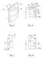
- FIG. 1 is a side elevation view of a system for inductively providing power to an electrical device according to the present invention.
- FIG. 2 is a schematic view of an induction assembly of the system depicted in FIG. 1 .
- FIG. 3 is a schematic view of a load assembly of the depicted in FIG. 1 .
- FIG. 4 is a perspective view of the system according to an embodiment of the present invention as depicted in FIG. 1 in a first orientation.
- FIG. 5 is another perspective view of the system according to an embodiment of the present invention as depicted in FIG. 2 in a second orientation.
- FIG. 6 is a schematic view of an induction assembly of a system for inductively powering an electrical device according to an embodiment of the present invention.
- FIG. 7 is a schematic view of a load assembly of a system for inductively powering an electrical device according to an embodiment of the present invention.
- FIG. 8 is a schematic view of an induction assembly of a system for inductively powering an electrical device according to an embodiment of the present invention.
- FIG. 9 is a schematic view of a load assembly of a system for inductively powering an electrical device according to an embodiment of the present invention.
- FIG. 10 is a schematic view of a load assembly of a system for inductively powering an electrical device according to an embodiment of the present invention.
- an embodiment of the invention provides a system for inductively powering and remotely attaching an electrical device. More specifically, the system may include an induction assembly and a load assembly.
- the induction assembly may be configured to generate an induction field that inductively couples with an electrical device disposed within the load assembly so as to provide power to the electrical device, thereby energizing and enabling the operation of the electrical device.
- a system 100 for inductively powering an electrical device is depicted having an induction assembly 110 and a load assembly 150 .
- the induction assembly 110 may include a housing 112 that is configured to have disposed therein the various operational elements of the induction assembly 110 .
- the load assembly 150 may include a housing 151 that is configured to have disposed therein the various operational elements of the bad assembly 150 .
- the induction assembly 110 may further include an induction circuit 114 .
- the induction circuit 114 may be designed as any circuit known to generate a magnetic field that is functional to electromagnetically induce an electric current in a corresponding receiver circuit, a phenomenon known as inductive coupling.
- the induction circuit 114 may include a solenoid 116 , a coil of wire that acts as an electrical conductor, permitting the flow of current therethrough. As current travels through the solenoid 116 , it generates a magnetic field proportional to the amount of current passing through the solenoid 116 according to Faraday's law, which is represented by the equation
- the induction circuit may further include other electrical components, including resistors, capacitors, diodes, transistors, amplifiers, and any other components that facilitate the induction of a magnetic field through the solenoid 116 .
- the solenoid 116 may be configured to be capacitively loaded by one or more capacitors so that the induction circuit 114 may form a resonant circuit. It is known in the art that resonant inductively coupling has an efficiency advantage over non-resonant inductive coupling systems.
- the resonant frequency of the induction circuit may be determined, or the components of the induction circuit 114 may be selected to produce a circuit with a desired resonant frequency, by the equation
- ⁇ ⁇ 1 LC
- w the angular frequency
- L the inductance of the solenoid 116
- C the capacitance of one or more capacitors of the induction circuit 114 .
- the amount of energy lost between the induction circuit 114 and a corresponding receiver circuit may be determined by the equation
- Q 1 R ⁇ L C
- Q is a factor that characterizes the damping of the induction circuit 114
- R is the resistance of at least one resistor of the induction circuit 114 .
- a higher Q factor results in a lower amount of energy lost in the transfer of energy between the induction circuit 114 and a receiver circuit.
- the various components of the induction circuit 114 may be configured and arranged to result in a circuit having a desirable resonant frequency and Q factor so as to reduce the amount of energy lost in transfer to a receiver circuit.
- the induction circuit 114 may further include a first connector 118 that enables the induction circuit 114 to be connected to a power source 111 , and a second connector 120 that enables the induction circuit 114 to be connected to other elements of the induction assembly 110 . Additionally, the induction circuit 114 may include electrical components necessary to convert power supplied by the power source 111 into electricity of appropriate voltage, current, and modulation for operation of the induction circuit 114 .
- the induction assembly 110 may further include a switch 122 .
- the switch 122 may be configured to have a first state and a second state, and further may be transitionable between the first and second states.
- the switch 122 may be caused to transition between the first and second states, and vice versa, by a triggering event.
- the triggering event may include, but is not limited to, the presence or absence of an electromagnetic field and receiving an electronic instruction or command.
- the switch 122 may be configured to transition from the first state to the second state when a magnetic field is generated within proximity of the switch 122 .
- switches are known to have this type of functionality, including, without limitation, reed switches and Hall effect sensors. Where a Hall effect sensor is used, the switch 122 may further include circuitry that enables the sensor to function as a switch, as well as providing the necessary input voltage for the functioning of the switch. Accordingly, the switch 122 may include a connector that is electrically coupled to a power source. The switch 122 may be configured to transition from the first state to the second state when a magnetic field of sufficient strength, intensity, induction, or flux density above a threshold value is incident upon the switch 122 .
- the switch 122 may include a first connector 124 and a second connector 126 that may be configured to connect to other elements of the induction assembly.
- the first connector 124 may be connected to and in electric communication with the second connector 120 of the induction circuit 114 .
- the second connector 126 may be configured to connect to an electric ground of the power source 111 .
- the first and second states of the switch 122 may be configured to control the operation of the induction circuit 114 . More specifically, the first state of the switch 122 may be described as being in an open state, meaning that there is no electrical connection between the first connector 124 and the second connector 126 of the switch 122 , preventing the flow of electrical current therethrough. In the present embodiment, where the switch is connected to and functionally and electrically coupled with the induction circuit 114 , when the switch 122 is in the first state, no electric current may flow through the switch 122 , and as there is no other path to an electric ground, currently accordingly may not flow through the induction circuit 114 .
- the switch 122 When the switch 122 is in the second state, the switch may be described as being in a closed state, meaning that there is an electrical connection between the first connector 124 and the second connector 126 of the switch 122 , enabling the flow of current therethrough. In the present embodiment, when the switch 122 is in the second state, the flow of current through the switch 122 provides a path to an electrical ground for the induction circuit 114 , thereby enabling the operation of the induction circuit 114 .
- the induction assembly 110 may further include an induction attaching device 128 .
- the induction attaching device 128 may be configured to couple to a corresponding attaching device in another structure, device, or assembly, such as, for instance, the load assembly 150 as shown in FIG. 1 .
- the coupling between the induction attaching device 128 and the corresponding attaching device may be accomplished remotely and at a distance.
- the coupling between the induction attaching device 128 and the corresponding attaching device may cause a remote attaching between the induction assembly 110 and the structure, device, or assembly containing the corresponding device, such as the load assembly 150 , so that the load assembly 150 is prevented from moving with respect to the induction assembly 110 absent the influence of any outside force, aside from any force exerted by gravity.
- the induction attaching device 128 may be any device that exerts a force on a corresponding attaching device so as to prevent the movement of the structure, device, or assembly containing the corresponding device with respect to the induction assembly.
- This attaching force may, for example, be exerted by the interaction between magnetic or electromagnetic fields between the induction attaching device 128 and the corresponding attaching device.
- the induction attaching device 128 is a magnet.
- the induction attaching device 128 may be a magnet that generates a magnetic field of sufficient strength, intensity, induction, or flux density to exert a force upon a corresponding attaching device in the load assembly 150 , thereby coupling the induction attaching device 128 and the corresponding attaching device so as to remotely attach the load assembly 150 to the inductor assembly 110 , preventing any relative movement therebetween.
- the induction attaching device 128 may be any type of suitable magnet, including, by way of example only and not as a limitation, permanent magnets and electromagnets.
- the strength, intensity, induction, or flux density of a magnetic field decreases proportionally as the distance between the induction attaching device 128 and the corresponding attaching device increases. Therefore, the induction attaching device 128 may be configured to generate a magnetic field that exerts a sufficient force to remotely attach the load assembly 150 , as depicted in FIG. 1 , at some distance from the induction assembly 110 .
- both the induction assembly 110 and the load assembly 150 are depicted as being attached to a structure 190 .
- the structure 190 may be a wall, for instance, a wall of known thickness.
- the structure 190 may be a table, desk, ceiling, household, commercial, or industrial appliance, console, automobile dashboard, or any other structure where it may be desirable to have the capability of inductively powering and remotely attaching an electrical device.
- the induction assembly 110 may be positioned in electronic communication with an external computerized device.
- the external computerized device may be configured to monitor the operation, power consumption, or any other operational characteristic of the induction assembly 110 .
- the induction assembly 110 may include a microcontroller positioned into said electronic communication.
- the microcontroller may be positioned in communication with the various elements of induction assembly 110 , including the induction circuit 114 , switch 122 , and induction attaching device 128 so as to acquire operational information about said elements in order to relay such information to the external computerized device. Accordingly, the operation of the induction assembly 110 , and by extension the system 100 , may be monitored.
- the communication may be accomplished by any wired communication, including standards such as Ethernet, Universal Serial Bus (USB), FireWire, and Thunderbolt, as well as various forms of wireless communication, including 802.11/WiFi networking standards, Bluetooth, Zigbee, RuBee, Near-Field Communication (NFC), and any other methods and/or standards of wireless communication known in the art.
- the induction assembly 110 may include electronic devices capable of accomplishing such methods of communication.
- the load assembly 150 may include a receiver circuit 152 .
- the receiver circuit 152 may be configured to inductively couple with the induction circuit 114 of the inductor assembly 110 so as to receive electric power from the induction circuit 114 .
- the receiver circuit 152 may include a solenoid 154 , a coil of wire that permits the flow of electrical current therethrough.
- the solenoid 154 may be configured to permit a flow of current to be induced through the wire when in the presence of a magnetic field.
- the receiver circuit 152 may be configured to form a resonant inductive coupling with the induction circuit 114 . Accordingly, where the induction circuit 114 is configured to have a resonant frequency, the receiver circuit 152 may include electrical components so as to configure the receiver circuit 152 to have a resonant frequency that is approximately equal to the resonant frequency of the induction circuit 114 .
- the receiver circuit 152 may include a first connector 156 and a second connector 158 , each of which may be connected to other elements of the load assembly 150 .
- the load assembly 150 may further include an electrical device 160 .
- the electrical device 160 may be any device capable of being energized and rendered operable by electric power that is induced in the receiver circuit 152 .
- Types of electrical devices that are contemplated for use in connection with the present invention include, without limitation, illuminants, electronic visual displays, photograph capture devices, video capture devices, loudspeakers, microphones, devices including a microcontroller, such as telephones, mobile telephones, GPS devices, and any accompanying circuitry.
- a microcontroller such as telephones, mobile telephones, GPS devices, and any accompanying circuitry.
- the electrical device 160 may be an illuminant, which may be any device capable of emitting light upon being energized.
- illuminants include, without limitation, incandescent light bulbs, fluorescent light bulbs, high-intensity discharge bulbs, and light-emitting semiconductors, such as light-emitting diodes (LEDs), and lasers.
- the electrical device 160 may comprise an array of illuminants, such as an array of LEDs.
- the electrical device 160 is an LED 161 . When the LED 161 is energized, it operates to emit light.
- the LED 161 may be positioned relative to the other elements of the load assembly 150 and within the housing 151 so as to emit light in a desired direction. Accordingly, the housing 151 may include an aperture through which light emitted from the LED 161 may travel through and into the environment surrounding the load assembly 150 .
- the load assembly 150 may further include a triggering device 162 .
- the triggering device 162 may be configured to interact with the switch 122 of the induction assembly 110 so as to transition the switch between the first and second states.
- the triggering device 162 may be any device or mechanism that has properties or performs functions that operate as the triggering event for the switch 122 .
- the switch 122 is a device that has a triggering event of the presence or absence of a magnetic field
- the triggering device 162 may be a magnet.
- the triggering device may be a magnet of any type, including, without limitation, electromagnets and permanent magnets.
- the triggering device 162 may be a triggering magnet 163 .
- the triggering magnet 163 may be configured to generate a magnetic field of sufficient strength, intensity, induction, or flux density so as to effectuate the transition between the first and second states of the switch 122 .
- the force exerted by a magnetic field upon an incident object may indirectly vary with the distance between the field source and the object.
- the switch 122 may be caused to transition between the first state and the second state when the magnetic field generated by the triggering magnet 163 is brought within a proximate distance of the switch 122 such that the triggering magnet 163 exerts a magnetic force above a threshold magnetic force on the switch 122 .
- the switch 122 and the triggering magnet 163 may be configured so that, when the triggering magnet 163 is at or within a known and/or predetermined distance from the switch 122 , the force exerted by the magnetic field generated by the triggering magnet 163 is equal to or greater than the threshold magnetic force necessary to transition the switch 122 between the first and second states
- the magnetic field generated by the triggering magnet 163 may be configured to account for the separation between the induction assembly 110 and the load assembly 150 as depicted in FIG. 1 , as well as the electromagnetic permittivity of any intermediate material, discussed in greater detail hereinbelow.
- the triggering device 162 may be a device that communicates with the switch 122 via wireless communication with a trigger-detecting electronic device of the induction assembly 110 capable of performing wireless communication. Accordingly, the trigger-detecting electronic device may be included as part of the switch 122 or be disposed adjacent to the switch 122 in the induction assembly 110 and functionally coupled to the switch 122 , such that trigger-detecting electronic device may enable the switch to transition between the first and second states described hereinabove.
- the triggering device 162 may be a radio-frequency identification (RFID) tag as is well known in the art. The trigger-detecting electronic device may detect the presence of the triggering device 162 within its proximity and cause the switch to transition between the first and second states.
- RFID radio-frequency identification
- the load assembly 150 may further include a load attaching device 164 .
- the load attaching device 164 of the load assembly 150 may be configured to interact with and couple to the induction attaching device 128 of the induction assembly 110 .
- the coupling between the induction attaching device 128 and the load attaching device 164 may cause the induction attaching device 128 to exert a force on the load attaching device 164 as described hereinabove, wherein the load attaching device 164 functions as the corresponding attaching device.
- the force exerted on the load attaching device 164 by the induction attaching device 128 may prevent the movement of the load assembly 150 with respect to the induction assembly 110 , discussed in greater detail hereinbelow.
- the load attaching device 164 may be any device or mechanism that has properties or performs functions that operate to couple with the induction attaching device 128 of the induction assembly 110 .
- the load attaching device 164 may be a device that is responsive to and affected by a magnetic field. More specifically, the load attaching device 164 may be any device that, when in the presence of the magnetic field generated by the induction attaching device 128 , has a force exerted upon the load attaching device 164 sufficient to removably attach the load assembly 150 to a structure.
- the force exerted upon the load attaching device 164 may be configured to be sufficiently weak to permit the de-coupling of the induction attaching device 128 and the load attaching device 164 , and hence detachment of the load assembly 150 , by the exertion of a force by a user, installer, or any other person or device that is attempting to detach the load assembly 150 from the structure 190 , shown in FIG. 1 .
- the load attaching device 164 may be a magnet of any type, including, without limitation, electromagnets and permanent magnets. In the present embodiment, the load attaching device 164 may be a magnet 165 .
- the induction assembly 110 may be attached to a first surface 192 of the structure 190 , and the load assembly 150 may be attached to a second surface 194 of the structure. More specifically, the housing 112 of the induction assembly 110 may be configured to facilitate the attachment of the induction assembly 110 to the first surface 192 by enabling fasteners to fixedly attach the housing to the first surface 192 . Any type of fastener may be used, including screws, nails, staples, welds, glues, adhesives, or any other suitable fastening mechanism.
- the properties of the materials used in the structure may be known, particularly those properties that may be relevant to the attachment of the load assembly 150 to the second surface 194 of the structure 190 .
- the electromagnetic permittivity of the materials used in the structure 190 may be considered and accounted for in the configuration of the switch 122 , triggering device 162 , induction attaching device 128 , and load attaching device 164 .
- the electromagnetic permittivity of the materials in the structure 190 may be considered when configuring the threshold magnetic force of the switch 122 , the magnitude of the magnetic field generated by the triggering magnet 163 , and magnetic force exerted upon the load attaching device 164 , which may be accomplished by selective configuration of the magnetic fields generated by and/or exposed to the induction attaching device 128 and load attaching device 164 .
- the surface properties for the second surface 194 may be considered in configuration of the induction attaching device 128 and the load attaching device 164 . More specifically, the static and kinetic frictional forces resulting from the force exerted by the coupling between the attaching devices 128 and 164 may be configured to prevent the relative movement of the induction assembly 110 and the load assembly 150 in the presence of external forces, including, as an example only and not by means of limitation, gravity.
- the induction attaching device 128 and the load attaching device 164 are magnets. Accordingly, the positioning and orientation of the induction attaching device 128 and the load attaching device 164 is determinative in the coupling between them and the magnetic force exerted upon each, most importantly on the load attaching device 164 . As shown in FIG. 4 , when the induction assembly 110 and the load assembly 150 are in a first orientation with respect to each other, the induction attaching device 128 and the load attaching device 164 are able to couple to each other and exert the necessary force upon the load attaching device 164 to prevent relative movement between the induction assembly 110 and the load assembly 150 .
- the longitudinal axes of the induction assembly 110 and the load assembly 150 are in a generally parallel orientation.
- the longitudinal axes of the induction assembly 110 and the load assembly 150 are in a generally perpendicular orientation.
- the induction attaching device 128 and the load attaching device 164 are not coupled to each other, or the coupling therebetween results in the exertion of a force upon the load attaching device 164 that is insufficient to attach the load assembly 150 to the structure 190 .
- the load assembly 150 is not attached to the second surface 194 of the structure 190 , and may be removed.
- the transition between the respective orientations of the induction assembly 110 and the load assembly 150 depicted between FIGS. 4 and 5 may be accomplished by the exertion of a force by a person who is attempting to alter the attachment of the load assembly 150 to the structure 190 .
- the user may interface the load assembly 150 with the second surface 194 of the structure 190 in a position that is generally opposite the position to which the induction assembly 110 is attached to the first surface 192 of the structure 190 in an initial orientation that is generally perpendicular to orientation of the induction assembly 110 , such that the induction attaching device 128 and the load attaching device 164 are not coupled or are ineffectively coupled.
- the user may then reorient the load assembly 150 to an orientation that is generally parallel to the induction assembly 110 , thereby coupling the induction attaching device 128 and the load attaching device 164 , thereby attaching the load assembly 150 to the second surface 194 of the structure 190 .
- the relative orientations of the induction assembly 110 and the load assembly 150 may be configured such that coupling between the induction attaching device 128 and the load attaching device 164 occurs when the relative orientations of the induction assembly 110 and the load assembly 150 are desirable.
- the induction assembly 610 may include an induction circuit 612 substantially as described as the induction circuit of FIGS. 1-5 , having a solenoid 614 and first and second connectors 616 and 618 .
- the induction assembly 610 may include a switch 620 .
- the switch 620 in the present embodiment may be a Hall effect switch 621 capable of determining the magnitude of the strength, intensity, induction, or flux density of an incident magnetic field.
- the Hall effect 621 switch may be configured to transition between first and second states when a magnetic field having strength, intensity, induction, or flux density above a threshold value is incident upon the Hall effect switch 621 .
- the Hall effect switch 621 may be configured to provide an indication of the magnitude of the strength, intensity, induction, or flux density of an incident magnetic field to another device or mechanism that is functionally coupled to or in communication with the Hall effect switch 621 , discussed in greater detail hereinbelow.
- the induction assembly 610 of the present embodiment may further include an attaching device 622 .
- the attaching device 622 may be an electromagnetic circuit 624 having an electromagnet 625 , which are known in the rt.
- An example of an electromagnet is a solenoid having a ferromagnetic material disposed within an interior diameter of the solenoid.
- the electromagnet 625 includes first and second connectors 626 and 628 configured to permit the flow of electricity through the electromagnet 625 , thereby enabling the electromagnet to generate a magnetic field. Accordingly, the electromagnet 625 may have an operative state when current flows through the solenoid, and a non-operative state when current is not flowing through the solenoid.
- the magnitude of the strength, intensity, induction, or flux density of the agnetic field generated by the electromagnet 625 may be controlled and selectively generated by manipulating the amount of current that is passed through the electromagnet 625 .
- the induction assembly 610 may further include a current regulating device 630 .
- the current regulating device 630 may be configured to control the amount of current that is delivered to the electromagnet 625 .
- the magnetic field generated by the electromagnet 625 may be controlled and manipulated through the operation of the current regulating device 630 .
- the induction assembly 610 of the present embodiment may include a Hall effect switch 621 configured to determine the magnitude of the strength, intensity, induction, or flux density of a magnetic field incident thereupon, and to provide an indication of that magnitude.
- the current regulating device 630 may be configured to functionally couple to and be in electronic communication with the Hall effect switch 621 such that the indication of the magnitude of the incident magnetic field on the Hall effect switch 621 controls the operation of the current regulating device 630 .
- the current regulating device 630 may deliver a first current to the electromagnet 625 , thereby producing a magnetic field having a first strength, intensity, induction, or flux density, and where a magnetic field having a second magnitude of strength, intensity, induction, or flux density is detected by the Hall effect switch 621 , the current regulating device 630 may deliver a second current to the electromagnet 625 , thereby producing a magnetic field having a second strength, intensity, induction, or flux density.
- the indication provided by the Hall effect switch 621 may be configured to vary directly or indirectly to the magnitude detected of the incident magnetic field.
- the current regulating device 630 may be a microprocessor configured to control the delivery of current in proportion to an input voltage.
- the indication provided by the Hall effect switch 621 may be a voltage that is proportional to the magnitude of a characteristic of the magnetic field detected by the Hall effect switch 621 .
- the voltage indicated by the Hall effect switch 621 may function as the input voltage for the current regulating device 630 .
- the microcontroller of the current regulating device 630 may measure the input voltage and deliver a current that is proportional to the input voltage.
- the determination of the current to be delivered may be based on a calculation performed by the microprocessor.
- the microprocessor may be programmed to include the formulae necessary to perform such a calculation, as are well known in the art.
- the load assembly 700 of the present embodiment is substantially similar to the load assembly as depicted in FIGS. 1-5 .
- the load assembly 700 may include a receiver 702 , an electrical device 704 , an attaching device 706 , and a triggering device 708 substantially as described above.
- a triggering device 708 substantially as described above.
- the triggering device 708 may be configured to generate a magnetic field that is detected as having a desired magnitude of strength, intensity, induction, or flux density by the Hall effect switch 621 , thereby resulting in the electromagnet 625 generating a magnetic field of a desired strength, intensity, induction, or flux density.
- the electromagnet 625 is the attaching device 622 of the induction assembly 610
- the magnetic field generated by the electromagnet 625 causes the electromagnet 625 to couple with the attaching device 706 and to exert a force on the attaching device 706 , thereby attaching the load assembly substantially as described above. Therefore, the triggering device 708 may be configured to result in a desired force to be exerted upon the attaching device 706 . This may permit the induction assembly 600 as depicted in FIG. 6 to couple to varying load assemblies, varying the force exerted on the respective attaching device of the varying load assemblies.
- a first load assembly may have a first triggering device configured to generate a first magnetic field.
- the first magnetic field may cause result in a first force to be exerted on a first attaching device of the first load assembly.
- the first force may be configured to be only sufficiently strong to prevent the relative movement between the induction assembly and the first load assembly.
- a second load assembly may include a second triggering device configured to generate a second magnetic field, the second magnetic field resulting in a second force to be exerted on a second attaching device of the second load assembly. That second force may similarly be only sufficiently strong to prevent the relative movement between the induction assembly and the second load assembly. That second force may be greater or less than the first force, or it may be approximately equal to the first force.
- a single inductive assembly may be functional to couple to varying load assemblies requiring differing forces to be exerted upon their respective attaching devices in order to prevent their relative movement to the induction assembly.
- FIG. 8 an alternative embodiment of the present invention is depicted.
- the induction assembly 800 may be similar to the embodiments of the induction assemblies as depicted in FIGS. 1-5 and 6 - 7 .
- the induction assembly 800 may include an induction circuit 802 having a solenoid 803 , a switch 804 , and an attaching device 806 .
- the switch 804 may be a Hall effect switch 805 capable of determining the magnitude of the strength, intensity, induction, or flux density of an incident magnetic field.
- the Hall effect 805 switch may be configured to switch between first and second states when a magnetic field having strength, intensity, induction, or flux density above a threshold value is incident upon the Hall effect switch 805 .
- the Hall effect switch 805 may be configured to provide an indication of the magnitude of the strength, intensity, induction, or flux density of an incident magnetic field to another device or mechanism that is functionally coupled to or in communication with the Hall effect switch 805 .
- the present embodiment of the induction assembly 800 may further include a current regulating device 808 .
- the current regulating device 808 may be functionally coupled to and in electric communication with the induction circuit 802 .
- the functional coupling between the current regulating device 808 and the induction circuit 802 may permit the current regulating device 808 to selectively deliver currents of varying amperage to the induction circuit 802 .
- the varying of current delivered to the induction circuit 802 varies the current that passes through the solenoid 803 , thereby varying the magnetic field generated by the solenoid 803 .
- the inductive coupling between the induction circuit 802 and a corresponding receiver circuit may be manipulated and selectively controlled by the amount of current delivered by the current regulating device 808 .
- the amount of power delivered by the induction circuit 802 via the inductive coupling may be varied.
- the induction assembly 800 of the present embodiment may include a Hall effect switch 805 configured to determine the magnitude of the strength, intensity, induction, or flux density of a magnetic field incident thereupon, and to provide an indication of that magnitude.
- the current regulating device 808 may be configured to functionally couple to and be in electronic communication with the Hall effect switch 805 such that the indication of the magnitude of the characteristic of the incident magnetic field on the Hall effect switch 805 controls the operation of the current regulating device 808 .
- the current regulating device 808 may deliver a first current to the induction circuit 802 , thereby causing the solenoid 803 to produce a magnetic field having a first strength, intensity, induction, or flux density, and where a magnetic field having a second magnitude of strength, intensity, induction, or flux density is detected by the Hall effect switch 805 , the current regulating device 808 may deliver a second current to the induction circuit 802 , thereby causing the solenoid 803 to produce a magnetic field having a second strength, intensity, induction, or flux density.
- the indication provided by the Hall effect switch 805 may be configured to vary directly or indirectly to the magnitude detected of the incident magnetic field.
- the load assembly 900 of the present embodiment is substantially similar to the load assemblies depicted in FIGS. 1-5 and 7 .
- the load assembly 900 may include a receiver circuit 902 , an electrical device 904 , an attaching device 906 , and a triggering device 908 substantially as described above.
- the triggering device 908 may be configured to generate a magnetic field that is detected as having a desired magnitude of strength, intensity, induction, or flux density by the Hall effect switch 805 , thereby resulting in the induction circuit 802 , and hence the solenoid 803 , generating a magnetic field of a desired strength, intensity, induction, or flux density.
- the induction circuit 802 is configured to inductively couple with the receiver circuit 902 , thereby delivering power to the receiver circuit 902 .
- the triggering device 908 may be configured so as to cause the induction circuit 802 to generate a magnetic field of desired strength, intensity, induction, or flux density so as to deliver a desired amount of power to the receiver circuit 902 .
- This may permit the induction assembly 800 to deliver varying amounts of power to varying bad assemblies, varying the magnetic field generated by the inductive circuit 802 in response to the varying triggering devices of the respective bad assemblies.
- a first bad assembly may have a first triggering device configured to generate a first magnetic field.
- the first magnetic field may cause a first inductive magnetic field to be generated by the induction circuit of an induction assembly, thereby delivering a first amount of power to the first bad assembly.
- the first amount of power may be configured to provide sufficient power for the operation of a first electrical device of the first bad assembly.
- a second load assembly may include a second triggering device configured to generate a second magnetic field, the second magnetic field resulting in a second inductive magnetic field being generated by the induction circuit, thereby deliver a second amount of power to the second load assembly.
- the second amount of power may be configured to provide sufficient power for the operation of a second electrical device of the second bad assembly.
- That second amount of power may be greater or less than the first amount of power, or it may be approximately equal to the first amount of power. Accordingly, a single inductive assembly may be functional to deliver varying amounts of power to varying bad assemblies requiring differing amounts of power for operation of their respective electrical devices.
- the load assembly 1000 may be similar to the various embodiments of the load assemblies depicted in the application. More specifically, the load assembly may include a receiver circuit 1002 configured to inductively couple with an induction circuit, an electrical device 1004 functionally coupled to and in electric communication with the receiver circuit 1002 , an attaching device 1006 , and a triggering magnet 1008 .
- the attaching device 1006 may be an electromagnet 1010 .
- the electromagnet 1010 may be any type of electromagnet, such as, for example, a solenoid with a ferromagnetic material disposed within an interior diameter of the solenoid. Accordingly, the electromagnet 1010 may be functionally coupled to and in electric communication with the receiver circuit 1002 , enabling electricity to flow through the electromagnet 1010 , thereby generating a magnetic field.
- the load assembly 1000 may be configured to be operable with an induction assembly as depicted in FIG. 8 , the induction assembly having operational capabilities according to the corresponding description. Accordingly, the triggering magnet 1008 of the load assembly 1000 may be configured to generate a magnetic field of specific strength, intensity, induction, or flux density, which is detected by a Hall effect switch of the induction assembly at a desired magnitude, thereby causing the induction circuit of the induction assembly to generate a desired magnetic field.
- the receiver circuit 1002 may be configured to inductively couple with the induction circuit, thereby receiving power from the induction circuit.
- the functional coupling between the receiver circuit 1002 and the electromagnet 1010 enables the delivery of current from the receiver circuit 1002 to the electromagnet.
- the delivery of current to the electromagnet 1010 causes the electromagnet 1010 to generate a magnetic field.
- the magnetic field generated by the electromagnet 1010 is proportional to the current delivered to the electromagnet 1010 .
- the magnetic field generated by the electromagnet 1010 may be configured to couple the electromagnet 1010 to an attaching device of the induction assembly, thereby resulting in a force being exerted on the electromagnet 1010 substantially as described above, thereby attaching the load assembly 1000 to a surface and preventing movement of the load assembly 1000 with respect to the induction assembly.
- the receiver circuit 1002 may further include electrical components configured to deliver current in desired amounts to each of the electrical device 1004 and the electromagnet 1010 . More specifically, the electrical device 1004 may require a certain amount of power to operate. Furthermore, the amount of power delivered to the receiving circuit 1002 may be anticipated, and the voltage of the power delivered may similarly be anticipated. Yet further, the magnetic field desired to be generated by the electromagnet 1010 may be known, as well as the amount of current necessary for the electromagnet 1010 to generate that magnetic field.
- the receiver circuit 1002 may include circuitry to deliver sufficient current of appropriate voltage to each of the electrical device 1004 and the electromagnet 1010 so as to both operate the electrical device 1004 and to enable the electromagnet 1010 to generate a magnetic field of sufficient strength, intensity, induction, or flux density so as to couple with an attaching device of an induction assembly, thereby causing a force to be exerted upon the electromagnet 1010 , attaching the load assembly 1000 to a surface of a structure and preventing the movement of the load assembly 1000 relative to the induction assembly.
- a first load assembly may have a first triggering device configured to generate a first magnetic field.
- the first magnetic field may cause a first inductive magnetic field to be generated by the induction circuit of an induction assembly, thereby delivering a first amount of power to a first receiver circuit of the first load assembly.
- the first receiver circuit may then deliver current to a first electrical device and a first electromagnet, thereby causing the first electrical device to operate and the first electromagnet to generate a first attaching magnetic field.
- the first attaching magnetic field may couple with an attaching device of the induction assembly resulting in a first force to be exerted upon the first electromagnet and, hence, the first load assembly.
- the first force may be configured to be only sufficiently strong to prevent the relative movement between the induction assembly and the first load assembly.
- a second load assembly may include a second triggering device configured to generate a second magnetic field, the second magnetic field resulting in a second inductive magnetic field being generated by the induction circuit, thereby deliver a second amount of power to a second receiver circuit of the second load assembly.
- the second receiver circuit may then deliver current to a second electrical device and a second electromagnet, thereby causing the second electrical device to operate and the second electromagnet to generate a second attaching magnetic field.
- the second attaching magnetic field may couple with the attaching device of the induction assembly resulting in a second force to be exerted upon the second electromagnet and, hence, the second load assembly.
- That second force may similarly be only sufficiently strong to prevent the relative movement between the induction assembly and the second load assembly. That second force may be greater or less than the first force, or it may be approximately equal to the first force. Similarly, the second amount of power may be greater or less than the first amount of power, or approximately equal to the first amount of power. Accordingly, a single inductive assembly may be functional to couple to varying load assemblies requiring differing forces to be exerted upon their respective electromagnets in order to prevent their relative movement to the induction assembly.
Landscapes
- Engineering & Computer Science (AREA)
- Power Engineering (AREA)
- General Engineering & Computer Science (AREA)
- Manufacturing & Machinery (AREA)
- Microelectronics & Electronic Packaging (AREA)
- Magnetic Treatment Devices (AREA)
Abstract
Description
where B is the induced magnetic field, μ0 is the magnetic constant, N is the number of turns in the coil forming the
where w is the angular frequency, L is the inductance of the
where Q is a factor that characterizes the damping of the
Claims (21)
Priority Applications (1)
| Application Number | Priority Date | Filing Date | Title |
|---|---|---|---|
| US13/608,999 US8847436B2 (en) | 2011-09-12 | 2012-09-10 | System for inductively powering an electrical device and associated methods |
Applications Claiming Priority (2)
| Application Number | Priority Date | Filing Date | Title |
|---|---|---|---|
| US201161533570P | 2011-09-12 | 2011-09-12 | |
| US13/608,999 US8847436B2 (en) | 2011-09-12 | 2012-09-10 | System for inductively powering an electrical device and associated methods |
Publications (2)
| Publication Number | Publication Date |
|---|---|
| US20130099696A1 US20130099696A1 (en) | 2013-04-25 |
| US8847436B2 true US8847436B2 (en) | 2014-09-30 |
Family
ID=48135411
Family Applications (1)
| Application Number | Title | Priority Date | Filing Date |
|---|---|---|---|
| US13/608,999 Active 2032-11-24 US8847436B2 (en) | 2011-09-12 | 2012-09-10 | System for inductively powering an electrical device and associated methods |
Country Status (1)
| Country | Link |
|---|---|
| US (1) | US8847436B2 (en) |
Cited By (6)
| Publication number | Priority date | Publication date | Assignee | Title |
|---|---|---|---|---|
| US9693414B2 (en) | 2011-12-05 | 2017-06-27 | Biological Illumination, Llc | LED lamp for producing biologically-adjusted light |
| US10283952B2 (en) | 2017-06-22 | 2019-05-07 | Bretford Manufacturing, Inc. | Rapidly deployable floor power system |
| US10386021B2 (en) * | 2017-11-27 | 2019-08-20 | Shenzhen Guanke Technologies Co., Ltd. | LED light |
| US11274019B2 (en) * | 2017-05-17 | 2022-03-15 | Kone Corporation | Wireless power transfer arrangement for an elevator car and an elevator |
| US11561639B2 (en) * | 2017-11-13 | 2023-01-24 | Samsung Electronics Co., Ltd. | Display device and control method for performing operations relating to user input and display state |
| US12142935B2 (en) | 2021-10-11 | 2024-11-12 | Ford Global Technologies, Llc | Baseplate inductive electrical connection |
Families Citing this family (22)
| Publication number | Priority date | Publication date | Assignee | Title |
|---|---|---|---|---|
| US8841864B2 (en) | 2011-12-05 | 2014-09-23 | Biological Illumination, Llc | Tunable LED lamp for producing biologically-adjusted light |
| US8686641B2 (en) | 2011-12-05 | 2014-04-01 | Biological Illumination, Llc | Tunable LED lamp for producing biologically-adjusted light |
| US9827439B2 (en) | 2010-07-23 | 2017-11-28 | Biological Illumination, Llc | System for dynamically adjusting circadian rhythm responsive to scheduled events and associated methods |
| US8760370B2 (en) | 2011-05-15 | 2014-06-24 | Lighting Science Group Corporation | System for generating non-homogenous light and associated methods |
| US9024536B2 (en) | 2011-12-05 | 2015-05-05 | Biological Illumination, Llc | Tunable LED lamp for producing biologically-adjusted light and associated methods |
| US9532423B2 (en) | 2010-07-23 | 2016-12-27 | Lighting Science Group Corporation | System and methods for operating a lighting device |
| US8847436B2 (en) | 2011-09-12 | 2014-09-30 | Lighting Science Group Corporation | System for inductively powering an electrical device and associated methods |
| US9220202B2 (en) | 2011-12-05 | 2015-12-29 | Biological Illumination, Llc | Lighting system to control the circadian rhythm of agricultural products and associated methods |
| US9289574B2 (en) | 2011-12-05 | 2016-03-22 | Biological Illumination, Llc | Three-channel tuned LED lamp for producing biologically-adjusted light |
| US8963450B2 (en) | 2011-12-05 | 2015-02-24 | Biological Illumination, Llc | Adaptable biologically-adjusted indirect lighting device and associated methods |
| US9827502B2 (en) * | 2012-01-26 | 2017-11-28 | Activision Publishing, Inc. | Interactive video game with toys having special effects |
| US9151453B2 (en) | 2013-03-15 | 2015-10-06 | Lighting Science Group Corporation | Magnetically-mountable lighting device and associated systems and methods |
| US9222653B2 (en) | 2013-03-15 | 2015-12-29 | Lighting Science Group Corporation | Concave low profile luminaire with magnetic lighting devices and associated systems and methods |
| US9157618B2 (en) | 2013-03-15 | 2015-10-13 | Lighting Science Group Corporation | Trough luminaire with magnetic lighting devices and associated systems and methods |
| WO2017165432A1 (en) * | 2016-03-21 | 2017-09-28 | Google Incorporated | Modular lighting control system |
| US11085977B2 (en) * | 2017-05-15 | 2021-08-10 | Wisconsin Alumni Research Foundation | Method and apparatus for integrating current sensors in a power semiconductor module |
| US20190340872A1 (en) | 2018-05-01 | 2019-11-07 | Igt | Wireless user interface elements for gaming devices |
| IT201800007228A1 (en) * | 2018-07-16 | 2020-01-16 | Electric power supply device for electrical loads in environments with risk of explosion | |
| WO2020028088A1 (en) * | 2018-07-31 | 2020-02-06 | Earlens Corporation | Intermodulation distortion reduction in a contact hearing system |
| US12101138B2 (en) * | 2019-09-19 | 2024-09-24 | Sensormatic Electronics, LLC | Self-detaching anti-theft device using direct and harvested resonant energy |
| US11156022B2 (en) | 2019-09-20 | 2021-10-26 | Sensormatic Electronics, LLC | Tack with free spinning feature |
| US12481797B2 (en) * | 2022-12-29 | 2025-11-25 | Blackberry Limited | Internet-of-things devices and methods of controlling power thereto |
Citations (101)
| Publication number | Priority date | Publication date | Assignee | Title |
|---|---|---|---|---|
| US5221877A (en) | 1992-03-10 | 1993-06-22 | Davis Controls Corporation | Power reduction control for inductive lighting installation |
| US5523878A (en) | 1994-06-30 | 1996-06-04 | Texas Instruments Incorporated | Self-assembled monolayer coating for micro-mechanical devices |
| US5680230A (en) | 1993-09-09 | 1997-10-21 | Canon Kabushiki Kaisha | Image processing method and apparatus thereof |
| US5704701A (en) | 1992-03-05 | 1998-01-06 | Rank Brimar Limited | Spatial light modulator system |
| US5997150A (en) | 1995-10-25 | 1999-12-07 | Texas Instruments Incorporated | Multiple emitter illuminator engine |
| US6027225A (en) | 1997-12-24 | 2000-02-22 | Martin; William E. | Battery powered light having solar and inductive charging means |
| US6140646A (en) | 1998-12-17 | 2000-10-31 | Sarnoff Corporation | Direct view infrared MEMS structure |
| US6341876B1 (en) | 1997-02-19 | 2002-01-29 | Digital Projection Limited | Illumination system |
| US6356700B1 (en) | 1998-06-08 | 2002-03-12 | Karlheinz Strobl | Efficient light engine systems, components and methods of manufacture |
| US6369517B2 (en) | 2000-06-27 | 2002-04-09 | Pericom Technology (Shanghai) Co., Ltd. | Infrared inductive light switch using triac trigger-control and early-charging-peak current limiter with adjustable power consumption |
| US6594090B2 (en) | 2001-08-27 | 2003-07-15 | Eastman Kodak Company | Laser projection display system |
| US6641283B1 (en) | 2002-04-12 | 2003-11-04 | Gelcore, Llc | LED puck light with detachable base |
| US20040052076A1 (en) | 1997-08-26 | 2004-03-18 | Mueller George G. | Controlled lighting methods and apparatus |
| US6767111B1 (en) | 2003-02-26 | 2004-07-27 | Kuo-Yen Lai | Projection light source from light emitting diodes |
| US6817735B2 (en) | 2001-05-24 | 2004-11-16 | Matsushita Electric Industrial Co., Ltd. | Illumination light source |
| US6870523B1 (en) | 2000-06-07 | 2005-03-22 | Genoa Color Technologies | Device, system and method for electronic true color display |
| US6871982B2 (en) | 2003-01-24 | 2005-03-29 | Digital Optics International Corporation | High-density illumination system |
| US6974713B2 (en) | 2000-08-11 | 2005-12-13 | Reflectivity, Inc. | Micromirrors with mechanisms for enhancing coupling of the micromirrors with electrostatic fields |
| US20060002108A1 (en) | 2004-06-30 | 2006-01-05 | Ouderkirk Andrew J | Phosphor based illumination system having a short pass reflector and method of making same |
| US20060002110A1 (en) | 2004-03-15 | 2006-01-05 | Color Kinetics Incorporated | Methods and systems for providing lighting systems |
| US7072096B2 (en) | 2001-12-14 | 2006-07-04 | Digital Optics International, Corporation | Uniform illumination system |
| US7075707B1 (en) | 1998-11-25 | 2006-07-11 | Research Foundation Of The University Of Central Florida, Incorporated | Substrate design for optimized performance of up-conversion phosphors utilizing proper thermal management |
| US20060164005A1 (en) | 2005-01-25 | 2006-07-27 | Chuan-Sheng Sun | Illumination apparatus having adjustable color temperature and method for adjusting the color temperature |
| US7083304B2 (en) | 2003-08-01 | 2006-08-01 | Illumination Management Solutions, Inc. | Apparatus and method of using light sources of differing wavelengths in an unitized beam |
| US20060285193A1 (en) | 2005-06-03 | 2006-12-21 | Fuji Photo Film Co., Ltd. | Optical modulation element array |
| US20070013871A1 (en) | 2005-07-15 | 2007-01-18 | Marshall Stephen W | Light-emitting diode (LED) illumination in display systems using spatial light modulators (SLM) |
| US7178941B2 (en) | 2003-05-05 | 2007-02-20 | Color Kinetics Incorporated | Lighting methods and systems |
| US20070159492A1 (en) | 2006-01-11 | 2007-07-12 | Wintek Corporation | Image processing method and pixel arrangement used in the same |
| US7246923B2 (en) | 2004-02-11 | 2007-07-24 | 3M Innovative Properties Company | Reshaping light source modules and illumination systems using the same |
| US7255469B2 (en) | 2004-06-30 | 2007-08-14 | 3M Innovative Properties Company | Phosphor based illumination system having a light guide and an interference reflector |
| US7261453B2 (en) | 2005-01-25 | 2007-08-28 | Morejon Israel J | LED polarizing optics for color illumination system and method of using same |
| US7289090B2 (en) | 2003-12-10 | 2007-10-30 | Texas Instruments Incorporated | Pulsed LED scan-ring array for boosting display system lumens |
| US7300177B2 (en) | 2004-02-11 | 2007-11-27 | 3M Innovative Properties | Illumination system having a plurality of light source modules disposed in an array with a non-radially symmetrical aperture |
| US7303291B2 (en) | 2004-03-31 | 2007-12-04 | Sanyo Electric Co., Ltd. | Illumination apparatus and video projection display system |
| US7325956B2 (en) | 2005-01-25 | 2008-02-05 | Jabil Circuit, Inc. | Light-emitting diode (LED) illumination system for a digital micro-mirror device (DMD) and method of providing same |
| US7342658B2 (en) | 2005-12-28 | 2008-03-11 | Eastman Kodak Company | Programmable spectral imaging system |
| US7349095B2 (en) | 2005-05-19 | 2008-03-25 | Casio Computer Co., Ltd. | Light source apparatus and projection apparatus |
| US20080143973A1 (en) | 2006-10-12 | 2008-06-19 | Jing Miau Wu | Light source device of laser LED and projector having the same device |
| US20080198572A1 (en) | 2007-02-21 | 2008-08-21 | Medendorp Nicholas W | LED lighting systems including luminescent layers on remote reflectors |
| US20080232084A1 (en) | 2007-03-19 | 2008-09-25 | Nec Lighting, Ltd | White light source device |
| US7429983B2 (en) | 2005-11-01 | 2008-09-30 | Cheetah Omni, Llc | Packet-based digital display system |
| US7436996B2 (en) | 2001-06-07 | 2008-10-14 | Genoa Color Technologies Ltd | Device, system and method of data conversion for wide gamut displays |
| US7434946B2 (en) | 2005-06-17 | 2008-10-14 | Texas Instruments Incorporated | Illumination system with integrated heat dissipation device for use in display systems employing spatial light modulators |
| US7438443B2 (en) | 2003-09-19 | 2008-10-21 | Ricoh Company, Limited | Lighting device, image-reading device, color-document reading apparatus, image-forming apparatus, projection apparatus |
| US7476016B2 (en) | 2005-06-28 | 2009-01-13 | Seiko Instruments Inc. | Illuminating device and display device including the same |
| US7479861B2 (en) | 2003-06-10 | 2009-01-20 | Otis Elevator Company | Inductively coupled power, useful for wireless elevator hall fixtures |
| US20090027900A1 (en) | 2006-10-31 | 2009-01-29 | The L.D. Kichler Co. | Positionable outdoor lighting |
| US20090036952A1 (en) | 2007-07-30 | 2009-02-05 | National Yang-Ming University | Induction driven light module and use thereof |
| US20090059585A1 (en) | 2007-08-29 | 2009-03-05 | Young Optics Inc. | Illumination system |
| US7530708B2 (en) | 2004-10-04 | 2009-05-12 | Lg Electronics Inc. | Surface emitting light source and projection display device using the same |
| US20090128781A1 (en) | 2006-06-13 | 2009-05-21 | Kenneth Li | LED multiplexer and recycler and micro-projector incorporating the Same |
| US7540616B2 (en) | 2005-12-23 | 2009-06-02 | 3M Innovative Properties Company | Polarized, multicolor LED-based illumination source |
| US7556406B2 (en) | 2003-03-31 | 2009-07-07 | Lumination Llc | Led light with active cooling |
| US20090212637A1 (en) * | 2008-02-22 | 2009-08-27 | Access Business Group International Llc | Magnetic positioning for inductive coupling |
| US7598686B2 (en) | 1997-12-17 | 2009-10-06 | Philips Solid-State Lighting Solutions, Inc. | Organic light emitting diode methods and apparatus |
| US7598961B2 (en) | 2003-10-21 | 2009-10-06 | Samsung Electronics Co., Ltd. | method and apparatus for converting from a source color space to a target color space |
| WO2009121539A1 (en) | 2008-03-31 | 2009-10-08 | Tridonicatco Schweiz Ag | System and method for controlling leds |
| US7626755B2 (en) | 2007-01-31 | 2009-12-01 | Panasonic Corporation | Wavelength converter and two-dimensional image display device |
| US20100006762A1 (en) | 2007-03-27 | 2010-01-14 | Kabushiki Kaisha Toshiba | Scintillator panel and radiation detector |
| US7677736B2 (en) | 2004-02-27 | 2010-03-16 | Panasonic Corporation | Illumination light source and two-dimensional image display using same |
| US7684007B2 (en) | 2004-08-23 | 2010-03-23 | The Boeing Company | Adaptive and interactive scene illumination |
| US7705810B2 (en) | 2003-05-07 | 2010-04-27 | Samsung Electronics Co., Ltd. | Four-color data processing system |
| US7703943B2 (en) | 2007-05-07 | 2010-04-27 | Intematix Corporation | Color tunable light source |
| US7709811B2 (en) | 2007-07-03 | 2010-05-04 | Conner Arlie R | Light emitting diode illumination system |
| CN101702421A (en) | 2009-10-23 | 2010-05-05 | 中外合资江苏稳润光电有限公司 | Manufacturing method of white light LED |
| US7719766B2 (en) | 2007-06-20 | 2010-05-18 | Texas Instruments Incorporated | Illumination source and method therefor |
| US7728846B2 (en) | 2003-10-21 | 2010-06-01 | Samsung Electronics Co., Ltd. | Method and apparatus for converting from source color space to RGBW target color space |
| US7766490B2 (en) | 2006-12-13 | 2010-08-03 | Philips Lumileds Lighting Company, Llc | Multi-color primary light generation in a projection system using LEDs |
| US20100202129A1 (en) | 2009-01-21 | 2010-08-12 | Abu-Ageel Nayef M | Illumination system utilizing wavelength conversion materials and light recycling |
| US20100219698A1 (en) * | 2007-09-25 | 2010-09-02 | Powermat Ltd. | Centrally controlled inductive power transmission platform |
| US20100231863A1 (en) | 2007-10-08 | 2010-09-16 | Koninklijke Philips Electronics N.V. | Lighting device, array of lighting devices and optical projection device |
| US20100244700A1 (en) | 2007-12-24 | 2010-09-30 | Patrick Chong | System for Representing Colors Including an Integrating Light Capsule |
| US7806575B2 (en) | 2005-09-22 | 2010-10-05 | Koninklijke Philips Electronics N.V. | LED lighting module |
| US20100259401A1 (en) * | 2007-10-09 | 2010-10-14 | Powermat Ltd. | System and method for inductive power provision over an extended surface |
| US7824075B2 (en) | 2006-06-08 | 2010-11-02 | Lighting Science Group Corporation | Method and apparatus for cooling a lightbulb |
| US7828453B2 (en) | 2009-03-10 | 2010-11-09 | Nepes Led Corporation | Light emitting device and lamp-cover structure containing luminescent material |
| US7832878B2 (en) | 2006-03-06 | 2010-11-16 | Innovations In Optics, Inc. | Light emitting diode projection system |
| US7834867B2 (en) | 2006-04-11 | 2010-11-16 | Microvision, Inc. | Integrated photonics module and devices using integrated photonics modules |
| US20100315320A1 (en) | 2007-12-07 | 2010-12-16 | Sony Corporation | Light source device and display device |
| US20100321641A1 (en) | 2008-02-08 | 2010-12-23 | Koninklijke Philips Electronics N.V. | Light module device |
| US20100320928A1 (en) | 2008-02-13 | 2010-12-23 | Canon Components, Inc. | White light emitting apparatus and line illuminator using the same in image reading apparatus |
| US20110006611A1 (en) * | 2009-01-06 | 2011-01-13 | Access Business Group International Llc | Inductive power supply |
| US7905637B2 (en) | 2008-01-30 | 2011-03-15 | Canlyte Inc. | Transformer assembly and light fixture assembly using same |
| US7922356B2 (en) | 2008-07-31 | 2011-04-12 | Lighting Science Group Corporation | Illumination apparatus for conducting and dissipating heat from a light source |
| US8004203B2 (en) * | 2004-04-23 | 2011-08-23 | Lighting Science Group Corporation | Electronic light generating element with power circuit |
| US8016443B2 (en) | 2008-05-02 | 2011-09-13 | Light Prescriptions Innovators, Llc | Remote-phosphor LED downlight |
| US8049763B2 (en) | 2007-08-13 | 2011-11-01 | Samsung Electronics Co., Ltd. | RGB to RGBW color decomposition method and system |
| US8047660B2 (en) | 2005-09-13 | 2011-11-01 | Texas Instruments Incorporated | Projection system and method including spatial light modulator and compact diffractive optics |
| US20110310446A1 (en) | 2010-06-21 | 2011-12-22 | Ricoh Company, Limited | Image forming apparatus, color adjustment method, and computer program product |
| US8083364B2 (en) | 2008-12-29 | 2011-12-27 | Osram Sylvania Inc. | Remote phosphor LED illumination system |
| US8096668B2 (en) | 2008-01-16 | 2012-01-17 | Abu-Ageel Nayef M | Illumination systems utilizing wavelength conversion materials |
| US8172436B2 (en) | 2009-12-01 | 2012-05-08 | Ullman Devices Corporation | Rotating LED light on a magnetic base |
| US20120140440A1 (en) | 2009-08-14 | 2012-06-07 | Illinois Tool Works Inc. | Inductively powered lighting assembly |
| US8212836B2 (en) | 2008-02-15 | 2012-07-03 | Panasonic Corporation | Color management module, color management apparatus, integrated circuit, display unit, and method of color management |
| US20120188769A1 (en) | 2011-01-20 | 2012-07-26 | Kenneth Lau | Induction lighting luminaire installation |
| US8297783B2 (en) | 2008-09-10 | 2012-10-30 | Samsung Electronics Co., Ltd. | Light emitting device and system providing white light with various color temperatures |
| US20120286700A1 (en) | 2011-05-15 | 2012-11-15 | Lighting Science Group Corporation | High efficacy lighting signal converter and associated methods |
| US8331099B2 (en) | 2006-06-16 | 2012-12-11 | Robert Bosch Gmbh | Method for fixing an electrical or an electronic component, particularly a printed-circuit board, in a housing and fixing element therefor |
| US8337029B2 (en) | 2008-01-17 | 2012-12-25 | Intematix Corporation | Light emitting device with phosphor wavelength conversion |
| US8384984B2 (en) | 2011-03-28 | 2013-02-26 | Lighting Science Group Corporation | MEMS wavelength converting lighting device and associated methods |
| US20130099696A1 (en) | 2011-09-12 | 2013-04-25 | Lighting Science Group Corporation | System for inductively powering an electrical device and associated methods |
-
2012
- 2012-09-10 US US13/608,999 patent/US8847436B2/en active Active
Patent Citations (105)
| Publication number | Priority date | Publication date | Assignee | Title |
|---|---|---|---|---|
| US5704701A (en) | 1992-03-05 | 1998-01-06 | Rank Brimar Limited | Spatial light modulator system |
| US5221877A (en) | 1992-03-10 | 1993-06-22 | Davis Controls Corporation | Power reduction control for inductive lighting installation |
| US5680230A (en) | 1993-09-09 | 1997-10-21 | Canon Kabushiki Kaisha | Image processing method and apparatus thereof |
| US5523878A (en) | 1994-06-30 | 1996-06-04 | Texas Instruments Incorporated | Self-assembled monolayer coating for micro-mechanical devices |
| US5997150A (en) | 1995-10-25 | 1999-12-07 | Texas Instruments Incorporated | Multiple emitter illuminator engine |
| US6341876B1 (en) | 1997-02-19 | 2002-01-29 | Digital Projection Limited | Illumination system |
| US20040052076A1 (en) | 1997-08-26 | 2004-03-18 | Mueller George G. | Controlled lighting methods and apparatus |
| US7845823B2 (en) | 1997-08-26 | 2010-12-07 | Philips Solid-State Lighting Solutions, Inc. | Controlled lighting methods and apparatus |
| US7598686B2 (en) | 1997-12-17 | 2009-10-06 | Philips Solid-State Lighting Solutions, Inc. | Organic light emitting diode methods and apparatus |
| US6027225A (en) | 1997-12-24 | 2000-02-22 | Martin; William E. | Battery powered light having solar and inductive charging means |
| US6356700B1 (en) | 1998-06-08 | 2002-03-12 | Karlheinz Strobl | Efficient light engine systems, components and methods of manufacture |
| US7075707B1 (en) | 1998-11-25 | 2006-07-11 | Research Foundation Of The University Of Central Florida, Incorporated | Substrate design for optimized performance of up-conversion phosphors utilizing proper thermal management |
| US6140646A (en) | 1998-12-17 | 2000-10-31 | Sarnoff Corporation | Direct view infrared MEMS structure |
| US6870523B1 (en) | 2000-06-07 | 2005-03-22 | Genoa Color Technologies | Device, system and method for electronic true color display |
| US6369517B2 (en) | 2000-06-27 | 2002-04-09 | Pericom Technology (Shanghai) Co., Ltd. | Infrared inductive light switch using triac trigger-control and early-charging-peak current limiter with adjustable power consumption |
| US6974713B2 (en) | 2000-08-11 | 2005-12-13 | Reflectivity, Inc. | Micromirrors with mechanisms for enhancing coupling of the micromirrors with electrostatic fields |
| US6817735B2 (en) | 2001-05-24 | 2004-11-16 | Matsushita Electric Industrial Co., Ltd. | Illumination light source |
| US7436996B2 (en) | 2001-06-07 | 2008-10-14 | Genoa Color Technologies Ltd | Device, system and method of data conversion for wide gamut displays |
| US6594090B2 (en) | 2001-08-27 | 2003-07-15 | Eastman Kodak Company | Laser projection display system |
| US7400439B2 (en) | 2001-12-14 | 2008-07-15 | Digital Optics International Corporation | Uniform illumination system |
| US7072096B2 (en) | 2001-12-14 | 2006-07-04 | Digital Optics International, Corporation | Uniform illumination system |
| US6641283B1 (en) | 2002-04-12 | 2003-11-04 | Gelcore, Llc | LED puck light with detachable base |
| US6871982B2 (en) | 2003-01-24 | 2005-03-29 | Digital Optics International Corporation | High-density illumination system |
| US7520642B2 (en) | 2003-01-24 | 2009-04-21 | Digital Optics International Corporation | High-density illumination system |
| US6767111B1 (en) | 2003-02-26 | 2004-07-27 | Kuo-Yen Lai | Projection light source from light emitting diodes |
| US7556406B2 (en) | 2003-03-31 | 2009-07-07 | Lumination Llc | Led light with active cooling |
| US7178941B2 (en) | 2003-05-05 | 2007-02-20 | Color Kinetics Incorporated | Lighting methods and systems |
| US7705810B2 (en) | 2003-05-07 | 2010-04-27 | Samsung Electronics Co., Ltd. | Four-color data processing system |
| US7479861B2 (en) | 2003-06-10 | 2009-01-20 | Otis Elevator Company | Inductively coupled power, useful for wireless elevator hall fixtures |
| US7083304B2 (en) | 2003-08-01 | 2006-08-01 | Illumination Management Solutions, Inc. | Apparatus and method of using light sources of differing wavelengths in an unitized beam |
| US7438443B2 (en) | 2003-09-19 | 2008-10-21 | Ricoh Company, Limited | Lighting device, image-reading device, color-document reading apparatus, image-forming apparatus, projection apparatus |
| US7728846B2 (en) | 2003-10-21 | 2010-06-01 | Samsung Electronics Co., Ltd. | Method and apparatus for converting from source color space to RGBW target color space |
| US7598961B2 (en) | 2003-10-21 | 2009-10-06 | Samsung Electronics Co., Ltd. | method and apparatus for converting from a source color space to a target color space |
| US7289090B2 (en) | 2003-12-10 | 2007-10-30 | Texas Instruments Incorporated | Pulsed LED scan-ring array for boosting display system lumens |
| US7246923B2 (en) | 2004-02-11 | 2007-07-24 | 3M Innovative Properties Company | Reshaping light source modules and illumination systems using the same |
| US7300177B2 (en) | 2004-02-11 | 2007-11-27 | 3M Innovative Properties | Illumination system having a plurality of light source modules disposed in an array with a non-radially symmetrical aperture |
| US7677736B2 (en) | 2004-02-27 | 2010-03-16 | Panasonic Corporation | Illumination light source and two-dimensional image display using same |
| US20060002110A1 (en) | 2004-03-15 | 2006-01-05 | Color Kinetics Incorporated | Methods and systems for providing lighting systems |
| US7303291B2 (en) | 2004-03-31 | 2007-12-04 | Sanyo Electric Co., Ltd. | Illumination apparatus and video projection display system |
| US8004203B2 (en) * | 2004-04-23 | 2011-08-23 | Lighting Science Group Corporation | Electronic light generating element with power circuit |
| US20060002108A1 (en) | 2004-06-30 | 2006-01-05 | Ouderkirk Andrew J | Phosphor based illumination system having a short pass reflector and method of making same |
| US7255469B2 (en) | 2004-06-30 | 2007-08-14 | 3M Innovative Properties Company | Phosphor based illumination system having a light guide and an interference reflector |
| US7684007B2 (en) | 2004-08-23 | 2010-03-23 | The Boeing Company | Adaptive and interactive scene illumination |
| US7530708B2 (en) | 2004-10-04 | 2009-05-12 | Lg Electronics Inc. | Surface emitting light source and projection display device using the same |
| US20060164005A1 (en) | 2005-01-25 | 2006-07-27 | Chuan-Sheng Sun | Illumination apparatus having adjustable color temperature and method for adjusting the color temperature |
| US7261453B2 (en) | 2005-01-25 | 2007-08-28 | Morejon Israel J | LED polarizing optics for color illumination system and method of using same |
| US7325956B2 (en) | 2005-01-25 | 2008-02-05 | Jabil Circuit, Inc. | Light-emitting diode (LED) illumination system for a digital micro-mirror device (DMD) and method of providing same |
| US7349095B2 (en) | 2005-05-19 | 2008-03-25 | Casio Computer Co., Ltd. | Light source apparatus and projection apparatus |
| US20060285193A1 (en) | 2005-06-03 | 2006-12-21 | Fuji Photo Film Co., Ltd. | Optical modulation element array |
| US7434946B2 (en) | 2005-06-17 | 2008-10-14 | Texas Instruments Incorporated | Illumination system with integrated heat dissipation device for use in display systems employing spatial light modulators |
| US7476016B2 (en) | 2005-06-28 | 2009-01-13 | Seiko Instruments Inc. | Illuminating device and display device including the same |
| US20070013871A1 (en) | 2005-07-15 | 2007-01-18 | Marshall Stephen W | Light-emitting diode (LED) illumination in display systems using spatial light modulators (SLM) |
| US8047660B2 (en) | 2005-09-13 | 2011-11-01 | Texas Instruments Incorporated | Projection system and method including spatial light modulator and compact diffractive optics |
| US7806575B2 (en) | 2005-09-22 | 2010-10-05 | Koninklijke Philips Electronics N.V. | LED lighting module |
| US7429983B2 (en) | 2005-11-01 | 2008-09-30 | Cheetah Omni, Llc | Packet-based digital display system |
| US7540616B2 (en) | 2005-12-23 | 2009-06-02 | 3M Innovative Properties Company | Polarized, multicolor LED-based illumination source |
| US7342658B2 (en) | 2005-12-28 | 2008-03-11 | Eastman Kodak Company | Programmable spectral imaging system |
| US20070159492A1 (en) | 2006-01-11 | 2007-07-12 | Wintek Corporation | Image processing method and pixel arrangement used in the same |
| US7832878B2 (en) | 2006-03-06 | 2010-11-16 | Innovations In Optics, Inc. | Light emitting diode projection system |
| US7834867B2 (en) | 2006-04-11 | 2010-11-16 | Microvision, Inc. | Integrated photonics module and devices using integrated photonics modules |
| US7824075B2 (en) | 2006-06-08 | 2010-11-02 | Lighting Science Group Corporation | Method and apparatus for cooling a lightbulb |
| US20090128781A1 (en) | 2006-06-13 | 2009-05-21 | Kenneth Li | LED multiplexer and recycler and micro-projector incorporating the Same |
| US8331099B2 (en) | 2006-06-16 | 2012-12-11 | Robert Bosch Gmbh | Method for fixing an electrical or an electronic component, particularly a printed-circuit board, in a housing and fixing element therefor |
| US20080143973A1 (en) | 2006-10-12 | 2008-06-19 | Jing Miau Wu | Light source device of laser LED and projector having the same device |
| US20090027900A1 (en) | 2006-10-31 | 2009-01-29 | The L.D. Kichler Co. | Positionable outdoor lighting |
| US7766490B2 (en) | 2006-12-13 | 2010-08-03 | Philips Lumileds Lighting Company, Llc | Multi-color primary light generation in a projection system using LEDs |
| US7626755B2 (en) | 2007-01-31 | 2009-12-01 | Panasonic Corporation | Wavelength converter and two-dimensional image display device |
| US20080198572A1 (en) | 2007-02-21 | 2008-08-21 | Medendorp Nicholas W | LED lighting systems including luminescent layers on remote reflectors |
| US20080232084A1 (en) | 2007-03-19 | 2008-09-25 | Nec Lighting, Ltd | White light source device |
| US20100006762A1 (en) | 2007-03-27 | 2010-01-14 | Kabushiki Kaisha Toshiba | Scintillator panel and radiation detector |
| US7703943B2 (en) | 2007-05-07 | 2010-04-27 | Intematix Corporation | Color tunable light source |
| US7719766B2 (en) | 2007-06-20 | 2010-05-18 | Texas Instruments Incorporated | Illumination source and method therefor |
| US7709811B2 (en) | 2007-07-03 | 2010-05-04 | Conner Arlie R | Light emitting diode illumination system |
| US20090036952A1 (en) | 2007-07-30 | 2009-02-05 | National Yang-Ming University | Induction driven light module and use thereof |
| US8049763B2 (en) | 2007-08-13 | 2011-11-01 | Samsung Electronics Co., Ltd. | RGB to RGBW color decomposition method and system |
| US20090059585A1 (en) | 2007-08-29 | 2009-03-05 | Young Optics Inc. | Illumination system |
| US20100219698A1 (en) * | 2007-09-25 | 2010-09-02 | Powermat Ltd. | Centrally controlled inductive power transmission platform |
| US20100231863A1 (en) | 2007-10-08 | 2010-09-16 | Koninklijke Philips Electronics N.V. | Lighting device, array of lighting devices and optical projection device |
| US20100259401A1 (en) * | 2007-10-09 | 2010-10-14 | Powermat Ltd. | System and method for inductive power provision over an extended surface |
| US20100315320A1 (en) | 2007-12-07 | 2010-12-16 | Sony Corporation | Light source device and display device |
| US20100244700A1 (en) | 2007-12-24 | 2010-09-30 | Patrick Chong | System for Representing Colors Including an Integrating Light Capsule |
| US8096668B2 (en) | 2008-01-16 | 2012-01-17 | Abu-Ageel Nayef M | Illumination systems utilizing wavelength conversion materials |
| US8337029B2 (en) | 2008-01-17 | 2012-12-25 | Intematix Corporation | Light emitting device with phosphor wavelength conversion |
| US7905637B2 (en) | 2008-01-30 | 2011-03-15 | Canlyte Inc. | Transformer assembly and light fixture assembly using same |
| US20100321641A1 (en) | 2008-02-08 | 2010-12-23 | Koninklijke Philips Electronics N.V. | Light module device |
| US20100320928A1 (en) | 2008-02-13 | 2010-12-23 | Canon Components, Inc. | White light emitting apparatus and line illuminator using the same in image reading apparatus |
| US8212836B2 (en) | 2008-02-15 | 2012-07-03 | Panasonic Corporation | Color management module, color management apparatus, integrated circuit, display unit, and method of color management |
| US20090212637A1 (en) * | 2008-02-22 | 2009-08-27 | Access Business Group International Llc | Magnetic positioning for inductive coupling |
| WO2009121539A1 (en) | 2008-03-31 | 2009-10-08 | Tridonicatco Schweiz Ag | System and method for controlling leds |
| US8016443B2 (en) | 2008-05-02 | 2011-09-13 | Light Prescriptions Innovators, Llc | Remote-phosphor LED downlight |
| US7922356B2 (en) | 2008-07-31 | 2011-04-12 | Lighting Science Group Corporation | Illumination apparatus for conducting and dissipating heat from a light source |
| US8297783B2 (en) | 2008-09-10 | 2012-10-30 | Samsung Electronics Co., Ltd. | Light emitting device and system providing white light with various color temperatures |
| US8083364B2 (en) | 2008-12-29 | 2011-12-27 | Osram Sylvania Inc. | Remote phosphor LED illumination system |
| US20110006611A1 (en) * | 2009-01-06 | 2011-01-13 | Access Business Group International Llc | Inductive power supply |
| US20100202129A1 (en) | 2009-01-21 | 2010-08-12 | Abu-Ageel Nayef M | Illumination system utilizing wavelength conversion materials and light recycling |
| US7828453B2 (en) | 2009-03-10 | 2010-11-09 | Nepes Led Corporation | Light emitting device and lamp-cover structure containing luminescent material |
| US20120140440A1 (en) | 2009-08-14 | 2012-06-07 | Illinois Tool Works Inc. | Inductively powered lighting assembly |
| CN101702421A (en) | 2009-10-23 | 2010-05-05 | 中外合资江苏稳润光电有限公司 | Manufacturing method of white light LED |
| US8172436B2 (en) | 2009-12-01 | 2012-05-08 | Ullman Devices Corporation | Rotating LED light on a magnetic base |
| US20110310446A1 (en) | 2010-06-21 | 2011-12-22 | Ricoh Company, Limited | Image forming apparatus, color adjustment method, and computer program product |
| US20120188769A1 (en) | 2011-01-20 | 2012-07-26 | Kenneth Lau | Induction lighting luminaire installation |
| US8384984B2 (en) | 2011-03-28 | 2013-02-26 | Lighting Science Group Corporation | MEMS wavelength converting lighting device and associated methods |
| US20120286700A1 (en) | 2011-05-15 | 2012-11-15 | Lighting Science Group Corporation | High efficacy lighting signal converter and associated methods |
| WO2012158665A2 (en) | 2011-05-15 | 2012-11-22 | Lighting Science | High efficacy lighting signal converter and associated methods |
| US20130099696A1 (en) | 2011-09-12 | 2013-04-25 | Lighting Science Group Corporation | System for inductively powering an electrical device and associated methods |
Non-Patent Citations (3)
| Title |
|---|
| Sengupta, Upal, "How to Implement A 5-W Wireless Power System", How2Power Today, pp. 1-8, (Jul. 2010). |
| U.S. Appl. No. 13/739,893, filed Jan. 2013, Holland et al. |
| U.S. Appl. No. 13/832,969, filed Mar. 2015, Holland et al. |
Cited By (7)
| Publication number | Priority date | Publication date | Assignee | Title |
|---|---|---|---|---|
| US9693414B2 (en) | 2011-12-05 | 2017-06-27 | Biological Illumination, Llc | LED lamp for producing biologically-adjusted light |
| US9913341B2 (en) | 2011-12-05 | 2018-03-06 | Biological Illumination, Llc | LED lamp for producing biologically-adjusted light including a cyan LED |
| US11274019B2 (en) * | 2017-05-17 | 2022-03-15 | Kone Corporation | Wireless power transfer arrangement for an elevator car and an elevator |
| US10283952B2 (en) | 2017-06-22 | 2019-05-07 | Bretford Manufacturing, Inc. | Rapidly deployable floor power system |
| US11561639B2 (en) * | 2017-11-13 | 2023-01-24 | Samsung Electronics Co., Ltd. | Display device and control method for performing operations relating to user input and display state |
| US10386021B2 (en) * | 2017-11-27 | 2019-08-20 | Shenzhen Guanke Technologies Co., Ltd. | LED light |
| US12142935B2 (en) | 2021-10-11 | 2024-11-12 | Ford Global Technologies, Llc | Baseplate inductive electrical connection |
Also Published As
| Publication number | Publication date |
|---|---|
| US20130099696A1 (en) | 2013-04-25 |
Similar Documents
| Publication | Publication Date | Title |
|---|---|---|
| US8847436B2 (en) | System for inductively powering an electrical device and associated methods | |
| JP5549009B2 (en) | Pinless power coupling | |
| CN104467129B (en) | System and method for the induction charging of portable set | |
| JP5573439B2 (en) | Wireless power supply device, light source cartridge, and wireless lighting system | |
| US8294542B2 (en) | Magnetic suspension device | |
| JP6963659B2 (en) | Inductive power transmitter | |
| EP3065264B1 (en) | Wireless charging transmitter using redundant sensing for device detection | |
| US8829731B2 (en) | Magnetic positioning for inductive coupling | |
| EP2994972B1 (en) | Non-contact power supply circuit | |
| CN103081276A (en) | Arrangement of the charger | |
| US10651673B2 (en) | Flameless candle, magnetic resonance charging system, and associated methods | |
| JP5808355B2 (en) | Wireless power feeding system, power reception control device, and power transmission control device | |
| CN102037277A (en) | Wireless supplyable lighting module | |
| EP3270054B1 (en) | Self-luminous suspension lamp | |
| US20140239710A1 (en) | Illuminating floor mat with wireless power transfer | |
| US10340740B2 (en) | Power receiving unit, power transmission unit, and feed system | |
| CN104870735B (en) | For transmitting electrical power and the method and apparatus of signal between fixing wall and the wing being pivotally secured on this wall | |
| JP2016093084A (en) | Wireless power supply system | |
| CN103826359A (en) | Led lighting system and method | |
| CN106152655A (en) | Refrigerator | |
| WO2014031627A1 (en) | Wireless led lighting | |
| US20150311727A1 (en) | Powered Shelf System for Inductively Powering Electrical Components of Consumer Product Packages | |
| JP2006208790A (en) | Illumination equipment | |
| CN106717115B (en) | Lighting circuit is driven with wireless control | |
| CN204986887U (en) | Magnetic suspension lamp decoration of non -contact power supply |
Legal Events
| Date | Code | Title | Description |
|---|---|---|---|
| AS | Assignment |
Owner name: LIGHTING SCIENCE GROUP CORPORATION, FLORIDA Free format text: ASSIGNMENT OF ASSIGNORS INTEREST;ASSIGNORS:MAXIK, FREDRIC S.;BARTINE, DAVID E.;SOLER, ROBERT R.;AND OTHERS;SIGNING DATES FROM 20121001 TO 20121031;REEL/FRAME:029533/0771 |
|
| AS | Assignment |
Owner name: FCC, LLC D/B/A FIRST CAPITAL, AS AGENT, GEORGIA Free format text: SECURITY INTEREST;ASSIGNORS:LIGHTING SCIENCE GROUP CORPORATION;BIOLOGICAL ILLUMINATION, LLC;REEL/FRAME:032765/0910 Effective date: 20140425 |
|
| AS | Assignment |
Owner name: MEDLEY CAPTIAL CORPORATION, AS AGENT, NEW YORK Free format text: SECURITY INTEREST;ASSIGNORS:LIGHTING SCIENCE GROUP CORPORATION;BIOLOGICAL ILLUMINATION, LLC;REEL/FRAME:033072/0395 Effective date: 20140219 |
|
| STCF | Information on status: patent grant |
Free format text: PATENTED CASE |
|
| AS | Assignment |
Owner name: ACF FINCO I LP, NEW YORK Free format text: ASSIGNMENT AND ASSUMPTION OF SECURITY INTERESTS IN PATENTS;ASSIGNOR:FCC, LLC D/B/A FIRST CAPITAL;REEL/FRAME:035774/0632 Effective date: 20150518 |
|
| AS | Assignment |
Owner name: ACF FINCO I LP, AS AGENT, NEW YORK Free format text: SECURITY INTEREST;ASSIGNORS:LIGHTING SCIENCE GROUP CORPORATION;BIOLOGICAL ILLUMINATION, LLC;REEL/FRAME:040555/0884 Effective date: 20161031 |
|
| AS | Assignment |
Owner name: LIGHTING SCIENCE GROUP CORPORATION, A DELAWARE COR Free format text: RELEASE BY SECURED PARTY;ASSIGNOR:ACF FINCO I LP, A DELAWARE LIMITED PARTNERSHIP;REEL/FRAME:042340/0309 Effective date: 20170425 Owner name: BIOLOGICAL ILLUMINATION, LLC, A DELAWARE LIMITED L Free format text: RELEASE BY SECURED PARTY;ASSIGNOR:ACF FINCO I LP, A DELAWARE LIMITED PARTNERSHIP;REEL/FRAME:042340/0309 Effective date: 20170425 Owner name: LIGHTING SCIENCE GROUP CORPORATION, A DELAWARE COR Free format text: RELEASE BY SECURED PARTY;ASSIGNOR:ACF FINCO I LP, A DELAWARE LIMITED PARTNERSHIP;REEL/FRAME:042340/0471 Effective date: 20170425 Owner name: BIOLOGICAL ILLUMINATION, LLC, A DELAWARE LIMITED L Free format text: RELEASE BY SECURED PARTY;ASSIGNOR:ACF FINCO I LP, A DELAWARE LIMITED PARTNERSHIP;REEL/FRAME:042340/0471 Effective date: 20170425 |
|
| CC | Certificate of correction | ||
| MAFP | Maintenance fee payment |
Free format text: PAYMENT OF MAINTENANCE FEE, 4TH YR, SMALL ENTITY (ORIGINAL EVENT CODE: M2551) Year of fee payment: 4 |
|
| AS | Assignment |
Owner name: BIOLOGICAL ILLUMINATION, LLC, A DELAWARE LIMITED L Free format text: RELEASE BY SECURED PARTY;ASSIGNOR:MEDLEY CAPITAL CORPORATION;REEL/FRAME:048018/0515 Effective date: 20180809 Owner name: LIGHTING SCIENCE GROUP CORPORATION, A DELAWARE COR Free format text: RELEASE BY SECURED PARTY;ASSIGNOR:MEDLEY CAPITAL CORPORATION;REEL/FRAME:048018/0515 Effective date: 20180809 |
|
| FEPP | Fee payment procedure |
Free format text: 7.5 YR SURCHARGE - LATE PMT W/IN 6 MO, SMALL ENTITY (ORIGINAL EVENT CODE: M2555); ENTITY STATUS OF PATENT OWNER: SMALL ENTITY |
|
| MAFP | Maintenance fee payment |
Free format text: PAYMENT OF MAINTENANCE FEE, 8TH YR, SMALL ENTITY (ORIGINAL EVENT CODE: M2552); ENTITY STATUS OF PATENT OWNER: SMALL ENTITY Year of fee payment: 8 |