US8843620B2 - Monitoring connections - Google Patents
Monitoring connections Download PDFInfo
- Publication number
- US8843620B2 US8843620B2 US13/218,504 US201113218504A US8843620B2 US 8843620 B2 US8843620 B2 US 8843620B2 US 201113218504 A US201113218504 A US 201113218504A US 8843620 B2 US8843620 B2 US 8843620B2
- Authority
- US
- United States
- Prior art keywords
- data
- connection
- data structures
- requests
- snapshot
- Prior art date
- Legal status (The legal status is an assumption and is not a legal conclusion. Google has not performed a legal analysis and makes no representation as to the accuracy of the status listed.)
- Active, expires
Links
Images


Classifications
-
- H—ELECTRICITY
- H04—ELECTRIC COMMUNICATION TECHNIQUE
- H04L—TRANSMISSION OF DIGITAL INFORMATION, e.g. TELEGRAPHIC COMMUNICATION
- H04L63/00—Network architectures or network communication protocols for network security
- H04L63/14—Network architectures or network communication protocols for network security for detecting or protecting against malicious traffic
- H04L63/1441—Countermeasures against malicious traffic
- H04L63/1458—Denial of Service
-
- G—PHYSICS
- G06—COMPUTING; CALCULATING OR COUNTING
- G06F—ELECTRIC DIGITAL DATA PROCESSING
- G06F9/00—Arrangements for program control, e.g. control units
- G06F9/06—Arrangements for program control, e.g. control units using stored programs, i.e. using an internal store of processing equipment to receive or retain programs
- G06F9/46—Multiprogramming arrangements
- G06F9/50—Allocation of resources, e.g. of the central processing unit [CPU]
- G06F9/5005—Allocation of resources, e.g. of the central processing unit [CPU] to service a request
- G06F9/5027—Allocation of resources, e.g. of the central processing unit [CPU] to service a request the resource being a machine, e.g. CPUs, Servers, Terminals
- G06F9/505—Allocation of resources, e.g. of the central processing unit [CPU] to service a request the resource being a machine, e.g. CPUs, Servers, Terminals considering the load
-
- H—ELECTRICITY
- H04—ELECTRIC COMMUNICATION TECHNIQUE
- H04L—TRANSMISSION OF DIGITAL INFORMATION, e.g. TELEGRAPHIC COMMUNICATION
- H04L41/00—Arrangements for maintenance, administration or management of data switching networks, e.g. of packet switching networks
- H04L41/06—Management of faults, events, alarms or notifications
- H04L41/069—Management of faults, events, alarms or notifications using logs of notifications; Post-processing of notifications
-
- H—ELECTRICITY
- H04—ELECTRIC COMMUNICATION TECHNIQUE
- H04L—TRANSMISSION OF DIGITAL INFORMATION, e.g. TELEGRAPHIC COMMUNICATION
- H04L41/00—Arrangements for maintenance, administration or management of data switching networks, e.g. of packet switching networks
- H04L41/50—Network service management, e.g. ensuring proper service fulfilment according to agreements
- H04L41/5003—Managing SLA; Interaction between SLA and QoS
- H04L41/5009—Determining service level performance parameters or violations of service level contracts, e.g. violations of agreed response time or mean time between failures [MTBF]
-
- H—ELECTRICITY
- H04—ELECTRIC COMMUNICATION TECHNIQUE
- H04L—TRANSMISSION OF DIGITAL INFORMATION, e.g. TELEGRAPHIC COMMUNICATION
- H04L43/00—Arrangements for monitoring or testing data switching networks
- H04L43/08—Monitoring or testing based on specific metrics, e.g. QoS, energy consumption or environmental parameters
- H04L43/0823—Errors, e.g. transmission errors
-
- H—ELECTRICITY
- H04—ELECTRIC COMMUNICATION TECHNIQUE
- H04L—TRANSMISSION OF DIGITAL INFORMATION, e.g. TELEGRAPHIC COMMUNICATION
- H04L63/00—Network architectures or network communication protocols for network security
- H04L63/14—Network architectures or network communication protocols for network security for detecting or protecting against malicious traffic
- H04L63/1408—Network architectures or network communication protocols for network security for detecting or protecting against malicious traffic by monitoring network traffic
- H04L63/1416—Event detection, e.g. attack signature detection
-
- H—ELECTRICITY
- H04—ELECTRIC COMMUNICATION TECHNIQUE
- H04L—TRANSMISSION OF DIGITAL INFORMATION, e.g. TELEGRAPHIC COMMUNICATION
- H04L63/00—Network architectures or network communication protocols for network security
- H04L63/30—Network architectures or network communication protocols for network security for supporting lawful interception, monitoring or retaining of communications or communication related information
-
- H04L67/2819—
-
- H04L67/2842—
-
- H—ELECTRICITY
- H04—ELECTRIC COMMUNICATION TECHNIQUE
- H04L—TRANSMISSION OF DIGITAL INFORMATION, e.g. TELEGRAPHIC COMMUNICATION
- H04L67/00—Network arrangements or protocols for supporting network services or applications
- H04L67/50—Network services
- H04L67/56—Provisioning of proxy services
- H04L67/564—Enhancement of application control based on intercepted application data
-
- H—ELECTRICITY
- H04—ELECTRIC COMMUNICATION TECHNIQUE
- H04L—TRANSMISSION OF DIGITAL INFORMATION, e.g. TELEGRAPHIC COMMUNICATION
- H04L67/00—Network arrangements or protocols for supporting network services or applications
- H04L67/50—Network services
- H04L67/56—Provisioning of proxy services
- H04L67/568—Storing data temporarily at an intermediate stage, e.g. caching
-
- H—ELECTRICITY
- H04—ELECTRIC COMMUNICATION TECHNIQUE
- H04L—TRANSMISSION OF DIGITAL INFORMATION, e.g. TELEGRAPHIC COMMUNICATION
- H04L43/00—Arrangements for monitoring or testing data switching networks
-
- H—ELECTRICITY
- H04—ELECTRIC COMMUNICATION TECHNIQUE
- H04L—TRANSMISSION OF DIGITAL INFORMATION, e.g. TELEGRAPHIC COMMUNICATION
- H04L43/00—Arrangements for monitoring or testing data switching networks
- H04L43/04—Processing captured monitoring data, e.g. for logfile generation
-
- H—ELECTRICITY
- H04—ELECTRIC COMMUNICATION TECHNIQUE
- H04L—TRANSMISSION OF DIGITAL INFORMATION, e.g. TELEGRAPHIC COMMUNICATION
- H04L67/00—Network arrangements or protocols for supporting network services or applications
- H04L67/01—Protocols
- H04L67/10—Protocols in which an application is distributed across nodes in the network
- H04L67/1001—Protocols in which an application is distributed across nodes in the network for accessing one among a plurality of replicated servers
-
- H04L67/1002—
Definitions
- the present invention relates to routing requests from a plurality of connected clients to a plurality of connected servers, and in particular the monitoring of connections.
- an apparatus for processing requests from a plurality of connected clients for data stored by a plurality of connected servers according to claim 1 is provided.
- a method of processing requests from a plurality of connected clients for data stored by a plurality of connected servers according to claim 11 .
- FIG. 1 illustrates an environment in which the invention may be implemented
- FIG. 2 shows traffic manager 120
- FIG. 3 details CPU 201 ;
- FIG. 4 shows an abstraction layer diagram of traffic manager 120 ;
- FIG. 5 details steps carried out by traffic manager 120 to route requests from clients 101 to 104 to servers 111 to 114 ;
- FIG. 6 illustrates the flow of requests and data between client 101 , traffic manager 120 and servers 111 to 114 ;
- FIG. 7 illustrates the process of archiving monitored connection data
- FIG. 8 shows steps carried out by virtual server 421 to archive monitored connection data during the processing of requests at step 509 ;
- FIG. 9 illustrates the buffering of data structures for access by an external user interface process
- FIG. 10 shows steps carried out by buffer process 415 to add a new reference to buffer 605 ;
- FIG. 11 illustrates the creation of a snapshot of buffer 605 ;
- FIG. 12 shows steps carried out by buffer process 415 to create a snapshot
- FIG. 13 illustrates the debugging of a connection referred to by a snapshot
- FIG. 14 details steps carried out to access and debug a connection referred to by a snapshot.
- FIG. 1 A first figure.
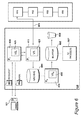
- FIG. 1 illustrates an environment in which the invention may be implemented.
- a number of clients 101 , 102 , 103 and 104 are connected to Internet 105 .
- Each of clients 101 to 104 is a device capable of connecting across a network to a service provider 110 .
- they may be desktop computers, laptops, mobile computing devices, or any other suitable computing device.
- they connect across Internet 105 , but they could be connecting to a local area network, a wide area network or some other type of network.
- Service provider 110 comprises a number of servers 111 , 112 , 113 and 114 . These all have access to the same data and respond to client requests in the same way, such that a request for data from any one of clients 101 to 104 can be routed to any one of servers 111 to 114 and be treated in exactly the same way.
- Servers 111 to 114 may be physically separate or may reside on one or more physical machines, and are connected by a local network 115 .
- the servers may be connected over any type of network, and would in fact be remote from each other. However, for performance reasons, it is preferable for the traffic manager and managed servers to be on a local network.
- the routing of client requests to the servers is performed by a traffic manager 120 .
- This receives requests over the Internet 105 from a client computer and uses load balancing algorithms to determine which server to send the request to.
- traffic manager 120 will connect to the selected server, say server 111 , and route the request.
- server 111 may hang, fail or return an error code.
- traffic manager 120 may bring such an event to the attention of an engineer, in current systems the high incoming request rate means that by the time the engineer is able to inspect the system, details of the malicious request may no longer be available.
- Server logs may comprise details of the request's originating IP address, but any opportunity to observe how the server responded to the request and the reason for failure will no longer be available.
- FIG. 2 shows traffic manager 120 . It comprises a processor provided in this example by CPU 201 , such as an Intel® Xeon® processor, 8 gigabytes of RAM 202 , and storage provided by a 1 terabyte hard disk drive 203 . A portion of storage on hard disk drive 203 is designated as virtual memory 204 .
- CPU 201 such as an Intel® Xeon® processor, 8 gigabytes of RAM 202 , and storage provided by a 1 terabyte hard disk drive 203 .
- a portion of storage on hard disk drive 203 is designated as virtual memory 204 .
- Instructions may be loaded from a CD-ROM 205 by a CD-ROM drive 206 , or alternatively they may be downloaded from a network via a network interface 207 .
- Network interface 207 also provides connectivity to the Internet 105 and to local network 115 , in order that traffic manager 120 may route requests between clients and the servers.
- an input device interface 208 which allows the connection of human interface devices such as display 209 , keyboard 210 and mouse 211 .
- FIG. 3 details CPU 201 . It contains four cores 301 , 302 , 303 and 304 , along with a memory controller 305 and a level two cache 306 .
- Core 301 includes a compute unit 307 and a level one cache 308 .
- the other cores are identical. Providing four cores in a single CPU allows up to four sets of instructions to be processed simultaneously by CPU 201 , thus increasing the speed and efficiency of traffic manager 120 .
- the CPU could have a different number of cores, or the processor could be provided by more than one CPU.
- more than one compute unit could be presented to an operating system on each core through the use of simultaneous multi-threading or similar.
- the level one caches of the cores and the level two cache 306 combine with RAM 202 and virtual memory 204 to provide memory for traffic manager 120 .
- the exact location of instructions and data within the memory will vary between embodiments, implementations and particular requirements at any specific time.
- FIG. 4 An abstraction layer diagram of traffic manager 120 is shown in FIG. 4 .
- On the first level are the hardware components detailed in FIGS. 2 and 3 .
- firmware 401 that receives instructions from a kernel 402 and converts them into machine code executable by the components.
- Kernel 402 manages allocation of memory to processes and the scheduling of process threads to CPU 201 . Kernel 402 allocates portions of memory to various processes under its control. A portion is allocated as shared memory, which is readable and writable by all processes. Some portions are readable and writable only by the kernel 402 itself, and others are only readable and writable by individual processes. Additionally, kernel 402 manages the flow of output data provided by the firmware 401 to processes.
- Process layer 403 comprises in this example five processes.
- Process 410 is a parent process that spawns child processes 411 , 412 , 413 and 414 .
- four processes 411 to 414 are spawned because there are four compute units available.
- each of the compute units may be running threads associated with one only of the processes 410 to 415 .
- Each of processes 410 to 414 includes a virtual server 420 to 424 for performing processing on requests.
- Kernel 402 dispatches requests received via network interface 207 to process 410 , whose virtual server 420 using a round robin scheduling algorithm to in turn dispatch the requests to any of processes 411 to 412 .
- Virtual server 421 in process 411 receives requests from process 410 , and performs request modification according to predefined rules. Upon completion of request modification, virtual server 421 runs a load balancing algorithm to select which of servers 111 to 114 to dispatch each request to. Requests are then routed by opening a connection to the selected server. The remaining processes 412 to 414 operate in a similar way.
- the virtual servers 421 to 424 monitor the connections they make to the servers and produce monitored connection data.
- traffic manager 120 implements the traffic management instructions using virtual servers running in separate processes, all of the processing occurs on the same physical apparatus. Additionally, all of the data, instructions and code used by the virtual servers responsible for processing and routing requests (who produce the monitored connection data) resides within the same memory as the rest of the operating system's kernel and additional processes in traffic manager 120 .
- any operations involving the copying or moving of monitored connection data do not require that the data itself is copied or moved between physical devices. Instead, any copying can be achieved by creating references to the monitored connection data's place in memory, and any moving can be achieved by marking the monitored connection data as belonging to different processes. This is therefore a much less computationally intensive task than in other systems, and allows the monitored connection data to be retained and used for analysis.
- the monitored connection data produced by virtual servers 421 to 424 is buffered by an additional virtual server 425 running in buffer process 415 .
- FIG. 5 details steps carried out by traffic manager 120 to route requests from clients 101 to 104 to servers 111 to 114 .
- traffic manager 120 is powered on and at step 502 a question is asked as to whether the traffic management instructions are installed. If this question is answered in the negative then at step 503 the instructions are installed, either from a computer-readable medium such as CD-ROM 205 or from a network such as the Internet 105 .
- Process 410 then carries out steps of establishing a network connection to network 115 at step 505 and inspecting the configuration of CPU 201 at step 506 .
- Process 410 then spawns the necessary number of child processes, which in this example is four, at step 507 .
- the number of processes is dependent on the number of compute units present in the CPU or CPUs on the traffic manager, so that if necessary each of the child processes could be run concurrently by CPU 201 .
- buffer process 415 is spawned that manages the buffering of monitored connection data.
- client requests are received and routed to the servers.
- the traffic manager then continues to route requests indefinitely until powered off for any reason at 510 .
- Parent process 410 is responsible for monitoring processes 411 to 415 , and if one of them crashes it spawns a new process to replace it.
- FIG. 6 illustrates the flow of requests and data between client 101 , traffic manager 120 and servers 111 to 114 .
- Client 101 sends a request 601 to service provider 110 for some data stored by each of servers 111 to 114 .
- the request is received by traffic manager 120 via its network interface 207 , and is dispatched by kernel 402 to parent process 410 .
- Virtual server 420 within parent process 410 makes a decision as to which child process 411 to 414 to send the request to for further processing.
- the chosen child process is child process 411 comprising virtual server 421 .
- Virtual server 421 processes request 601 , and runs a load balancing algorithm to assess which of servers 111 to 114 is best suited to service request 601 .
- the running of the algorithm results in server 111 being selected.
- Virtual server 421 proceeds to open a connection 603 to server 111 , and routes request 601 using connection 603 .
- the server responds by sending the requested data 602 back to virtual server 421 over connection 603 , where it is dispatched back to parent process 410 for sending to client 101 via network interface 207 .
- Buffer process 415 comprises virtual server 425 , which is responsible for maintaining a buffer 605 .
- Buffer 605 is a fixed width array that contains references to a finite number of the data structures in archive 604 , although any other type of data structure that is suitable for storing references may be used.
- garbage collection service 606 When new references are added to buffer 605 , old references are removed and garbage collected by a garbage collection service 606 .
- An external user interface process 607 is permitted to access buffer 605 , and provide an engineer with a view at any particular moment of the monitored connection data in archive 604 that is referenced by buffer 605 .
- the process of facilitating this functionality will be described further with reference to FIGS. 11 to 13 .
- FIG. 7 illustrates the process of archiving monitored connection data.
- virtual servers 421 to 424 archive the monitored connection data when a request has been serviced.
- virtual server 421 in child process 411 Upon opening connection 603 to server 111 and routing request 601 , virtual server 421 in child process 411 begins to monitor the progress of the servicing of request 601 . This results in monitored connection data being produced, which is written to a temporary file 701 in memory.
- temporary file 701 is a generic file to which a raw stream of data is written representing the monitored connection data.
- temporary file 701 may be a comma-separated value text file, which comprises elements of the monitored connection data delimited by commas.
- Monitored connection data in temporary file 701 comprises data relating to the individual connection, such as a unique identifier for the particular connection, the IP address of the requesting client, the IP address of the server, the length of time the connection was alive for, the size of the request, the data that was returned, and so on.
- monitored connection data in temporary file 701 will include data describing the cause of the error and how the server reacted. For example, if server 111 was servicing HTTP requests, then a request for a web page that does not exist on server 111 will result in a standard HTTP error code 504 being included within monitored connection data in temporary file 701 .
- monitored connection data in temporary file 701 would include data describing the error encountered by the server's operating system.
- virtual server 420 Upon the completion of servicing request 601 , virtual server 420 completes writing monitored connection data to temporary file 701 , and converts it into a data structure 702 .
- Data structure 702 structures the monitored connection data such that each element of data relating to the monitored connection has a key, whose value is the data.
- suitable data structure types include records, arrays, associative arrays or sets. The conversion of temporary file 701 into data structure 702 allows the quick searching for data, as the structure of data structure 702 is predictable and ordered.
- memory management services such as a virtual memory manager in kernel 402 and the physical memory register in RAM 202 , direct programs wishing to access data structure 702 to its location in the memory of traffic manager 120 .
- Steps carried out by virtual server 421 to archive monitored connection data during step 509 are shown in FIG. 8 .
- virtual server 421 receives a client request that has been dispatched to it by parent process 420 .
- the request is processed and a load balancing decision is made to decide which server to route the request to.
- virtual server 421 creates a connection to the chosen server at step 803 , and at step 804 the monitoring of the connection begins, producing monitored connection data which is written to temporary file 701 .
- the request is routed to the chosen server.
- the chosen server responds to virtual sever 421 by either sending the requested data, in which case the servicing of client request was successful, or by reporting an error code.
- virtual server 421 completes the writing of monitored connection data to temporary file 701 at step 807 , and at step 808 temporary file 701 is converted into data structure 702 .
- Data structure 702 is then marked as being a member of archive 604 at step 809 .
- FIG. 9 illustrates the buffering of data structures for access by an external user interface process.
- Buffer 605 is used to present a user of traffic manager 120 with a view of the most recently serviced connections using user interface process 607 , and to allow access to the monitored connection data inside the data structures for inspection of various metrics.
- reference 902 When a data structure 901 is marked as belonging to archive 604 , virtual server 425 running in buffer process 415 creates a reference 902 to it.
- Reference 902 only contains data indicating the location in memory of data structure 901 , i.e. it is a pointer. Thus, reference 902 is much smaller in size than data structure 901 , and does not require as many computation cycles to create or manipulate as creating a new copy in memory of data structure 901 .
- references that are currently in buffer 605 are marked as being members of buffer 605 . Additionally, in order to stop referenced data structures being moved or removed from memory, when they are referenced they are marked as buffered. This ensures that any process that is pointed to a portion of memory by a reference will find the correct data structure.
- buffer 605 is of fixed width, it can only contain a finite number of elements. Therefore, before reference 902 is marked as being a member of buffer 605 , an oldest reference 903 in buffer 605 is relinquished by being unmarked as being a member of buffer 605 , and the data structure it was referring to is unmarked as buffered.
- garbage collection service 606 will alert kernel 402 and any memory management services to the fact that the portion of memory allocated to oldest reference 903 is no longer in use.
- virtual server 425 marks reference 902 as being a member of buffer 605 . It then proceeds to also mark data structure 901 as buffered.
- buffer 605 will contain a reference to data structure 901 , which represents the most recently made connection to a server by any child process.
- buffer 605 is of a finite size, the size can be specified by a user. Thus, in some situations, a low request rate (say, 100 requests per second) is encountered and a buffer size of 10,000 connections would suffice. However, in other situations, the request rate is extremely high (say, 10,000 requests per second) and a much larger buffer is required in order to allow access to a reasonable length of time's worth of monitored connection data.
- the retention of references in buffer 605 is dependent upon attributes of the request whose data structure they point to.
- criteria are established to the effect that only references to data structures for requests having an HTTP header size of greater than 8 kilobytes (which is the maximum allowed by many web server systems) are retained in buffer 605 .
- the retention criteria could specify that the nth byte in the request is of a certain value. The selected byte could be one of particular interest; for example, it could monitor whether the SYN flag is set in a packet, and so only references are stored for completely new requests that have not been assigned a connection to a server.
- This selection of retention criteria is particularly useful when the stability of a cluster is usually very good, and it is only requests having certain characteristics that cause issues. It could also be useful if the incoming request rate was particularly high, say in the region of 1,000,000 incoming requests per second. In an embodiment, in which the incoming request rate fluctuates a great deal, then there is a threshold, say 1,000 requests per second, under which the buffer stores references for all requests, but over which retention criteria are invoked in order to keep potentially problematic requests accessible for a reasonable period of time.
- a number of named buffers are maintained, with the results of several retention criteria, such as those set out above, leading to references for different data structures being stored in different named buffers.
- An additional buffer is maintained as well, and stores references for data structures corresponding to requests or connections that meet certain criteria, i.e. they are of interest.
- the generic buffer has a high churn rate, but the additional buffer has a much lower churn rate as it is more likely that data structures containing interesting monitored connection data will need to be accessed for analysis over longer periods of time, say days are weeks rather than over the course of hours.
- Steps carried out by buffer process 415 to add a new reference to buffer 605 are shown in FIG. 10 .
- reference 902 is created by virtual server 425 that refers to new data structure 901 .
- oldest reference 903 in buffer 605 is unmarked as being a member of the buffer, and at step 1003 the data structure that it referred to is unmarked as buffered.
- garbage collection service 606 is able to reclaim the memory that was allocated to the oldest reference and the data structure.
- reference 902 is marked as being a member of buffer 605
- data structure 901 is marked as buffered.
- reference 902 will be unmarked as buffered along with the data structure it references, at which point garbage collection service 606 will allow other data to be written to the reference and data structure's respective memory positions.
- FIG. 11 illustrates the creation of a snapshot of buffer 605 .
- request rates may peak at around 100,000 requests for data per second. Due to the high rate of requests being processed by traffic manager 120 , the churn rate on even a large size connection buffer will be high.
- a snapshot of the state of the buffer is created.
- the snapshot of the buffer is simply a copy of the references contained in the buffer at the moment the snapshot is created, and thus will continue to remain static irrespective of the removal and addition of references to the buffer.
- the buffer only contains references whose data is small in size, and not copies of the data structures comprising large volumes of data, it is a much less computationally intensive task to snapshot the buffer in this form.
- buffer 605 the contents of buffer 605 are copied to a snapshot 1101 located in a newly allocated portion of memory.
- buffer 605 is frozen and is relabelled as snapshot 1101 , with an empty portion of memory then being allocated as buffer 605 .
- referenced data structures such as data structures 1102 , 1103 and 1104 in archive 604 (the data structures referenced by snapshot 1101 ) are marked as locked. Thus, for as long as the snapshot exists, the data structures being referenced are not able to be moved, altered or deleted.
- queries 1105 are executed by spawning a query process in traffic manager 120 for searching referenced data structures referred to by snapshot 1101 .
- Queries 1105 comprise statements of attributes of monitored connection data that a user wishes to filter the data structures for. For example, such query strings may instruct a query process to filter data structures by a specific IP address, or filter for any HTTP error code beginning with a “5”.
- snapshot 1101 needs to be retained for further analysis, the contents are copied to hard disk drive 203 , along with referenced data structures such as data structures 1102 , 1103 and 1104 for retrieval at a later time. This results in the creation of stored snapshots and stored data structures in a snapshot store 1106 on disk.
- Steps carried out by buffer process 415 to create a snapshot are shown in FIG. 12 .
- a user input is received that instructs traffic manager 120 to create a snapshot.
- the contents of the buffer are copied to a snapshot (or alternatively, the buffer is frozen and relabelled the snapshot, with the buffer being allocated an empty portion of memory).
- the referenced data structures referred to by the snapshot are marked as locked.
- a user input is received that instructs traffic manager 120 to run a query on the snapshot.
- the referenced data structures referred to by the snapshot are searched for data that matches the user-defined query terms.
- the details of data structures matching the terms of the query are returned to the user.
- Typical debugging systems rely on the repeatability of scenarios that cause software to crash.
- the ApacheTM web server is compatible with the free software tool GDB, which allows the debugging of instructions that cause the web server software to fail.
- tools such as GDB rely on the instruction being able to be fed back in to the web server whilst the GDB tool is running and can monitor the web server's response.
- GDB free software tool
- the apparatus of the present invention allows the recreation of the event that caused a server to encounter an error.
- the monitored connection data comprises enough details about the request (such as the virtual server that processed it, the server that serviced it, the route the connection took through the network and the details of the request itself) that a debugging process can be spawned within traffic manager 120 to recreate the request and the conditions that caused an error.
- FIG. 13 illustrates the debugging of a problem-causing request.
- a debugging process 1301 is spawned within traffic manager 120 , containing a virtual server 1302 .
- Debugging process 1301 locates and loads the monitored connection data from either a data structure in memory or a stored data structure on disk. The location will depend upon whether the snapshot the data structure belongs to is recent and is still in memory or was saved to disk and is being accessed at a later date.
- Debugging process 1301 proceeds to use the monitored connection data to reconstruct a request 1303 .
- the monitored connection data also indicates which virtual server processed the original request, and also which server serviced the request. In this case, virtual server 421 in child process 411 and server 111 were used. This results in debug code 1304 being produced detailing the historic attributes of request 1303 .
- Debug code 1304 also includes user-specified instructions regarding break points in the execution of the processing and servicing of request 1303 .
- debugging process 1301 dispatches request 1303 to child process 411 , along with debug code 1304 , where virtual server 421 processes and routes them to server 111 .
- a debug report 1305 is then produced at every specified break point, which allows the user to inspect the state of the connection at that moment, along with an opportunity to inspect the state of the entire system.
- FIG. 14 details steps carried out by a debugging process to access and debug a connection referred to by a snapshot.
- a user input is received that instructs traffic manager 120 to begin debugging a particular connection in a snapshot, and at step 1402 a debugging process is spawned within traffic manager 120 .
- the debugging process includes a virtual server that operates in the same way as virtual servers 421 to 424 .
- the snapshot is located in memory or on hard disk drive 203 , depending on whether it is being inspected immediately or has been retained on disk for further analysis.
- the monitored connection data stored in the referenced data structures is located in the snapshot at step 1403 , and at step 1404 the debugging process recreates the request from the monitored connection data.
- the debugging process ascertains which virtual server processed the request, and which server serviced the request.
- the debugging process dispatches the request to the virtual process that processed the request with an instruction to route it to the server found during step 1405 .
- the connection to the server is created, at step 1408 monitoring of the connection begins, and at step 1409 the request is routed.
- the user interface process 607 reports to the user the results of the debugging of connections.
- user input is received that results in the monitored connection data being modified prior to the debugging process recreating the request.
- modifications can include modifying or even removing certain fields in a request's HTTP header, changing data that was present in the connection stream, or even altering ancillary data such as the actual server that the connection was made to and which virtual server processed the request.
- the recreated connection can be made to specialised server infrastructure that is specifically installed for the purposes of debugging, and thus the debugging procedure does not interfere with primary infrastructure that is in the process of serving ongoing client requests.
Abstract
Description
Claims (20)
Applications Claiming Priority (2)
| Application Number | Priority Date | Filing Date | Title |
|---|---|---|---|
| GB1014367.5 | 2010-08-27 | ||
| GB1014367.5A GB2483111A (en) | 2010-08-27 | 2010-08-27 | Monitoring connections to servers and memory management |
Publications (2)
| Publication Number | Publication Date |
|---|---|
| US20120144026A1 US20120144026A1 (en) | 2012-06-07 |
| US8843620B2 true US8843620B2 (en) | 2014-09-23 |
Family
ID=43013391
Family Applications (1)
| Application Number | Title | Priority Date | Filing Date |
|---|---|---|---|
| US13/218,504 Active 2032-10-25 US8843620B2 (en) | 2010-08-27 | 2011-08-26 | Monitoring connections |
Country Status (3)
| Country | Link |
|---|---|
| US (1) | US8843620B2 (en) |
| EP (1) | EP2424190B1 (en) |
| GB (1) | GB2483111A (en) |
Cited By (1)
| Publication number | Priority date | Publication date | Assignee | Title |
|---|---|---|---|---|
| US20150248446A1 (en) * | 2006-03-14 | 2015-09-03 | Amazon Technologies, Inc. | Method and system for collecting and analyzing time-series data |
Families Citing this family (7)
| Publication number | Priority date | Publication date | Assignee | Title |
|---|---|---|---|---|
| KR20140098390A (en) * | 2013-01-31 | 2014-08-08 | 삼성전자주식회사 | Apparatus and method for detecting attack of network system |
| US8977746B2 (en) * | 2013-03-20 | 2015-03-10 | Watchguard Technologies, Inc. | Systems and methods for scalable network monitoring |
| CN103488733B (en) * | 2013-09-17 | 2017-10-27 | 新浪网技术(中国)有限公司 | A kind of method and device for importing data |
| US10165004B1 (en) | 2015-03-18 | 2018-12-25 | Cequence Security, Inc. | Passive detection of forged web browsers |
| US11418520B2 (en) * | 2015-06-15 | 2022-08-16 | Cequence Security, Inc. | Passive security analysis with inline active security device |
| US10931713B1 (en) | 2016-02-17 | 2021-02-23 | Cequence Security, Inc. | Passive detection of genuine web browsers based on security parameters |
| US10931686B1 (en) | 2017-02-01 | 2021-02-23 | Cequence Security, Inc. | Detection of automated requests using session identifiers |
Citations (13)
| Publication number | Priority date | Publication date | Assignee | Title |
|---|---|---|---|---|
| US20020042823A1 (en) | 1998-05-29 | 2002-04-11 | Debettencourt Jason | Web service |
| US20020062359A1 (en) * | 2000-10-03 | 2002-05-23 | Klopp Ana H. Von | HTTP transaction monitor with capacity to replay in debuggings session |
| US20020138618A1 (en) * | 2000-03-21 | 2002-09-26 | F5 Networks, Inc. | Simplified method for processing multiple connections from the same client |
| US6505248B1 (en) * | 1999-03-24 | 2003-01-07 | Gte Data Services Incorporated | Method and system for monitoring and dynamically reporting a status of a remote server |
| US20030069952A1 (en) | 1998-05-28 | 2003-04-10 | 3Com Corporation | Methods and apparatus for monitoring, collecting, storing, processing and using network traffic data of overlapping time periods |
| US20050015773A1 (en) * | 2003-05-20 | 2005-01-20 | International Business Machines Corporation | Monitoring operational data in data processing systems |
| WO2005050468A1 (en) | 2003-10-22 | 2005-06-02 | International Business Machines Corporation | Connection management method, system, and program product |
| US20060288171A1 (en) | 2005-06-20 | 2006-12-21 | Benjamin Tsien | Buffer allocation for split data messages |
| US20070294387A1 (en) * | 2003-02-08 | 2007-12-20 | Grex Games Limited | System Architecture for Load Balancing in Distributed Multi-User Application |
| US7383332B2 (en) * | 2002-04-08 | 2008-06-03 | International Business Machines Corporation | Method for problem determination in distributed enterprise applications |
| US20090019137A1 (en) * | 2007-07-10 | 2009-01-15 | Ragingwire Enterprise Solutions, Inc. | Method and remote system for creating a customized server infrastructure in real time |
| EP2161896A1 (en) | 2008-09-05 | 2010-03-10 | Zeus Technology Limited | Supplying data files to requesting stations |
| US20130054528A1 (en) * | 2011-08-31 | 2013-02-28 | Hitachi, Ltd. | Computer system and data access control method |
Family Cites Families (2)
| Publication number | Priority date | Publication date | Assignee | Title |
|---|---|---|---|---|
| US8140665B2 (en) * | 2005-08-19 | 2012-03-20 | Opnet Technologies, Inc. | Managing captured network traffic data |
| WO2008129641A1 (en) * | 2007-04-13 | 2008-10-30 | Fujitsu Limited | Capture device and capture method |
-
2010
- 2010-08-27 GB GB1014367.5A patent/GB2483111A/en not_active Withdrawn
-
2011
- 2011-08-19 EP EP11250733.0A patent/EP2424190B1/en active Active
- 2011-08-26 US US13/218,504 patent/US8843620B2/en active Active
Patent Citations (13)
| Publication number | Priority date | Publication date | Assignee | Title |
|---|---|---|---|---|
| US20030069952A1 (en) | 1998-05-28 | 2003-04-10 | 3Com Corporation | Methods and apparatus for monitoring, collecting, storing, processing and using network traffic data of overlapping time periods |
| US20020042823A1 (en) | 1998-05-29 | 2002-04-11 | Debettencourt Jason | Web service |
| US6505248B1 (en) * | 1999-03-24 | 2003-01-07 | Gte Data Services Incorporated | Method and system for monitoring and dynamically reporting a status of a remote server |
| US20020138618A1 (en) * | 2000-03-21 | 2002-09-26 | F5 Networks, Inc. | Simplified method for processing multiple connections from the same client |
| US20020062359A1 (en) * | 2000-10-03 | 2002-05-23 | Klopp Ana H. Von | HTTP transaction monitor with capacity to replay in debuggings session |
| US7383332B2 (en) * | 2002-04-08 | 2008-06-03 | International Business Machines Corporation | Method for problem determination in distributed enterprise applications |
| US20070294387A1 (en) * | 2003-02-08 | 2007-12-20 | Grex Games Limited | System Architecture for Load Balancing in Distributed Multi-User Application |
| US20050015773A1 (en) * | 2003-05-20 | 2005-01-20 | International Business Machines Corporation | Monitoring operational data in data processing systems |
| WO2005050468A1 (en) | 2003-10-22 | 2005-06-02 | International Business Machines Corporation | Connection management method, system, and program product |
| US20060288171A1 (en) | 2005-06-20 | 2006-12-21 | Benjamin Tsien | Buffer allocation for split data messages |
| US20090019137A1 (en) * | 2007-07-10 | 2009-01-15 | Ragingwire Enterprise Solutions, Inc. | Method and remote system for creating a customized server infrastructure in real time |
| EP2161896A1 (en) | 2008-09-05 | 2010-03-10 | Zeus Technology Limited | Supplying data files to requesting stations |
| US20130054528A1 (en) * | 2011-08-31 | 2013-02-28 | Hitachi, Ltd. | Computer system and data access control method |
Cited By (2)
| Publication number | Priority date | Publication date | Assignee | Title |
|---|---|---|---|---|
| US20150248446A1 (en) * | 2006-03-14 | 2015-09-03 | Amazon Technologies, Inc. | Method and system for collecting and analyzing time-series data |
| US9990385B2 (en) * | 2006-03-14 | 2018-06-05 | Amazon Technologies, Inc. | Method and system for collecting and analyzing time-series data |
Also Published As
| Publication number | Publication date |
|---|---|
| US20120144026A1 (en) | 2012-06-07 |
| EP2424190A1 (en) | 2012-02-29 |
| GB201014367D0 (en) | 2010-10-13 |
| EP2424190B1 (en) | 2019-03-06 |
| GB2483111A (en) | 2012-02-29 |
Similar Documents
| Publication | Publication Date | Title |
|---|---|---|
| US8843620B2 (en) | Monitoring connections | |
| US11645183B1 (en) | User interface for correlation of virtual machine information and storage information | |
| US9787706B1 (en) | Modular architecture for analysis database | |
| US10810074B2 (en) | Unified error monitoring, alerting, and debugging of distributed systems | |
| KR101925696B1 (en) | Managed service for acquisition, storage and consumption of large-scale data streams | |
| Ma et al. | {Kernel-Supported}{Cost-Effective} Audit Logging for Causality Tracking | |
| AU2015364688B2 (en) | Data stream processing language for analyzing instrumented software | |
| US20190220315A1 (en) | Dynamic Adjustment Of Application Resources In A Distributed Computing System | |
| US8527458B2 (en) | Logging framework for a data stream processing server | |
| US9911083B2 (en) | Automated defect and optimization discovery | |
| US20090235267A1 (en) | Consolidated display of resource performance trends | |
| US8996925B2 (en) | Managing error logs in a distributed network fabric | |
| US11323463B2 (en) | Generating data structures representing relationships among entities of a high-scale network infrastructure | |
| US8904063B1 (en) | Ordered kernel queue for multipathing events | |
| JP2012053903A (en) | Distributed retrieval method, architecture, system and software | |
| US11036608B2 (en) | Identifying differences in resource usage across different versions of a software application | |
| US10657099B1 (en) | Systems and methods for transformation and analysis of logfile data | |
| US20210133054A1 (en) | Prioritized transfer of failure event log data | |
| KR102025210B1 (en) | Queue monitoring and visualization | |
| CN113760847A (en) | Log data processing method, device, equipment and storage medium | |
| US20210224102A1 (en) | Characterizing operation of software applications having large number of components | |
| JP2004178336A (en) | System and method for managing operation, management computer, computer to be monitored, and program | |
| WO2016100534A1 (en) | Data stream processing language for analyzing instrumented software | |
| US20240069948A1 (en) | Mapping common paths for applications | |
| US20210073062A1 (en) | Performing Root Cause Analysis in a Multi-Role Application |
Legal Events
| Date | Code | Title | Description |
|---|---|---|---|
| AS | Assignment |
Owner name: RIVERBED TECHNOLOGY, INC., CALIFORNIA Free format text: ASSIGNMENT OF ASSIGNORS INTEREST;ASSIGNORS:CONLON, DECLAN SEAN;HARRIS, EUAN DAVID;SIGNING DATES FROM 20120125 TO 20120207;REEL/FRAME:027693/0388 |
|
| AS | Assignment |
Owner name: MORGAN STANLEY & CO. LLC, MARYLAND Free format text: SECURITY AGREEMENT;ASSIGNORS:RIVERBED TECHNOLOGY, INC.;OPNET TECHNOLOGIES, INC.;REEL/FRAME:029646/0060 Effective date: 20121218 |
|
| FEPP | Fee payment procedure |
Free format text: PAYOR NUMBER ASSIGNED (ORIGINAL EVENT CODE: ASPN); ENTITY STATUS OF PATENT OWNER: LARGE ENTITY |
|
| AS | Assignment |
Owner name: RIVERBED TECHNOLOGY, INC., CALIFORNIA Free format text: RELEASE OF PATENT SECURITY INTEREST;ASSIGNOR:MORGAN STANLEY & CO. LLC, AS COLLATERAL AGENT;REEL/FRAME:032113/0425 Effective date: 20131220 |
|
| AS | Assignment |
Owner name: JPMORGAN CHASE BANK, N.A., AS ADMINISTRATIVE AGENT, NEW YORK Free format text: PATENT SECURITY AGREEMENT;ASSIGNOR:RIVERBED TECHNOLOGY, INC.;REEL/FRAME:032421/0162 Effective date: 20131220 Owner name: JPMORGAN CHASE BANK, N.A., AS ADMINISTRATIVE AGENT Free format text: PATENT SECURITY AGREEMENT;ASSIGNOR:RIVERBED TECHNOLOGY, INC.;REEL/FRAME:032421/0162 Effective date: 20131220 |
|
| STCF | Information on status: patent grant |
Free format text: PATENTED CASE |
|
| AS | Assignment |
Owner name: RIVERBED TECHNOLOGY, INC., CALIFORNIA Free format text: RELEASE BY SECURED PARTY;ASSIGNOR:JPMORGAN CHASE BANK, N.A., AS COLLATERAL AGENT;REEL/FRAME:035078/0354 Effective date: 20150303 |
|
| AS | Assignment |
Owner name: BROCADE COMMUNICATIONS SYSTEMS, INC., CALIFORNIA Free format text: ASSIGNMENT OF ASSIGNORS INTEREST;ASSIGNOR:RIVERBED TECHNOLOGY, INC.;REEL/FRAME:035097/0776 Effective date: 20150303 |
|
| AS | Assignment |
Owner name: MORGAN STANLEY SENIOR FUNDING, INC., AS COLLATERAL AGENT, NEW YORK Free format text: SECURITY INTEREST;ASSIGNOR:RIVERBED TECHNOLOGY, INC.;REEL/FRAME:035561/0363 Effective date: 20150424 Owner name: MORGAN STANLEY SENIOR FUNDING, INC., AS COLLATERAL Free format text: SECURITY INTEREST;ASSIGNOR:RIVERBED TECHNOLOGY, INC.;REEL/FRAME:035561/0363 Effective date: 20150424 |
|
| AS | Assignment |
Owner name: RIVERBED TECHNOLOGY, INC., CALIFORNIA Free format text: PARTIAL RELEASE OF SECURITY INTEREST IN PATENTS RECORDED AT R/F 035561/0363;ASSIGNOR:MORGAN STANLEY SENIOR FUNDING, INC., AS COLLATERAL AGENT;REEL/FRAME:041298/0876 Effective date: 20170106 |
|
| AS | Assignment |
Owner name: PULSE SECURE, LLC, CALIFORNIA Free format text: ASSIGNMENT OF ASSIGNORS INTEREST;ASSIGNOR:BROCADE COMMUNICATION SYSTEMS, INC.;REEL/FRAME:043604/0172 Effective date: 20170731 |
|
| MAFP | Maintenance fee payment |
Free format text: PAYMENT OF MAINTENANCE FEE, 4TH YEAR, LARGE ENTITY (ORIGINAL EVENT CODE: M1551) Year of fee payment: 4 |
|
| AS | Assignment |
Owner name: KKR LOAN ADMINISTRATION SERVICES LLC, AS COLLATERAL AGENT, NEW YORK Free format text: SECURITY INTEREST;ASSIGNOR:PULSE SECURE, LLC;REEL/FRAME:053638/0220 Effective date: 20200824 |
|
| AS | Assignment |
Owner name: PULSE SECURE, LLC, CALIFORNIA Free format text: RELEASE OF SECURITY INTEREST : RECORDED AT REEL/FRAME - 053638-0220;ASSIGNOR:KKR LOAN ADMINISTRATION SERVICES LLC;REEL/FRAME:054559/0368 Effective date: 20201201 |
|
| AS | Assignment |
Owner name: MORGAN STANLEY SENIOR FUNDING, INC., AS COLLATERAL AGENT, MARYLAND Free format text: SECURITY INTEREST;ASSIGNORS:CELLSEC, INC.;PULSE SECURE, LLC;IVANTI, INC.;AND OTHERS;REEL/FRAME:054665/0062 Effective date: 20201201 Owner name: BANK OF AMERICA, N.A., AS COLLATERAL AGENT, ILLINOIS Free format text: SECURITY INTEREST;ASSIGNORS:CELLSEC, INC.;PULSE SECURE, LLC;INVANTI, INC.;AND OTHERS;REEL/FRAME:054665/0873 Effective date: 20201201 |
|
| MAFP | Maintenance fee payment |
Free format text: PAYMENT OF MAINTENANCE FEE, 8TH YEAR, LARGE ENTITY (ORIGINAL EVENT CODE: M1552); ENTITY STATUS OF PATENT OWNER: LARGE ENTITY Year of fee payment: 8 |