US8840969B1 - Method and apparatus for adjusting the relative movement between flocking fibers and flocked objects - Google Patents
Method and apparatus for adjusting the relative movement between flocking fibers and flocked objects Download PDFInfo
- Publication number
- US8840969B1 US8840969B1 US13/788,095 US201313788095A US8840969B1 US 8840969 B1 US8840969 B1 US 8840969B1 US 201313788095 A US201313788095 A US 201313788095A US 8840969 B1 US8840969 B1 US 8840969B1
- Authority
- US
- United States
- Prior art keywords
- fibers
- flocking
- machine direction
- longitudinal
- speed
- Prior art date
- Legal status (The legal status is an assumption and is not a legal conclusion. Google has not performed a legal analysis and makes no representation as to the accuracy of the status listed.)
- Active
Links
Images

Classifications
-
- B—PERFORMING OPERATIONS; TRANSPORTING
- B05—SPRAYING OR ATOMISING IN GENERAL; APPLYING FLUENT MATERIALS TO SURFACES, IN GENERAL
- B05B—SPRAYING APPARATUS; ATOMISING APPARATUS; NOZZLES
- B05B5/00—Electrostatic spraying apparatus; Spraying apparatus with means for charging the spray electrically; Apparatus for spraying liquids or other fluent materials by other electric means
- B05B5/08—Plant for applying liquids or other fluent materials to objects
- B05B5/081—Plant for applying liquids or other fluent materials to objects specially adapted for treating particulate materials
-
- B—PERFORMING OPERATIONS; TRANSPORTING
- B05—SPRAYING OR ATOMISING IN GENERAL; APPLYING FLUENT MATERIALS TO SURFACES, IN GENERAL
- B05B—SPRAYING APPARATUS; ATOMISING APPARATUS; NOZZLES
- B05B5/00—Electrostatic spraying apparatus; Spraying apparatus with means for charging the spray electrically; Apparatus for spraying liquids or other fluent materials by other electric means
- B05B5/08—Plant for applying liquids or other fluent materials to objects
- B05B5/082—Plant for applying liquids or other fluent materials to objects characterised by means for supporting, holding or conveying the objects
- B05B5/084—Plant for applying liquids or other fluent materials to objects characterised by means for supporting, holding or conveying the objects the objects lying on, or being supported above conveying means, e.g. conveyor belts
-
- B—PERFORMING OPERATIONS; TRANSPORTING
- B05—SPRAYING OR ATOMISING IN GENERAL; APPLYING FLUENT MATERIALS TO SURFACES, IN GENERAL
- B05B—SPRAYING APPARATUS; ATOMISING APPARATUS; NOZZLES
- B05B5/00—Electrostatic spraying apparatus; Spraying apparatus with means for charging the spray electrically; Apparatus for spraying liquids or other fluent materials by other electric means
- B05B5/16—Arrangements for supplying liquids or other fluent material
- B05B5/1683—Arrangements for supplying liquids or other fluent material specially adapted for particulate materials
-
- B—PERFORMING OPERATIONS; TRANSPORTING
- B05—SPRAYING OR ATOMISING IN GENERAL; APPLYING FLUENT MATERIALS TO SURFACES, IN GENERAL
- B05C—APPARATUS FOR APPLYING FLUENT MATERIALS TO SURFACES, IN GENERAL
- B05C19/00—Apparatus specially adapted for applying particulate materials to surfaces
- B05C19/001—Flocking
- B05C19/002—Electrostatic flocking
-
- B—PERFORMING OPERATIONS; TRANSPORTING
- B05—SPRAYING OR ATOMISING IN GENERAL; APPLYING FLUENT MATERIALS TO SURFACES, IN GENERAL
- B05D—PROCESSES FOR APPLYING FLUENT MATERIALS TO SURFACES, IN GENERAL
- B05D1/00—Processes for applying liquids or other fluent materials
- B05D1/02—Processes for applying liquids or other fluent materials performed by spraying
- B05D1/12—Applying particulate materials
- B05D1/14—Flocking
Definitions
- a moving object is flocked with loose fibers by a flocking machine (such as Maagflock FF 380-430 flat flocker from Maag Flockmaschinen GmbH, Kusterdingen, Germany)
- a flocking machine such as Maagflock FF 380-430 flat flocker from Maag Flockmaschinen GmbH, Kusterdingen, Germany
- the electrostatic flocking process uses electrostatic forces between the fibers themselves and between the fibers and the object. Some time is required for the attraction/repulsion forces to affect the position and placement of the fibers evenly into the object. As a result of the horizontal speed difference between the object and the fibers, there is less of a possibility for the fibers to penetrate properly and evenly into the object, hence the flocking quality is ruined.
- the fibers hit the object while the object is moving so the front end of the fibres is pulled forward, in the machine direction.
- the fibers are anchored in a slanted position, covering a larger object surface area preventing more fibers to be anchored.
- the result is a poor flocking density, coverage, and quality.
- This invention discloses a method and apparatus to overcome the shortcomings of the current technology by providing a way to control and adjust the relative longitudinal speed between flocked fibers and a flocked object, therefore substantially reducing the relative longitudinal movement between the object and the fibers hitting the object. This results in better flocking quality at a higher speed of the flocked objects, and may also increase manufacturing speed.
- the disclosed apparatus comprises a device which acquires the horizontal movement of the flocked fibers along the machine direction.
- the fibers after leaving the flocking machine and on their way towards the flocked object, are moving horizontally and vertically simultaneously.
- the difference in longitudinal speed between the object and the fibers is minimized, allowing for a greater chance of the fibers to be anchored into the object in a more even and vertical manner.
- the method and apparatus of the present application allows for the adjustment of the horizontal, machine direction ‘speed component’ of the fibers, thus allowing for the adjustment of the relative longitudinal speed between the object and the fibers.
- This ability to adjust the horizontal speed component of the fibers improves flocking process quality and increases production speed and output.
- the term “longitudinal speed” refers to the horizontal component of the speed between the fibers and the object to be flocked.
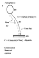
- FIG. 1 shows a trajectory of fibers in the air of a prior art flocking machine
- FIG. 2 shows a trajectory of fibers in the air of a flocking machine in accordance with the present application
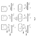
- FIG. 3 shows a trajectory of fibers and an object along the flocking process in a prior art apparatus for flocking fibers
- FIG. 4 shows a trajectory of fibers and an object along the flocking process in an apparatus for flocking fibers in accordance with the present application.
- FIGS. 1 and 3 show a prior art flocking machine 100 and an apparatus and method for flocking fibers.
- fibers 102 move solely along a vertical path 103 to an object to be flocked 101 .
- V 2 represents the vertical speed component (in vector terms) of the fibers 102 , which is created by gravity and by the electrostatic attraction between the fibers and the object.
- the vertical speed V 2 of the fibers in both the prior art system and the disclosed system is substantially equal.
- V 3 represents the longitudinal speed of the fibers, which is typically zero in prior art systems ( FIGS. 1 and 3 ).
- fibers 202 move along a curved or arcuate path 203 which includes both a vertical V 2 and a horizontal V 3 speed component of the fibers from a flocking machine 200 to an object to be flocked 201 .
- V 2 is the vertical speed component (in vector terms) of the fibers created by gravity and by the electrostatic attraction between the fibers and the object.
- the vertical speed of the fibers in this system is substantially equal to the vertical speed in the prior art system.
- V 3 represents the longitudinal speed component of the fibers which is controlled and adjustable in the disclosed system.
- FIGS. 3 and 4 show the angle in which the fibers are embedded in the object in both systems.
- V 1 represents the longitudinal speed of the object, which may be a mold.
- T 1 is the time when the fibers leave the flocking machine 200
- T 2 represents the time where the fibers are on their way to the object to be flocked 201
- T 3 represents the time when the fibers reach the flocked object.
- an apparatus 200 comprises a device which allows for horizontal movement of flocked fibers, along the machine direction.
- the fibers 202 after they leave the flocking machine 200 and on their way towards the flocked object 201 , move horizontally (forward) and vertically (downward), at the same time, which creates the fibers' path 203 . Therefore, the path 203 is curved or arcuate as shown in FIG. 2 .
- the apparatus 200 is a moving mesh.
- the mesh moves at a speed of V 4 in the horizontal direction, in the machine direction, to closely match the longitudinal speed V 1 of the object 201 , and the speed of the fibers may be controlled and adjustable to be similar, slightly faster, or slightly slower than the longitudinal speed V 3 of the object.
- the mesh when the flocking is performed on a continuous moving object or objects which are very close to each other, such as a conveyor belt or a group of objects moving closely together, the mesh may be designed as a rotating mesh carousel, moving on a horizontal, cross machine direction axis, and the rotating mesh rotates continuously.
- the mesh when there are enough gaps between the objects to be flocked, the mesh may be designed to move forward, in the machine direction, during the flocking stage, and backwards to its original position during the phases between each flocking session, in intervals.
- the horizontal speed V 3 of the fibers, at their starting point on their way down from the flocking machine to the object may be set to be faster than the object horizontal speed to compensate for the reduction of the longitudinal speed V 3 of the fibers, created by air resistance. This results in better horizontal speed matching when the fibers hit the object.
- the apparatus may comprise a monitoring system to provide real time monitoring of the longitudinal speed of the fibers along the flocking process.
- the monitoring system may include any suitable vision system, including an industrial vision system.
- the industrial vision system may comprise ultra-violet light, a stroboscopic device, or any other suitable tools to assist viewing.
- an industrial vision software may be employed to adjust the longitudinal speed V 3 of the fibers 202 according to desired results in a pre-set mode or in real time.
- the fibers 202 are provided with inertia and movement in the longitudinal, machine direction by blowing air in the flocking machine 200 .
- the fibers 202 are provided with inertia and movement in the longitudinal, machine direction by blowing air in the flocking area.
- the fibers 202 are provided with inertia and movement in the longitudinal, machine direction by blowing gas in the flocking machine 200 .
- the fibers 202 are provided with inertia and movement in the longitudinal, machine direction by blowing gas in the flocking area.
- the fibers 202 are provided with inertia and movement in the longitudinal, machine direction by blowing by electrostatic or magnetic power, or by a combination of both.
Landscapes
- Application Of Or Painting With Fluid Materials (AREA)
- Electrostatic Spraying Apparatus (AREA)
- Treatment Of Fiber Materials (AREA)
Abstract
Description
Claims (6)
Priority Applications (9)
| Application Number | Priority Date | Filing Date | Title |
|---|---|---|---|
| US13/788,095 US8840969B1 (en) | 2013-03-07 | 2013-03-07 | Method and apparatus for adjusting the relative movement between flocking fibers and flocked objects |
| CA2904130A CA2904130C (en) | 2013-03-07 | 2014-03-05 | Method and apparatus for adjusting the relative movement between flocking fibers and flocked objects |
| MX2015011835A MX380195B (en) | 2013-03-07 | 2014-03-05 | METHOD AND APPARATUS FOR ADJUSTING RELATIVE MOTION BETWEEN FLOCKED FIBERS AND FLOCKED OBJECTS. |
| CN201480013508.3A CN105121026B (en) | 2013-03-07 | 2014-03-05 | Method and apparatus for regulating relative movement between flocking fibers and flocking objects |
| BR112015021816A BR112015021816A2 (en) | 2013-03-07 | 2014-03-05 | method and apparatus for adjusting relative motion between flocking fibers and flocked objects |
| PCT/IB2014/000544 WO2014135971A1 (en) | 2013-03-07 | 2014-03-05 | Method and apparatus for adjusting the relative movement between flocking fibers and flocked objects |
| EP14720244.4A EP2964391A1 (en) | 2013-03-07 | 2014-03-05 | Method and apparatus for adjusting the relative movement between flocking fibers and flocked objects |
| JP2015560798A JP6486281B2 (en) | 2013-03-07 | 2014-03-05 | Method and apparatus for adjusting the relative movement of a flocked fiber and the object to be flocked |
| IL241217A IL241217B (en) | 2013-03-07 | 2015-09-06 | Method and apparatus for adjusting the relative movement between flocking fibers and flocked objects |
Applications Claiming Priority (1)
| Application Number | Priority Date | Filing Date | Title |
|---|---|---|---|
| US13/788,095 US8840969B1 (en) | 2013-03-07 | 2013-03-07 | Method and apparatus for adjusting the relative movement between flocking fibers and flocked objects |
Publications (2)
| Publication Number | Publication Date |
|---|---|
| US20140255596A1 US20140255596A1 (en) | 2014-09-11 |
| US8840969B1 true US8840969B1 (en) | 2014-09-23 |
Family
ID=50624885
Family Applications (1)
| Application Number | Title | Priority Date | Filing Date |
|---|---|---|---|
| US13/788,095 Active US8840969B1 (en) | 2013-03-07 | 2013-03-07 | Method and apparatus for adjusting the relative movement between flocking fibers and flocked objects |
Country Status (9)
| Country | Link |
|---|---|
| US (1) | US8840969B1 (en) |
| EP (1) | EP2964391A1 (en) |
| JP (1) | JP6486281B2 (en) |
| CN (1) | CN105121026B (en) |
| BR (1) | BR112015021816A2 (en) |
| CA (1) | CA2904130C (en) |
| IL (1) | IL241217B (en) |
| MX (1) | MX380195B (en) |
| WO (1) | WO2014135971A1 (en) |
Cited By (2)
| Publication number | Priority date | Publication date | Assignee | Title |
|---|---|---|---|---|
| WO2017212337A1 (en) | 2016-06-08 | 2017-12-14 | Tamicare Ltd. | Liquid polymer sprayed sheet with fused layers and variable ratio of polymers droplets and entrapped bubbles |
| WO2024249336A1 (en) | 2023-05-26 | 2024-12-05 | Nike Innovate C.V. | Three dimensional molds for liquid spray deposition, and methods and systems for creating articles of apparel using same |
Families Citing this family (1)
| Publication number | Priority date | Publication date | Assignee | Title |
|---|---|---|---|---|
| WO2016051270A1 (en) * | 2014-10-01 | 2016-04-07 | Tamicare Ltd. | Apparatus to produce 3d curved flocked articles |
Citations (3)
| Publication number | Priority date | Publication date | Assignee | Title |
|---|---|---|---|---|
| GB1098035A (en) | 1964-05-05 | 1968-01-03 | Dunlop Co Ltd | Improvements in flock-coating of articles |
| US3591403A (en) * | 1968-12-05 | 1971-07-06 | Bigelow Sanford Inc | Electrostatic flocking |
| US3678894A (en) * | 1969-12-24 | 1972-07-25 | Indev Inc | Flocking |
Family Cites Families (3)
| Publication number | Priority date | Publication date | Assignee | Title |
|---|---|---|---|---|
| JPH05115831A (en) * | 1991-10-24 | 1993-05-14 | Nordson Kk | Transfer type coating method for powder and granular material. |
| CN101293240B (en) * | 2007-04-27 | 2012-05-23 | 张裕兴 | Velvet falling apparatus for flocking machine |
| CN202460952U (en) * | 2011-04-08 | 2012-10-03 | 如皋市天元服饰印业有限公司 | Movable static flocking machine |
-
2013
- 2013-03-07 US US13/788,095 patent/US8840969B1/en active Active
-
2014
- 2014-03-05 CA CA2904130A patent/CA2904130C/en active Active
- 2014-03-05 WO PCT/IB2014/000544 patent/WO2014135971A1/en not_active Ceased
- 2014-03-05 BR BR112015021816A patent/BR112015021816A2/en active Search and Examination
- 2014-03-05 MX MX2015011835A patent/MX380195B/en unknown
- 2014-03-05 JP JP2015560798A patent/JP6486281B2/en not_active Expired - Fee Related
- 2014-03-05 CN CN201480013508.3A patent/CN105121026B/en not_active Expired - Fee Related
- 2014-03-05 EP EP14720244.4A patent/EP2964391A1/en not_active Withdrawn
-
2015
- 2015-09-06 IL IL241217A patent/IL241217B/en active IP Right Grant
Patent Citations (3)
| Publication number | Priority date | Publication date | Assignee | Title |
|---|---|---|---|---|
| GB1098035A (en) | 1964-05-05 | 1968-01-03 | Dunlop Co Ltd | Improvements in flock-coating of articles |
| US3591403A (en) * | 1968-12-05 | 1971-07-06 | Bigelow Sanford Inc | Electrostatic flocking |
| US3678894A (en) * | 1969-12-24 | 1972-07-25 | Indev Inc | Flocking |
Cited By (2)
| Publication number | Priority date | Publication date | Assignee | Title |
|---|---|---|---|---|
| WO2017212337A1 (en) | 2016-06-08 | 2017-12-14 | Tamicare Ltd. | Liquid polymer sprayed sheet with fused layers and variable ratio of polymers droplets and entrapped bubbles |
| WO2024249336A1 (en) | 2023-05-26 | 2024-12-05 | Nike Innovate C.V. | Three dimensional molds for liquid spray deposition, and methods and systems for creating articles of apparel using same |
Also Published As
| Publication number | Publication date |
|---|---|
| CA2904130C (en) | 2022-01-04 |
| US20140255596A1 (en) | 2014-09-11 |
| CN105121026A (en) | 2015-12-02 |
| WO2014135971A1 (en) | 2014-09-12 |
| EP2964391A1 (en) | 2016-01-13 |
| IL241217B (en) | 2020-08-31 |
| BR112015021816A2 (en) | 2017-07-18 |
| JP6486281B2 (en) | 2019-03-20 |
| JP2016515041A (en) | 2016-05-26 |
| IL241217A0 (en) | 2015-11-30 |
| MX2015011835A (en) | 2016-05-05 |
| CN105121026B (en) | 2018-01-23 |
| MX380195B (en) | 2025-03-12 |
| CA2904130A1 (en) | 2014-09-12 |
Similar Documents
| Publication | Publication Date | Title |
|---|---|---|
| US12049051B2 (en) | Method for forming three-dimensional structures with different material portions | |
| US8840969B1 (en) | Method and apparatus for adjusting the relative movement between flocking fibers and flocked objects | |
| US11358340B2 (en) | System and method for forming three-dimensional structures | |
| US9776362B2 (en) | Additive manufacturing system and additive manufacturing method | |
| MX2015010835A (en) | Method and apparatus for changing carriage speed on a closed-loop track. | |
| EP4309536A3 (en) | Three-dimensional printing along a curved surface | |
| EP2639105A8 (en) | Vehicular light distribution control system and vehicular light distribution control method | |
| EP4234244A3 (en) | Airflow control for additive manufacturing | |
| EP4711883A3 (en) | Systems and methods for uav flight control | |
| MX359829B (en) | Method and apparatus for controlling balanced vehicle. | |
| EP3551946A4 (en) | AIR CONDITIONER, ITS CONTROL METHOD, AND A METHOD FOR CONTROLLING THE SAME | |
| MX2022006643A (en) | Method and device for producing a decorative wall- or floor panel. | |
| EP2592491A3 (en) | Image forming apparatus and image forming method | |
| EP3598012A4 (en) | METHOD FOR CONTROLLING AIR CONDITIONER AIR DEFLECTORS AND ASSOCIATED AIR CONDITIONER | |
| EP2377641A3 (en) | Method and apparatus for Manufacturing a Component | |
| EP4219417A3 (en) | Apparatus and process for producing fiber from igneous rock | |
| MY185928A (en) | Tire pattern determination device, vehicle type determination apparatus, tire pattern determination method, and program | |
| CN106002441A (en) | Conveying mechanism for automatic perpendicularity of screws | |
| EP4530067A3 (en) | Systems and methods for additive manufacturing | |
| GB2452917A (en) | Curved Blast Furnace Chute | |
| CN204353071U (en) | A kind of base material fixed length zero tension force dip coating apparatus | |
| CN204723665U (en) | Magnetic control device for fitness equipment | |
| JP2022508677A (en) | Equipment for powder deposition mechanism in additive manufacturing process | |
| PH12021552222A1 (en) | Method for adjusting wind direction of blower, and vehicle equipped with blower | |
| CA3148935A1 (en) | Method for transferring cargo from a cargo receiving portion of a vehicle, and vehicle for carrying out said method |
Legal Events
| Date | Code | Title | Description |
|---|---|---|---|
| AS | Assignment |
Owner name: TAMICARE LTD, UNITED KINGDOM Free format text: ASSIGNMENT OF ASSIGNORS INTEREST;ASSIGNOR:GILOH, EHUD;REEL/FRAME:030040/0183 Effective date: 20130313 |
|
| STCF | Information on status: patent grant |
Free format text: PATENTED CASE |
|
| MAFP | Maintenance fee payment |
Free format text: PAYMENT OF MAINTENANCE FEE, 4TH YR, SMALL ENTITY (ORIGINAL EVENT CODE: M2551) Year of fee payment: 4 |
|
| FEPP | Fee payment procedure |
Free format text: MAINTENANCE FEE REMINDER MAILED (ORIGINAL EVENT CODE: REM.); ENTITY STATUS OF PATENT OWNER: SMALL ENTITY |
|
| FEPP | Fee payment procedure |
Free format text: 7.5 YR SURCHARGE - LATE PMT W/IN 6 MO, SMALL ENTITY (ORIGINAL EVENT CODE: M2555); ENTITY STATUS OF PATENT OWNER: SMALL ENTITY |
|
| MAFP | Maintenance fee payment |
Free format text: PAYMENT OF MAINTENANCE FEE, 8TH YR, SMALL ENTITY (ORIGINAL EVENT CODE: M2552); ENTITY STATUS OF PATENT OWNER: SMALL ENTITY Year of fee payment: 8 |