US8835043B2 - Battery pack - Google Patents
Battery pack Download PDFInfo
- Publication number
- US8835043B2 US8835043B2 US13/219,091 US201113219091A US8835043B2 US 8835043 B2 US8835043 B2 US 8835043B2 US 201113219091 A US201113219091 A US 201113219091A US 8835043 B2 US8835043 B2 US 8835043B2
- Authority
- US
- United States
- Prior art keywords
- frame
- battery pack
- rib
- frame parts
- cell
- Prior art date
- Legal status (The legal status is an assumption and is not a legal conclusion. Google has not performed a legal analysis and makes no representation as to the accuracy of the status listed.)
- Active, expires
Links
Images


Classifications
-
- H01M2/0212—
-
- H—ELECTRICITY
- H01—ELECTRIC ELEMENTS
- H01M—PROCESSES OR MEANS, e.g. BATTERIES, FOR THE DIRECT CONVERSION OF CHEMICAL ENERGY INTO ELECTRICAL ENERGY
- H01M50/00—Constructional details or processes of manufacture of the non-active parts of electrochemical cells other than fuel cells, e.g. hybrid cells
- H01M50/20—Mountings; Secondary casings or frames; Racks, modules or packs; Suspension devices; Shock absorbers; Transport or carrying devices; Holders
- H01M50/204—Racks, modules or packs for multiple batteries or multiple cells
-
- H—ELECTRICITY
- H01—ELECTRIC ELEMENTS
- H01M—PROCESSES OR MEANS, e.g. BATTERIES, FOR THE DIRECT CONVERSION OF CHEMICAL ENERGY INTO ELECTRICAL ENERGY
- H01M10/00—Secondary cells; Manufacture thereof
- H01M10/42—Methods or arrangements for servicing or maintenance of secondary cells or secondary half-cells
- H01M10/425—Structural combination with electronic components, e.g. electronic circuits integrated to the outside of the casing
-
- H—ELECTRICITY
- H01—ELECTRIC ELEMENTS
- H01M—PROCESSES OR MEANS, e.g. BATTERIES, FOR THE DIRECT CONVERSION OF CHEMICAL ENERGY INTO ELECTRICAL ENERGY
- H01M50/00—Constructional details or processes of manufacture of the non-active parts of electrochemical cells other than fuel cells, e.g. hybrid cells
- H01M50/20—Mountings; Secondary casings or frames; Racks, modules or packs; Suspension devices; Shock absorbers; Transport or carrying devices; Holders
- H01M50/271—Lids or covers for the racks or secondary casings
- H01M50/273—Lids or covers for the racks or secondary casings characterised by the material
-
- H—ELECTRICITY
- H01—ELECTRIC ELEMENTS
- H01M—PROCESSES OR MEANS, e.g. BATTERIES, FOR THE DIRECT CONVERSION OF CHEMICAL ENERGY INTO ELECTRICAL ENERGY
- H01M50/00—Constructional details or processes of manufacture of the non-active parts of electrochemical cells other than fuel cells, e.g. hybrid cells
- H01M50/20—Mountings; Secondary casings or frames; Racks, modules or packs; Suspension devices; Shock absorbers; Transport or carrying devices; Holders
- H01M50/289—Mountings; Secondary casings or frames; Racks, modules or packs; Suspension devices; Shock absorbers; Transport or carrying devices; Holders characterised by spacing elements or positioning means within frames, racks or packs
- H01M50/291—Mountings; Secondary casings or frames; Racks, modules or packs; Suspension devices; Shock absorbers; Transport or carrying devices; Holders characterised by spacing elements or positioning means within frames, racks or packs characterised by their shape
-
- H—ELECTRICITY
- H01—ELECTRIC ELEMENTS
- H01M—PROCESSES OR MEANS, e.g. BATTERIES, FOR THE DIRECT CONVERSION OF CHEMICAL ENERGY INTO ELECTRICAL ENERGY
- H01M50/00—Constructional details or processes of manufacture of the non-active parts of electrochemical cells other than fuel cells, e.g. hybrid cells
- H01M50/20—Mountings; Secondary casings or frames; Racks, modules or packs; Suspension devices; Shock absorbers; Transport or carrying devices; Holders
- H01M50/289—Mountings; Secondary casings or frames; Racks, modules or packs; Suspension devices; Shock absorbers; Transport or carrying devices; Holders characterised by spacing elements or positioning means within frames, racks or packs
- H01M50/293—Mountings; Secondary casings or frames; Racks, modules or packs; Suspension devices; Shock absorbers; Transport or carrying devices; Holders characterised by spacing elements or positioning means within frames, racks or packs characterised by the material
-
- H—ELECTRICITY
- H01—ELECTRIC ELEMENTS
- H01M—PROCESSES OR MEANS, e.g. BATTERIES, FOR THE DIRECT CONVERSION OF CHEMICAL ENERGY INTO ELECTRICAL ENERGY
- H01M50/00—Constructional details or processes of manufacture of the non-active parts of electrochemical cells other than fuel cells, e.g. hybrid cells
- H01M50/50—Current conducting connections for cells or batteries
- H01M50/543—Terminals
- H01M50/547—Terminals characterised by the disposition of the terminals on the cells
- H01M50/55—Terminals characterised by the disposition of the terminals on the cells on the same side of the cell
-
- H—ELECTRICITY
- H01—ELECTRIC ELEMENTS
- H01M—PROCESSES OR MEANS, e.g. BATTERIES, FOR THE DIRECT CONVERSION OF CHEMICAL ENERGY INTO ELECTRICAL ENERGY
- H01M50/00—Constructional details or processes of manufacture of the non-active parts of electrochemical cells other than fuel cells, e.g. hybrid cells
- H01M50/50—Current conducting connections for cells or batteries
- H01M50/543—Terminals
- H01M50/552—Terminals characterised by their shape
- H01M50/553—Terminals adapted for prismatic, pouch or rectangular cells
- H01M50/557—Plate-shaped terminals
-
- H—ELECTRICITY
- H01—ELECTRIC ELEMENTS
- H01M—PROCESSES OR MEANS, e.g. BATTERIES, FOR THE DIRECT CONVERSION OF CHEMICAL ENERGY INTO ELECTRICAL ENERGY
- H01M50/00—Constructional details or processes of manufacture of the non-active parts of electrochemical cells other than fuel cells, e.g. hybrid cells
- H01M50/50—Current conducting connections for cells or batteries
- H01M50/572—Means for preventing undesired use or discharge
- H01M50/584—Means for preventing undesired use or discharge for preventing incorrect connections inside or outside the batteries
- H01M50/586—Means for preventing undesired use or discharge for preventing incorrect connections inside or outside the batteries inside the batteries, e.g. incorrect connections of electrodes
-
- H—ELECTRICITY
- H01—ELECTRIC ELEMENTS
- H01M—PROCESSES OR MEANS, e.g. BATTERIES, FOR THE DIRECT CONVERSION OF CHEMICAL ENERGY INTO ELECTRICAL ENERGY
- H01M50/00—Constructional details or processes of manufacture of the non-active parts of electrochemical cells other than fuel cells, e.g. hybrid cells
- H01M50/50—Current conducting connections for cells or batteries
- H01M50/572—Means for preventing undesired use or discharge
- H01M50/584—Means for preventing undesired use or discharge for preventing incorrect connections inside or outside the batteries
- H01M50/59—Means for preventing undesired use or discharge for preventing incorrect connections inside or outside the batteries characterised by the protection means
- H01M50/595—Tapes
-
- Y—GENERAL TAGGING OF NEW TECHNOLOGICAL DEVELOPMENTS; GENERAL TAGGING OF CROSS-SECTIONAL TECHNOLOGIES SPANNING OVER SEVERAL SECTIONS OF THE IPC; TECHNICAL SUBJECTS COVERED BY FORMER USPC CROSS-REFERENCE ART COLLECTIONS [XRACs] AND DIGESTS
- Y02—TECHNOLOGIES OR APPLICATIONS FOR MITIGATION OR ADAPTATION AGAINST CLIMATE CHANGE
- Y02E—REDUCTION OF GREENHOUSE GAS [GHG] EMISSIONS, RELATED TO ENERGY GENERATION, TRANSMISSION OR DISTRIBUTION
- Y02E60/00—Enabling technologies; Technologies with a potential or indirect contribution to GHG emissions mitigation
- Y02E60/10—Energy storage using batteries
Definitions
- Embodiments of the present invention relate to a battery pack.
- a battery pack in general, includes a bare cell having an electrode assembly housed in a case, and a cover frame surrounding edges of side surfaces of the bare cell.
- the cover frame is required to be tightly coupled to the side surfaces of the bare cell and easily formable to be manufactured in high yield.
- Embodiments of the present invention provide a battery pack having a cover frame configured to be tightly coupled to side surfaces of a bare cell and easily formable to be manufactured in high yield.
- a battery pack including a bare cell, and a cover frame formed to surround top, bottom and opposing side surfaces of the bare cell, wherein the cover frame includes a rib formed only at lengthwise portions corresponding to opposing short side surfaces of the bare cell, and the rib protrude inwardly with respect to the cover frame.
- the rib may be formed at one end of the cover frame in a thickness direction, and a support portion may be formed at the other end of the cover frame in the thickness direction to protrude inwardly with respect to the cover frame.
- the support portion may be formed at a region other than a region where the rib is formed.
- the rib may cover a portion of a top surface of the bare cell, and the support portion may cover a portion of a bottom surface of the bare cell.
- the cover frame may include a first frame surrounding the top surface of the bare cell, a second frame surrounding the bottom surface of the bare cell and formed to face the first frame, and third and fourth frames surrounding short side surfaces of the bare cell and connecting one and the other ends of the first and second frames, respectively.
- the ribs may be formed in the third frame and the fourth frame and may be located at the distance from the first frame and the second frame.
- the battery pack may further include a rib formed in the second frame.
- the rib formed in the second frame may be located at the same distance from the one and the other ends of the second frame.
- One and the other ends of the support portion formed in the second frame may be connected to one ends of the support portions formed in the third and fourth frames, respectively.
- the ribs may be formed in the third frame and the fourth frame and may be located to be opposite to each other in view of the location of the distance from the first frame and the second frame.
- the battery pack may further include a rib formed in the second frame.
- the rib formed in the second frame may be located at the same distance from the one and the other ends of the second frame.
- One and the other ends of the support portion formed in the second frame may be connected to one ends of the support portions formed in the third and fourth frames, respectively.
- the cover frame may be made of an elastic material.
- the cover frame can be easily formed, thereby reducing the molding cost and improving the yield.
- FIG. 1 is a perspective view of a completed battery pack according to an embodiment of the present invention
- FIG. 2 is an exploded perspective view of a polymer cell in the battery pack shown in FIG. 1 ;
- FIG. 3A is a perspective view of a cover frame in the battery pack shown in FIG. 1
- FIG. 3B is a plan view of the cover frame shown in FIG. 3A ;
- FIG. 4A is a perspective view of a cover frame in a battery pack according to another embodiment of the present invention
- FIGS. 4B and 4C are alternative plan views of the cover frame shown in FIG. 4A .
- FIG. 1 is a perspective view of a completed battery pack according to an embodiment of the present invention
- FIG. 2 is an exploded perspective view of a polymer cell in the battery pack shown in FIG. 1 .
- the battery pack 100 includes a bare cell 10 , and a cover frame 20 surrounding top, bottom and opposing side surfaces of the bare cell 10 .
- the bare cell 10 includes an electrode assembly 1 and a case 11 housing the electrode assembly 10 .
- the electrode assembly 1 includes a positive electrode plate 2 having a positive electrode active material coated on its both surfaces, a negative electrode plate 4 having a negative electrode active material coated on its both surfaces, and a separator 3 interposed between the positive electrode plate 2 and the negative electrode plate 4 .
- a positive electrode tab 5 protruding a predetermined length and functioning as a positive electrode is attached to the positive electrode plate 2 .
- a negative electrode tab 6 protruding a predetermined length and functioning as a negative electrode is attached to the negative electrode plate 4 .
- An insulation tape 7 may further be provided in the positive electrode tab 5 and the negative electrode tab 6 to insulate each of the positive electrode tab 5 and the negative electrode tab 6 from the case 11 , respectively.
- the positive electrode tab 5 and the negative electrode tab 6 are drawn out to the outside through one side surface of the case 11 and are electrically connected to a protection circuit module (PCM) (not shown), respectively.
- PCM protection circuit module
- the case 11 is folded at the center of a layer forming the case 11 to then be divided into a lower case 12 and an upper case 13 .
- the lower case 12 has a receiving section 12 a formed by a pressing process to receive the electrode assembly 1 .
- the electrode assembly 1 is received in the receiving section 12 a and the lower case 12 is covered by the upper case 13 , followed by thermally welding edges of the receiving section 12 a , thereby completing the bare cell 10 .
- a surface of the bare cell 10 from which the electrode tabs 5 and 6 extend is referred to as a top surface, and a surface opposite to and facing the top surface is referred to as a bottom surface.
- a surface connecting one short side of the top surface to one short side of the bottom surface is referred to as a first short side surface
- a surface connecting the other short side of the top surface to the other short side of the bottom surface is referred to as a second short side surface.
- a surface connecting one long side of the top surface to one long side of the bottom surface is referred to as a first long side surface
- a surface, formed by upper case 13 , connecting the other long side of the top surface to the other long side of the bottom surface is referred to as a second long side surface.
- FIG. 3A is a perspective view of a cover frame in the battery pack shown in FIG. 1
- FIG. 3B is a plan view of the cover frame shown in FIG. 3A .
- the cover frame 20 includes a first frame 21 , a second frame 22 , a third frame 23 and a fourth frame 24 surrounding the top surface (from which the electrode tabs 5 and 6 extend), bottom surface and opposing short side surfaces of the bare cell 10 .
- the bare cell 10 is received in a cell receiving section 20 a surrounded by the first to fourth frames 21 , 22 , 23 and 24 .
- the cover frame 20 may further include a PCM (protection circuit module) receiving section 20 b adjacent to and separated from the cell receiving section 20 a by first frame 21 .
- the cover frame 20 may be made of an elastic material such as rubber.
- the present invention does not limit the material of the cover frame 20 to rubber, and any elastic material that is somewhat deformable can be used.
- the first frame 21 includes a first support portion 21 a ( FIG. 3B ) formed at a thicknesswise bottom end (edge) and tab receiving grooves 21 b ( FIG. 3A ) formed at a thicknesswise top end (edge).
- the first support portion 21 a is formed along at least a lengthwise a portion of the first frame 21 and extends from the thicknesswise bottom end of the first frame 21 toward the inside of the cover frame 20 , that is, toward the cell receiving section 20 a .
- the first support portion 21 a supports the first long side surface of the bare cell 10 accommodated inside the cell receiving section 20 a of the cover frame 20 .
- the first support portion 21 a is preferably formed from a lengthwise end of the first frame 21 to the other lengthwise end of the first frame 21 .
- the tab receiving grooves 21 b are formed at locations corresponding to the positive electrode tab 5 and the negative electrode tab 6 of the bare cell 10 accommodated in the cell receiving section 20 a . Therefore, the positive electrode tab 5 and the negative electrode tab 6 are drawn out toward the PCM receiving section 20 b through the tab receiving grooves 21 b , respectively, for electrical connection to the PCM (not shown) accommodated in the PCM receiving section 20 b.
- the second frame 22 includes a second support portion 22 a formed at a thicknesswise bottom end and a first rib 22 b formed at a thicknesswise top end.
- the second support portion 22 a is formed along at least a lengthwise portion of the second frame 22 and extends from the thicknesswise bottom end of the second frame 22 toward the cell receiving section 20 a .
- the second support portion 22 a supports the first long side surface of the bare cell 10 accommodated inside the cell receiving section 20 a of the cover frame 20 .
- the second support portion 22 a is preferably formed from a lengthwise end of the second frame 22 to the other lengthwise end of the second frame 22 .
- the first rib 22 b is formed along at least a lengthwise portion of the second frame 22 and extends from the thicknesswise top end of the second frame 22 toward the cell receiving section 20 a .
- the first rib 22 b supports the second long side surface of the bare cell 10 accommodated inside the cell receiving section 20 a of the cover frame 20 .
- the configuration in which the first rib 22 b is formed in the second frame 22 provides for a superb fixing effect particularly in a wide, thin battery pack having an increased long side surface of the bare cell 10 .
- first rib 22 b is preferably formed at a central portion of the top end of the second frame 22 , except that the second support portion 22 a may not be formed at a region corresponding to a region where a first rib 22 b , which will later be described, is formed.
- the second support portion 22 a is for the purpose of stably fixing the bare cell 10 accommodated in the cell receiving section 20 a of the cover frame 20 .
- the second support portion 22 a and the first rib 22 b are preferably formed so as not to overlap each other. That is to say, the second support portion 22 a is preferably not formed in an area of the lengthwise region of the second frame 22 corresponding to a region where the first rib 22 b is formed. This simplifies a molding structure, thereby facilitating fabrication of the cover frame 20 by injection molding and improving the yield of the battery pack 100 .
- the third frame 23 includes a third support portion 23 a formed at a thicknesswise bottom end and a second rib 23 b formed at a thicknesswise top end.
- the third support portion 23 a is formed along at least a lengthwise portion of the third frame 23 and extends from the thicknesswise bottom end of the third frame 23 toward the cell receiving section 20 a .
- the third support portion 23 a supports the first long side surface of the bare cell 10 accommodated inside the cell receiving section 20 a of the cover frame 20 .
- the third support portion 23 a is preferably formed from a lengthwise end of the third frame 23 to the other lengthwise end of the third frame 23 , except that the third support portion 23 a may not be formed at a region corresponding to a region where a second rib 23 b, which will later be described, is formed.
- one end of the third support portion 23 a is preferably connected to one end of the first support portion 21 a and the other end the third support portion 23 a is preferably connected to one end of the second support portion 22 a, which is for the purpose of increasing the supporting capacity of the support portions 21 a, 22 a and 23 a.
- the second rib 23 b is formed along at least a lengthwise portion of the third frame 23 and extends from the thicknesswise top end of the third frame 23 toward the cell receiving section 20 a .
- the second rib 23 b supports the second long side surface of the bare cell 10 accommodated inside the cell receiving section 20 a of the cover frame 20 .
- the second rib 23 b is preferably formed at a central portion of the top end of the third frame 23 . This is for the purpose of stably fixing the bare cell 10 accommodated in the cell receiving section 20 a of the cover frame 20 while facilitating insertion of the bare cell 10 into the cell receiving section 20 a of the cover frame 20 .
- the third support portion 23 a and the second rib 23 b are preferably formed so as not to overlap each other. That is to say, the third support portion 23 a may not be formed in an area of the lengthwise region of the third frame 23 corresponding to a region where the second rib 23 b is formed. Thus, fabrication of the cover frame 20 by injection molding is facilitated, thereby improving the yield of the battery pack 100 .
- the second rib 23 b is preferably shorter than the third support portion 23 a in a lengthwise direction of the third frame 23 . This is for the purpose of facilitating insertion of the bare cell 10 into the cell receiving section 20 a from the top portion of the cover frame 20 . That is to say, in order to insert the bare cell 10 into the cell receiving section 20 a , it is necessary for the second rib 23 b to elastically deform upwardly. Therefore, if the second rib 23 b is formed to be longer than the third support portion 23 a , it is not easy to insert the bare cell 10 into a region between the second rib 23 b and the third support portion 23 a.
- the fourth frame 24 includes a fourth support portion 24 a formed at a thicknesswise bottom end and a third rib 24 b formed at a thicknesswise top end.
- the fourth support portion 24 a is formed along at least a lengthwise portion of the fourth frame 24 and extends from the thicknesswise bottom end of the fourth frame 24 toward the cell receiving section 20 a .
- the fourth support portion 24 a supports the first long side surface of the bare cell 10 accommodated inside the cell receiving section 20 a of the cover frame 20 .
- the fourth support portion 24 a is preferably formed from a lengthwise end of the fourth frame 24 to the other lengthwise end of the fourth frame 24 , except that the fourth support portion 24 a may not be formed at a region corresponding to a region where a third rib 24 b , which will later be described, is formed.
- one end of the fourth support portion 24 a is preferably connected to one end of the first support portion 21 a and the other end the fourth support portion 24 a is preferably connected to one end of the second support portion 22 a , which is for the purpose of increasing the supporting capacity of the support portions 21 a , 22 a and 24 a.
- the third rib 24 b is formed along at least a lengthwise portion of the fourth frame 24 and extends from the thicknesswise top end of the fourth frame 24 toward the cell receiving section 20 a .
- the third rib 24 b supports the second long side surface of the bare cell 10 accommodated inside the cell receiving section 20 a of the cover frame 20 .
- the second rib 24 b is preferably formed at a central portion of the fourth frame 24 . This is for the purpose of stably fixing the bare cell 10 accommodated in the cell receiving section 20 a of the cover frame 20 while facilitating insertion of the bare cell 10 into the cell receiving section 20 a of the cover frame 20 .
- the fourth support portion 24 a and the third rib 24 b are preferably formed so as not to overlap each other. That is to say, the fourth support portion 24 a is preferably not formed in an area of the lengthwise region of the fourth frame 24 corresponding to a region where the third rib 24 b is formed. This facilitates fabrication of the cover frame 20 by injection molding, thereby improving the yield of the battery pack 100 .
- the third rib 24 b is preferably shorter than the fourth support portion 24 a in a lengthwise direction of the fourth frame 24 . This is for the purpose of facilitating insertion of the bare cell 10 into the cell receiving section 20 a from the top portion of the cover frame 20 . That is to say, in order to insert the bare cell 10 into the cell receiving section 20 a , it is necessary for the third rib 24 b to elastically deform upwardly. Therefore, if the third rib 24 b is formed to be longer than the fourth support portion 24 a , it is not easy to insert the bare cell 10 into a region between the third rib 24 b and the fourth support portion 24 a.
- each support section 22 a , 23 a and 24 a includes a gap therein formed at a central region of second, third and fourth frames 22 , 23 and 24 corresponding to a region where each the ribs 22 b , 23 b and 24 b are formed.
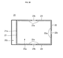
- FIG. 4A is a perspective view of a cover frame in a battery pack according to another embodiment of the present invention
- FIGS. 4B and 4C are alternative plan views of the cover frame shown in FIG. 4A .
- the cover frame 30 of the battery pack includes a first frame 31 , a second frame 32 a third frame 33 and a fourth frame 34 surrounding the top surface, the bottom surface and opposing side surfaces of the bare cell 10 .
- the bare cell 10 is received in a cell receiving section 30 a surrounded by the first to fourth frames 31 , 32 , 33 and 34 .
- the cover frame 30 may further include a PCM receiving section 30 b opposite to, and separated from, the cell receiving section 30 a by the first frame 31 .
- the first frame 31 includes a first support portion 31 a formed at a thicknesswise bottom end (edge) and tab receiving grooves 31 b formed at a thicknesswise top end (edge).
- the second frame 32 includes a second support portion 32 a formed at a thicknesswise bottom end and a first rib 32 b formed at a thicknesswise top end.
- the third frame 33 includes a third support portion 33 a formed at a thicknesswise bottom end and a second rib 33 b formed at a thicknesswise top end.
- the fourth frame 34 includes a fourth support portion 34 a formed at a thicknesswise bottom end and a third rib 34 b formed at a thicknesswise top end.
- the cover frame 30 of the battery pack according to the embodiment of the present invention is substantially the same as the cover frame 20 of the battery pack 100 , except for locations where the second rib 33 b and the third rib 34 b are formed, and corresponding where regions of the third support portion 33 a and the fourth support portion 34 a are not formed. Therefore, the cover frame 30 of the battery pack according to the embodiment of the present invention will be described with regard to the third support portion 33 a , the second rib 33 b , the fourth support portion 34 a and the third rib 34 b , and repeated explanations of the other components will not be given.
- the second rib 33 b may be formed at a location closer to the first frame 31 from a central portion of the third frame 33 .
- the third rib 34 b may be formed at a location closer to the second frame 32 from a central portion of the fourth frame 34 .
- the third support portion 33 a and the fourth support portion 34 a may not be formed at corresponding locations where the second rib 33 b and the third rib 34 b are formed. That is to say, when the cover frame 30 is viewed downwardly from the top, the third support portion 33 a and the second rib 33 b are preferably formed so as not to overlap each other, and the fourth support portion 34 a and the third rib 3 bb are preferably formed so as not to overlap each other.
- the second rib 33 b may be formed at a location closer to the second frame 32 from a central portion of the third frame 33 .
- the third rib 34 b may be formed at a location closer to the first frame 31 from a central portion of the fourth frame 34 .
- the third support portion 33 a and the fourth support portion 34 a may not be formed at corresponding locations where the second rib 33 b and the third rib 34 b are formed.
- the third support portion 33 a and the second rib 33 b are preferably formed so as not to overlap each other, and the fourth support portion 34 a and the third rib 3 bb are preferably formed so as not to overlap each other.
- each support section 32 a , 33 a and 34 a includes a gap therein formed at a region corresponding to a region where each the ribs 32 b , 33 b and 34 b are formed.
Landscapes
- Chemical & Material Sciences (AREA)
- Chemical Kinetics & Catalysis (AREA)
- Electrochemistry (AREA)
- General Chemical & Material Sciences (AREA)
- Engineering & Computer Science (AREA)
- Microelectronics & Electronic Packaging (AREA)
- Manufacturing & Machinery (AREA)
- Battery Mounting, Suspending (AREA)
Abstract
Description
Claims (14)
Applications Claiming Priority (2)
| Application Number | Priority Date | Filing Date | Title |
|---|---|---|---|
| KR10-2011-0011869 | 2011-02-10 | ||
| KR1020110011869A KR20120091837A (en) | 2011-02-10 | 2011-02-10 | Battery pack |
Publications (2)
| Publication Number | Publication Date |
|---|---|
| US20120208046A1 US20120208046A1 (en) | 2012-08-16 |
| US8835043B2 true US8835043B2 (en) | 2014-09-16 |
Family
ID=46637129
Family Applications (1)
| Application Number | Title | Priority Date | Filing Date |
|---|---|---|---|
| US13/219,091 Active 2031-12-04 US8835043B2 (en) | 2011-02-10 | 2011-08-26 | Battery pack |
Country Status (2)
| Country | Link |
|---|---|
| US (1) | US8835043B2 (en) |
| KR (1) | KR20120091837A (en) |
Families Citing this family (8)
| Publication number | Priority date | Publication date | Assignee | Title |
|---|---|---|---|---|
| US9608245B2 (en) | 2014-09-30 | 2017-03-28 | Johnson Controls Technology Company | System for providing structural integrity of a battery module |
| USD830964S1 (en) * | 2016-09-06 | 2018-10-16 | Apple Inc. | Battery for an electronic device |
| USD831025S1 (en) | 2017-08-10 | 2018-10-16 | Apple Inc. | Housing module for an electronic device |
| USD894119S1 (en) * | 2018-07-12 | 2020-08-25 | Getac Technology Corporation | Battery for portable electronic device |
| USD910545S1 (en) | 2018-08-23 | 2021-02-16 | Apple Inc. | Battery for an electronic device |
| USD949780S1 (en) | 2018-09-04 | 2022-04-26 | Apple Inc. | Battery for an electronic device |
| USD929317S1 (en) | 2019-11-22 | 2021-08-31 | Apple Inc. | Battery for an electronic device |
| USD929318S1 (en) | 2019-11-22 | 2021-08-31 | Apple Inc. | Battery for an electronic device |
Citations (7)
| Publication number | Priority date | Publication date | Assignee | Title |
|---|---|---|---|---|
| US5298347A (en) | 1992-09-14 | 1994-03-29 | Motorola, Inc. | Battery pack |
| JP2007073203A (en) | 2005-09-02 | 2007-03-22 | Sanyo Electric Co Ltd | Battery pack |
| KR20070102149A (en) | 2006-04-14 | 2007-10-18 | 주식회사 프론 | Battery housing frame |
| KR20080058965A (en) | 2006-12-23 | 2008-06-26 | 주식회사 엘지화학 | Battery pack case made of metal |
| US20090111018A1 (en) | 2007-10-30 | 2009-04-30 | Samsung Sdi Co., Ltd. | Battery pack |
| US7887949B2 (en) | 2005-04-26 | 2011-02-15 | Samsung Sdi Co., Ltd. | Polymer battery pack and method of manufacturing the same |
| US7910243B2 (en) | 2007-03-28 | 2011-03-22 | Samsung Sdi Co., Ltd. | Polymer battery pack |
-
2011
- 2011-02-10 KR KR1020110011869A patent/KR20120091837A/en not_active Ceased
- 2011-08-26 US US13/219,091 patent/US8835043B2/en active Active
Patent Citations (8)
| Publication number | Priority date | Publication date | Assignee | Title |
|---|---|---|---|---|
| US5298347A (en) | 1992-09-14 | 1994-03-29 | Motorola, Inc. | Battery pack |
| US7887949B2 (en) | 2005-04-26 | 2011-02-15 | Samsung Sdi Co., Ltd. | Polymer battery pack and method of manufacturing the same |
| JP2007073203A (en) | 2005-09-02 | 2007-03-22 | Sanyo Electric Co Ltd | Battery pack |
| KR20070102149A (en) | 2006-04-14 | 2007-10-18 | 주식회사 프론 | Battery housing frame |
| KR20080058965A (en) | 2006-12-23 | 2008-06-26 | 주식회사 엘지화학 | Battery pack case made of metal |
| US7910243B2 (en) | 2007-03-28 | 2011-03-22 | Samsung Sdi Co., Ltd. | Polymer battery pack |
| US20090111018A1 (en) | 2007-10-30 | 2009-04-30 | Samsung Sdi Co., Ltd. | Battery pack |
| KR20090043917A (en) | 2007-10-30 | 2009-05-07 | 삼성에스디아이 주식회사 | Battery pack |
Non-Patent Citations (2)
| Title |
|---|
| Korean Notice of Allowance issued on Dec. 30, 2013 in connection with Korean Patent Application No. 10-2013-0050131 which also claims Korean Patent Application No. 2011-0011869 as its priority document and Request for Entry of the Accompanying Office Action attached herewith. |
| Korean Office Action issued by KIPO on Jul. 20, 2012 in connection with Korean Patent Application No. 10-2011-0011869 and Request for Entry attached herewith. |
Also Published As
| Publication number | Publication date |
|---|---|
| KR20120091837A (en) | 2012-08-20 |
| US20120208046A1 (en) | 2012-08-16 |
Similar Documents
| Publication | Publication Date | Title |
|---|---|---|
| US8835043B2 (en) | Battery pack | |
| JP7128287B2 (en) | Battery module having structure with improved energy density, battery pack including the same, and automobile | |
| KR101223567B1 (en) | Battery module | |
| US8597822B2 (en) | Impact resistant battery pack | |
| US9793704B2 (en) | Secondary battery pack | |
| KR101754613B1 (en) | Rechargeable battery | |
| US9899638B2 (en) | Rechargeable battery | |
| US9905835B2 (en) | Secondary battery pack | |
| US10236476B2 (en) | Flexible electrochemical device including electrode assembly | |
| KR20190071454A (en) | Battery Module Having Bus bar Assembly | |
| US20110091747A1 (en) | Battery assembly | |
| JP5166462B2 (en) | Battery pack | |
| US20150064543A1 (en) | Battery module | |
| US20100124674A1 (en) | Battery pack | |
| KR101234242B1 (en) | Battery Pack | |
| CA2910915C (en) | Insulator and fuel cell device | |
| KR20170021130A (en) | Battery module having holder | |
| KR101057578B1 (en) | Polymer battery pack | |
| KR102082868B1 (en) | Battery Pack | |
| KR101075902B1 (en) | Battery Pack Case Having Resiliently Flexible Connecting Member | |
| US20150064504A1 (en) | Battery module having connecting tab | |
| US10333115B2 (en) | Tray for curved surface-structured battery cell | |
| KR100813812B1 (en) | Battery pack with fastening grooves formed in the frame member | |
| KR101351722B1 (en) | Battery pack | |
| KR20170027547A (en) | Cell module for secondary battery pack and assembly method for the same |
Legal Events
| Date | Code | Title | Description |
|---|---|---|---|
| AS | Assignment |
Owner name: SAMSUNG SDI CO., LTD., A CORPORATION CHARTERED IN Free format text: ASSIGNMENT OF ASSIGNORS INTEREST;ASSIGNOR:KOH, SEOK;REEL/FRAME:027189/0403 Effective date: 20110825 Owner name: SAMSUNG SDI CO., LTD., A CORPORATIONCHARTERED IN A Free format text: ASSIGNMENT OF ASSIGNORS INTEREST;ASSIGNOR:KOH, SEOK;REEL/FRAME:027189/0403 Effective date: 20110825 |
|
| FEPP | Fee payment procedure |
Free format text: PAYOR NUMBER ASSIGNED (ORIGINAL EVENT CODE: ASPN); ENTITY STATUS OF PATENT OWNER: LARGE ENTITY |
|
| STCF | Information on status: patent grant |
Free format text: PATENTED CASE |
|
| MAFP | Maintenance fee payment |
Free format text: PAYMENT OF MAINTENANCE FEE, 4TH YEAR, LARGE ENTITY (ORIGINAL EVENT CODE: M1551) Year of fee payment: 4 |
|
| MAFP | Maintenance fee payment |
Free format text: PAYMENT OF MAINTENANCE FEE, 8TH YEAR, LARGE ENTITY (ORIGINAL EVENT CODE: M1552); ENTITY STATUS OF PATENT OWNER: LARGE ENTITY Year of fee payment: 8 |