US883418A - Swinging door. - Google Patents
Swinging door. Download PDFInfo
- Publication number
- US883418A US883418A US38850907A US1907388509A US883418A US 883418 A US883418 A US 883418A US 38850907 A US38850907 A US 38850907A US 1907388509 A US1907388509 A US 1907388509A US 883418 A US883418 A US 883418A
- Authority
- US
- United States
- Prior art keywords
- door
- casing
- pivots
- bolt
- bolts
- Prior art date
- Legal status (The legal status is an assumption and is not a legal conclusion. Google has not performed a legal analysis and makes no representation as to the accuracy of the status listed.)
- Expired - Lifetime
Links
- 238000010276 construction Methods 0.000 description 2
- 238000006073 displacement reaction Methods 0.000 description 1
- 239000002184 metal Substances 0.000 description 1
Images


Classifications
-
- E—FIXED CONSTRUCTIONS
- E05—LOCKS; KEYS; WINDOW OR DOOR FITTINGS; SAFES
- E05D—HINGES OR SUSPENSION DEVICES FOR DOORS, WINDOWS OR WINGS
- E05D15/00—Suspension arrangements for wings
- E05D15/48—Suspension arrangements for wings allowing alternative movements
- E05D15/50—Suspension arrangements for wings allowing alternative movements for opening at either of two opposite edges
- E05D15/505—Suspension arrangements for wings allowing alternative movements for opening at either of two opposite edges by radial separation of the hinge parts at the hinge axis
Definitions
- N m ww w 1u naRRls Flrzns ca., vusnmcfan. n. c.
- the present invention pertains to doors and has for its object to provide a construction by means of which the door can be opened either from the left or right side to yanswer special requirements of the place where it is applied, and to afford greater convenience in manipulating the same.
- the door 1 is transversely grooved at its upper and lower ends, each groove 2 terminating at both ends in deeper notches or eX- cavations 3.
- the latter serve each to hold the casing 4 of metal and of rectangular cross section which fits therein and is rigidly secured to the door as at 5.
- the longitudinal walls of said casing are removable (see Fig. 4) to allow of an access thereto.
- a vertical piece or bolt 10 is loosely and slidably borne, which piece isy provided with a lateral cam shaped groove 11 and which is adapted to project outward from the casing through an aperture 12 therein.
- the outer end of said bolt is formed to a blade 13 having slightly curved surfaces 14 (Fig. 4).
- a horizontal sliding finger 16 is provided which with its reduced forward end 17 (Fig. 3a) is adapted to constantly engage the cam shaped groove 1 1 and by the forward movement of which the bolt is forced forward.
- the cam shaped finger 16 will be forced rearward.
- the slide 8 and the cam shaped finger 16 in one casing are connected with the finger 16 and the slide 8 respectively in the casing that lies horizontally opposite to the first, so that when the vertical bolt 10 is moved inwards the same will force the finger 16 rearwards, which by means of the rod 18 will operate the slide 8 in the opposite casing forcing the same forward into the space between .the inner end or the bolt 10 and the inner surface of the casing, thereby locking the bolt in position, i. c. preventing it from moving inward. ln a similar way bolt 10 will be locked in position when bolt 10 is moved inward by the operation of 'linger 16, rod 19 and slide 8.
- This mechanism consists of a cylindrical casing 24 in which a pivot 25 is rotatively borne. In the lower casings these pivots are provided with ball bearings 26.
- the outer end of the pivot 25 that slightly projects from within the casing 24 is provided with a head 27 havingia notch 28 with flaring and slightly curved surfaces 29 to receive the blade shaped end of the bolt 10 or 10.
- Fitted around the said enlarged end or head 27 of the pin 25 and secured'to the outer open end of the casing 24 is a disk or cover 30 which is provided with a central groove 31 which is curved in the circle described by the swinging door.
- the inner surface of said groove is by the central aperture 32 of the disk 30 divided into two separate surfaces 33, 33 (Fig. 4) each being inclined inwards from said aperture and slightly curved.
- the outer edges of said surfaces are level with those of the groove 281forming with ⁇ the upper and lower bolts will be thrust inward by the inclined surfaces of the groove 28, operating in the -above described manner7 the bolts l0 or l0 on the opposite side of the door to lock the same against longitudinal displacement. i/Vhen the bolts have reached the outer edges of the notches 23 they will be released and returned into normal position by the spring fingers v21. Asthe door continues to swing the bolts will travel in the curved grooves 31 and finally become disengaged from the mechanism in the frame.
- the attachment of the helical spring in the upper casings 25 is slightly different from that in the lower casings.
- the upper end of the spring engages with the nose or catch 35 projecting down from a perforated disk 36 arranged between thel inner surface of the cover 30 and the collar 37 of the pivot 25.
- a pin 39 is Adjustably borne in one of the perforations 33 of said disk 36 with which a catch 40 of the pivot 25 is adapted to engage.
- the lower end of the spring loosely rests between radial ribs 41 arranged on the bottom of the casing 25 and is engaged with a lower nose or catch 42 of the pivot 25 (Figs. 7-10).
- the springs 34 have bends 43 to engage with catches 44 of the pivots 25, while the lower ends thereof are loosely passed through slots 45 made in stationarily applied disks 46 arranged below the collars 47 of the pivots 25 (Figs. 3-6).
- pivots In combination with the frame, of a door, automatically operating blades projecting outward from the upper and. lower ends of the door, one at each side thereof, pivots' rotatively borne in. said frame opposite the said blades and projecting outwardl therefrom, said pivots having cam shaped notches to receive said blades and to hold the same so as to be capable of turning with the said pivots, means to normally hold the blades in engagement with said pivots and means operating the said blades by the swinging movement of the door so as to lock the same at one side of the door and to permit those on the other side to disengage the pivots, substantially as and for the purpose specified.
Landscapes
- Engineering & Computer Science (AREA)
- Mechanical Engineering (AREA)
- Hinges (AREA)
Description
' l l l 161, mmm
No. 883,418. Y PATENTED MAR. 31, 1908.
K. METZKER.
SWINGING DOOR.
APrLIoATIoI rILnn man. 1901.
' a sums-suur 1.
N m ww w 1u: naRRls Flrzns ca., vusnmcfan. n. c.
110.833,413. j PArENfrlan 1ML/11.31,l 190s. x. METZKER.
SWINGING Doo.
APPLICATION FILED AUG. 14, 1907.
v a SHEETS-SHEET 2.
l fl v f2? PATBNTBD MAR. al1, 190s.v K. METZKER. lSWINGING DooR.
APPLICATION I'ILBIDl AUG. 14. 1907.-
a SHEETS-snm a.
KARL METZKER, OF NEW YORK, N. Y.
SWINGING DOOR.
Specification of Letters Patent.
Patented Maren 31, 190e.
, Application filed August 14, 1907. Serial No. 388,509.
To all whom it may concern:
Be it known that I, KARL METZKER, a subject of the Emperor of Austria-Hungary, and a resident of New York, county and State of New York, have invented certain new and useful Improvements in Swinging Doors, of which the following is a specification.
The present invention pertains to doors and has for its object to provide a construction by means of which the door can be opened either from the left or right side to yanswer special requirements of the place where it is applied, and to afford greater convenience in manipulating the same.
To make my invention more clear the same is illustrated in the accompanying dawing in which similar reference letters denote corresponding parts and in which Figure 1 is an elevation; Fig. 2 a plan view,- Fig.- 2a a cross section on line X-X of Fig. 1 of the door, and Figs. 3 to 10 are details. y
The door 1 is transversely grooved at its upper and lower ends, each groove 2 terminating at both ends in deeper notches or eX- cavations 3. The latter serve each to hold the casing 4 of metal and of rectangular cross section which fits therein and is rigidly secured to the door as at 5. The longitudinal walls of said casing are removable (see Fig. 4) to allow of an access thereto. Borne in said casing and capable of sliding forward and backward between the inner surface 6 of said casing and a cross rib 7 therein, is a slide 8, which under action of a spring 9,y is constantly forced forward. At the forward end of the casing a vertical piece or bolt 10 is loosely and slidably borne, which piece isy provided with a lateral cam shaped groove 11 and which is adapted to project outward from the casing through an aperture 12 therein. The outer end of said bolt is formed to a blade 13 having slightly curved surfaces 14 (Fig. 4).
Between the outer surface 15 of the casing and the rib 7 a horizontal sliding finger 16 is provided which with its reduced forward end 17 (Fig. 3a) is adapted to constantly engage the cam shaped groove 1 1 and by the forward movement of which the bolt is forced forward. On the other hand, when the bolt is moved inwards by means that will be hereinafter described, the cam shaped finger 16 will be forced rearward.
By means of the rods 18, 19 that longitudinally extend through the grooves 2 and project through apertures 20 into the casings 4, the slide 8 and the cam shaped finger 16 in one casing are connected with the finger 16 and the slide 8 respectively in the casing that lies horizontally opposite to the first, so that when the vertical bolt 10 is moved inwards the same will force the finger 16 rearwards, which by means of the rod 18 will operate the slide 8 in the opposite casing forcing the same forward into the space between .the inner end or the bolt 10 and the inner surface of the casing, thereby locking the bolt in position, i. c. preventing it from moving inward. ln a similar way bolt 10 will be locked in position when bolt 10 is moved inward by the operation of 'linger 16, rod 19 and slide 8.
The normal position of the bolts 10, 10 o n the upper and lower end of the door is maintained by spring fingers 21 that are secured in the casing 4 by a pin 22 projecting through a horizontal slot 23 made in the slide 8, 8. There are thus four such casings in the door, two in the upper and two 011 the lower end thereof, the outwardly projecting bolts 10, 10 serving as parts of automatically operating hinges for the door, which permit the latter of being opened from the left or right side thereof.
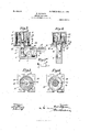
Cooperating with and arranged opposite each of the above described bolts 10, 10 is a mechanism applied to the frame 1 of the door and serving as a counterpart of the automatically operating hinge. This mechanism consists of a cylindrical casing 24 in which a pivot 25 is rotatively borne. In the lower casings these pivots are provided with ball bearings 26. The outer end of the pivot 25 that slightly projects from within the casing 24 is provided with a head 27 havingia notch 28 with flaring and slightly curved surfaces 29 to receive the blade shaped end of the bolt 10 or 10. Fitted around the said enlarged end or head 27 of the pin 25 and secured'to the outer open end of the casing 24 is a disk or cover 30 which is provided with a central groove 31 which is curved in the circle described by the swinging door. The inner surface of said groove is by the central aperture 32 of the disk 30 divided into two separate surfaces 33, 33 (Fig. 4) each being inclined inwards from said aperture and slightly curved. The outer edges of said surfaces, are level with those of the groove 281forming with `the upper and lower bolts will be thrust inward by the inclined surfaces of the groove 28, operating in the -above described manner7 the bolts l0 or l0 on the opposite side of the door to lock the same against longitudinal displacement. i/Vhen the bolts have reached the outer edges of the notches 23 they will be released and returned into normal position by the spring fingers v21. Asthe door continues to swing the bolts will travel in the curved grooves 31 and finally become disengaged from the mechanism in the frame.
On the opposite side the bolts l0 .(or l0) are locked in engagement with the pins 25 and act as hinges. As the door swings the same will turn with the pivots 25. Each of the pivots is acted upon by a helical spring 34 arranged in the casing 24, said spring tending to automatically close the door and to return the pin into normal position, i. e. in position where itsgroove 23 registers with the curved groove 3l in 'the disk 30.
The attachment of the helical spring in the upper casings 25 is slightly different from that in the lower casings. In the latter the upper end of the spring engages with the nose or catch 35 projecting down from a perforated disk 36 arranged between thel inner surface of the cover 30 and the collar 37 of the pivot 25. Adjustably borne in one of the perforations 33 of said disk 36 is a pin 39 with which a catch 40 of the pivot 25 is adapted to engage. The lower end of the spring loosely rests between radial ribs 41 arranged on the bottom of the casing 25 and is engaged with a lower nose or catch 42 of the pivot 25 (Figs. 7-10). AIn the upper casings the springs 34 have bends 43 to engage with catches 44 of the pivots 25, while the lower ends thereof are loosely passed through slots 45 made in stationarily applied disks 46 arranged below the collars 47 of the pivots 25 (Figs. 3-6).
I do not wish to restrict myself to the details of construction described and shown, since the same can be easily modified without deviating from the spirit of my invention, but
Vhatl claim and desire to secure by Letters Patent is:
In combination with the frame, of a door, automatically operating blades projecting outward from the upper and. lower ends of the door, one at each side thereof, pivots' rotatively borne in. said frame opposite the said blades and projecting outwardl therefrom, said pivots having cam shaped notches to receive said blades and to hold the same so as to be capable of turning with the said pivots, means to normally hold the blades in engagement with said pivots and means operating the said blades by the swinging movement of the door so as to lock the same at one side of the door and to permit those on the other side to disengage the pivots, substantially as and for the purpose specified.
Signed at New York this 1.3 day of Au.-
gust 1907.
KARL METZKER. Witnesses:
JosEPI-r E. CAvANAUGi-L MAX D. ORDMANN.
Priority Applications (1)
| Application Number | Priority Date | Filing Date | Title |
|---|---|---|---|
| US38850907A US883418A (en) | 1907-08-14 | 1907-08-14 | Swinging door. |
Applications Claiming Priority (1)
| Application Number | Priority Date | Filing Date | Title |
|---|---|---|---|
| US38850907A US883418A (en) | 1907-08-14 | 1907-08-14 | Swinging door. |
Publications (1)
| Publication Number | Publication Date |
|---|---|
| US883418A true US883418A (en) | 1908-03-31 |
Family
ID=2951857
Family Applications (1)
| Application Number | Title | Priority Date | Filing Date |
|---|---|---|---|
| US38850907A Expired - Lifetime US883418A (en) | 1907-08-14 | 1907-08-14 | Swinging door. |
Country Status (1)
| Country | Link |
|---|---|
| US (1) | US883418A (en) |
Cited By (2)
| Publication number | Priority date | Publication date | Assignee | Title |
|---|---|---|---|---|
| US4903636A (en) * | 1987-06-29 | 1990-02-27 | James Kroeker | Artificial habitat for aquatic animals |
| WO2021224189A1 (en) * | 2020-05-05 | 2021-11-11 | Emka Beschlagteile Gmbh & Co. Kg | Hinge lock |
-
1907
- 1907-08-14 US US38850907A patent/US883418A/en not_active Expired - Lifetime
Cited By (4)
| Publication number | Priority date | Publication date | Assignee | Title |
|---|---|---|---|---|
| US4903636A (en) * | 1987-06-29 | 1990-02-27 | James Kroeker | Artificial habitat for aquatic animals |
| WO2021224189A1 (en) * | 2020-05-05 | 2021-11-11 | Emka Beschlagteile Gmbh & Co. Kg | Hinge lock |
| US20230265695A1 (en) * | 2020-05-05 | 2023-08-24 | Emka Beschlagteile Gmbh & Co. Kg | Hinge lock |
| US12523076B2 (en) * | 2020-05-05 | 2026-01-13 | Emka Beschlagteile Gmbh & Co. Kg | Hinge lock |
Similar Documents
| Publication | Publication Date | Title |
|---|---|---|
| US226033A (en) | Ohaeles m | |
| US886108A (en) | Sash-lock. | |
| US883418A (en) | Swinging door. | |
| US566168A (en) | Removable window-sash | |
| US2913272A (en) | Lock for sliding doors | |
| US849072A (en) | Ventilating window-sash lock. | |
| US1219059A (en) | Car-door fastener. | |
| US477445A (en) | Albert a | |
| US218455A (en) | Improvement in reversible latches | |
| US521341A (en) | Fastener for meeting-rails of sashes | |
| US541132A (en) | Knob-spindle fastener | |
| US1189902A (en) | Lock or fastening device for hinged box members. | |
| US857322A (en) | Sash-fastener. | |
| JP4441342B2 (en) | Device for preventing misoperation of the shoji locking mechanism | |
| US596234A (en) | Sash-holder | |
| US308142A (en) | cutler | |
| US186341A (en) | Improvement in spring bolts or catches for sliding doors | |
| US594504A (en) | Said lainf | |
| US539653A (en) | Margaeet e | |
| US697939A (en) | Sash-tightening device. | |
| US1137818A (en) | Latch. | |
| US1137819A (en) | Latch. | |
| US161700A (en) | Improvement in reversible latches | |
| US973990A (en) | Sliding-door lock. | |
| US650039A (en) | Window-fastener. |