US8833020B2 - Thermal isolator ground pan for foundation of manufactured building - Google Patents
Thermal isolator ground pan for foundation of manufactured building Download PDFInfo
- Publication number
- US8833020B2 US8833020B2 US12/777,038 US77703810A US8833020B2 US 8833020 B2 US8833020 B2 US 8833020B2 US 77703810 A US77703810 A US 77703810A US 8833020 B2 US8833020 B2 US 8833020B2
- Authority
- US
- United States
- Prior art keywords
- ground
- pan
- foundation
- ground pan
- thermally
- Prior art date
- Legal status (The legal status is an assumption and is not a legal conclusion. Google has not performed a legal analysis and makes no representation as to the accuracy of the status listed.)
- Active
Links
- 238000004891 communication Methods 0.000 claims abstract description 12
- 238000011065 in-situ storage Methods 0.000 claims abstract description 9
- 239000006260 foam Substances 0.000 claims description 6
- 239000002023 wood Substances 0.000 claims description 4
- 239000004033 plastic Substances 0.000 claims description 2
- 238000003780 insertion Methods 0.000 claims 1
- 230000037431 insertion Effects 0.000 claims 1
- 239000011810 insulating material Substances 0.000 claims 1
- 238000000034 method Methods 0.000 abstract description 2
- 230000008014 freezing Effects 0.000 description 7
- 238000007710 freezing Methods 0.000 description 7
- 239000000463 material Substances 0.000 description 6
- 238000009434 installation Methods 0.000 description 3
- XLYOFNOQVPJJNP-UHFFFAOYSA-N water Substances O XLYOFNOQVPJJNP-UHFFFAOYSA-N 0.000 description 3
- 229910000831 Steel Inorganic materials 0.000 description 2
- 238000007792 addition Methods 0.000 description 2
- 230000008901 benefit Effects 0.000 description 2
- 239000002184 metal Substances 0.000 description 2
- 239000002689 soil Substances 0.000 description 2
- 239000010959 steel Substances 0.000 description 2
- 229920006328 Styrofoam Polymers 0.000 description 1
- 239000000853 adhesive Substances 0.000 description 1
- 230000001070 adhesive effect Effects 0.000 description 1
- 238000004873 anchoring Methods 0.000 description 1
- 230000000712 assembly Effects 0.000 description 1
- 238000000429 assembly Methods 0.000 description 1
- 238000009412 basement excavation Methods 0.000 description 1
- 239000011248 coating agent Substances 0.000 description 1
- 238000000576 coating method Methods 0.000 description 1
- 238000012217 deletion Methods 0.000 description 1
- 230000037430 deletion Effects 0.000 description 1
- 238000012986 modification Methods 0.000 description 1
- 230000004048 modification Effects 0.000 description 1
- 229920006395 saturated elastomer Polymers 0.000 description 1
- 239000008261 styrofoam Substances 0.000 description 1
- 238000010257 thawing Methods 0.000 description 1
Images


Classifications
-
- E—FIXED CONSTRUCTIONS
- E02—HYDRAULIC ENGINEERING; FOUNDATIONS; SOIL SHIFTING
- E02D—FOUNDATIONS; EXCAVATIONS; EMBANKMENTS; UNDERGROUND OR UNDERWATER STRUCTURES
- E02D31/00—Protective arrangements for foundations or foundation structures; Ground foundation measures for protecting the soil or the subsoil water, e.g. preventing or counteracting oil pollution
- E02D31/10—Protective arrangements for foundations or foundation structures; Ground foundation measures for protecting the soil or the subsoil water, e.g. preventing or counteracting oil pollution against soil pressure or hydraulic pressure
- E02D31/14—Protective arrangements for foundations or foundation structures; Ground foundation measures for protecting the soil or the subsoil water, e.g. preventing or counteracting oil pollution against soil pressure or hydraulic pressure against frost heaves in soil
-
- E—FIXED CONSTRUCTIONS
- E02—HYDRAULIC ENGINEERING; FOUNDATIONS; SOIL SHIFTING
- E02D—FOUNDATIONS; EXCAVATIONS; EMBANKMENTS; UNDERGROUND OR UNDERWATER STRUCTURES
- E02D27/00—Foundations as substructures
- E02D27/01—Flat foundations
- E02D27/02—Flat foundations without substantial excavation
-
- E—FIXED CONSTRUCTIONS
- E04—BUILDING
- E04B—GENERAL BUILDING CONSTRUCTIONS; WALLS, e.g. PARTITIONS; ROOFS; FLOORS; CEILINGS; INSULATION OR OTHER PROTECTION OF BUILDINGS
- E04B1/00—Constructions in general; Structures which are not restricted either to walls, e.g. partitions, or floors or ceilings or roofs
- E04B1/343—Structures characterised by movable, separable, or collapsible parts, e.g. for transport
- E04B1/34336—Structures movable as a whole, e.g. mobile home structures
- E04B1/34352—Base structures or supporting means therefor
-
- E—FIXED CONSTRUCTIONS
- E02—HYDRAULIC ENGINEERING; FOUNDATIONS; SOIL SHIFTING
- E02D—FOUNDATIONS; EXCAVATIONS; EMBANKMENTS; UNDERGROUND OR UNDERWATER STRUCTURES
- E02D2300/00—Materials
- E02D2300/0046—Foams
-
- Y—GENERAL TAGGING OF NEW TECHNOLOGICAL DEVELOPMENTS; GENERAL TAGGING OF CROSS-SECTIONAL TECHNOLOGIES SPANNING OVER SEVERAL SECTIONS OF THE IPC; TECHNICAL SUBJECTS COVERED BY FORMER USPC CROSS-REFERENCE ART COLLECTIONS [XRACs] AND DIGESTS
- Y10—TECHNICAL SUBJECTS COVERED BY FORMER USPC
- Y10S—TECHNICAL SUBJECTS COVERED BY FORMER USPC CROSS-REFERENCE ART COLLECTIONS [XRACs] AND DIGESTS
- Y10S52/00—Static structures, e.g. buildings
- Y10S52/11—Mobile-structure stabilizing anchor
Definitions
- the present invention relates to foundations for manufactured buildings. More particularly, the present invention relates to a ground pan that reduces frost heaving occurrences to foundations of manufactured buildings.
- Manufactured buildings such as manufactured or mobile homes and offices, are manufactured remote from an instillation site and moved on wheels to the installation site.
- the manufactured building typically includes long, longitudinal support beams underneath the building to support the floor of the building.
- a plurality of piers placed between a ground pan and the support beam support the building level on the site.
- Installed manufactured buildings also are connected to foundation systems to resist lateral and longitudinally wind forces on the building.
- These foundation systems use a ground pan and an elongated strut connected at a lower end to the ground pan and at the upper end to a support beam of the manufactured building.
- the elongated strut can be oriented parallel to a longitudinal axis of the support beam or extend laterally from underneath one support beam to connect to the adjacent support beam of the manufactured buildings.
- Such foundations provide resistance to wind forces in both the lateral and longitudinal directions.
- frost heave there are three factors that contribute to frost heave. These factors are the soil being sufficiently saturated with water, the atmospheric temperature, and the duration of the saturation and cold temperatures. Efforts to resist frost heave have been made. Typically in areas that experience significant frost heave, the foundation must be engineered and extend below the frost line. This requires excavation of an in-ground footing and installation of a rigid or engineered foundation such as concrete footers and pilings. In other areas, skirting attaches around the perimeter of the manufactured home. The skirting extends from a lower edge of the manufactured home to the ground. The skirting encloses the space between the ground and the bottom of the manufactured home. The skirting also prevents flow of air under the home.
- Skirting used on the perimeter of manufactured buildings placed at sites with pier supports is not entirely successful in reducing or eliminating frost heave. Even with skirting, manufactured buildings placed at sites with pier supports and not engineered foundations, are susceptible to frost heave of the ground below the ground pan.
- the present invention meets the need in the art by providing a foundation system for supporting a manufactured building having a support beam, comprising a ground pan having a planar surface received on a ground surface and a thermally insulative cap disposed on the ground pan, whereby the ground pan and thermally insulative cap define in situ a proximate thermally isolated ground column thereunder, with a pier positioned on the ground pan and extending into contact with the support beam for vertically supporting the support beam and transferring the mass of the manufactured home to the ground pan, whereby the thermally insulative cap restricts communication of heat from the proximate thermally isolated ground column for resisting frost heave.
- the present invention provides a method of resisting frost heave of a foundation system that supports a manufactured building having a support beam, comprising the steps of:
- ground pan and thermally insulative member define in situ a proximate thermally isolated ground column thereunder, which thermally insulative member restricts communication of heat from the proximate thermally isolated ground column for resisting frost heaving.
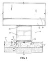
- FIG. 1 is a perspective view of a manufactured building and support foundation with a thermal isolator ground pan in accordance with the present invention.
- FIG. 2 is a detailed perspective view of an alternate embodiment of the thermal isolator ground pan according to the present invention.
- FIG. 3 is a perspective view of a foundation providing longitudinal support for a manufactured building with the thermal isolator ground pan illustrated in FIG. 1 .
- FIG. 4 is a perspective view of a foundation providing lateral support for a manufactured building with the thermal isolator ground pan illustrated in FIG. 1 .
- FIG. 5 is a detailed perspective view of an alternate embodiment of a thermal isolator foundation plate.
- FIG. 6 is a detailed perspective view of a ground pan with an alternate embodiment of a thermal isolator plate in accordance with the present invention.
- the present invention provides a thermal isolator ground pan 10 for use with a foundation generally 12 of a manufactured buildings 14 .
- Manufactured buildings have at least one longitudinally extended support beam 16 , and typically two, or more, such support beams.
- the ground pan 10 seats on the ground generally 18 .
- the ground pan 10 interacts with the ground 18 for resisting movement. Typically, this is accomplished by providing ground blades 20 that extend in a first direction substantially perpendicularly from a top surface of the ground pan. For example, opposing side edges of the ground pan 10 fold over to define a pair of opposing ground blades 20 that extend a first distance 24 from the top surface.
- the ground pan 10 is formed from a metal sheet.
- the ground pan 10 includes ground blades that extend from a perimeter of the ground pan and includes a plurality of legs 26 , with each leg extending from adjacent ground blades at intersections thereof.
- the legs 26 extend to a distal extent 28 that is a second distance 30 from the top surface, with the second distance 30 greater than the first distance 24 .
- the ground pan 10 includes a thermally insulative member 32 .
- the thermally insulative member 32 is a sheet that sits on the top surface of the ground pan 10 that spaces or separates the sheet from contact with the ground surface such as that below the ground pan, and can be attached such as with an adhesive.
- the thermally insulative sheet 32 is a foam sheet such as a STYROFOAM panel or sheet.
- the thermally insulative sheet 32 is defined by a spray-on thermal material. The spray-on thermal material sticks or attaches to the ground pan.
- the thermally insulative sheet (or spray-on material) seats inwardly on a bottom surface of the ground pan.
- the sheet 32 provides a thermally insulative layer or coating of between about 1 ⁇ 4 inch to 1 ⁇ 2 inch, or other thickness suitable for restricting thermal communication, as discussed below.
- a pier 34 positioned on the ground pan 10 extends between the ground pan and the support beam 16 for vertically supporting the support beam and for transferring the mass of the manufactured home to the ground pan.
- the pier in the illustrated embodiment comprises a stack of concrete blocks but can be a wood beam or other suitable load bearing material.
- the pier 34 can sit on the thermal sheet 32 , or in a pocket or opening (see 71 in FIG. 3 ) defined in the thermal sheet so that the pier sits directly on the ground pan 10 .
- a wood pad 36 seats between an upper surface of the pier 34 and the lower flange of the support beam 16 .
- the wood pad 36 can be tapered for wedging between the pier 34 and the support beam 16 .
- the ground pan 10 and the thermally insulative sheet 32 cooperatively define in situ a substantially axially aligned ground column generally 38 with a thermally isolated ground column 40 proximate the ground pan 10 .
- the ground column 38 below a frost line generally 42 communicates (generally 43 ) ground heat into the proximate thermally isolated ground column 40 .
- the foundation 12 reduces movement of the ground pan 10 caused by frost heave arising from the freezing and thawing of moisture-laden ground engaged by the ground pan.
- the ground heat communicates 43 through the ground column 38 and into the proximate thermally isolated ground column 40 .
- the thermally insulative sheet 32 aligned with the thermally isolative ground pan 10 caps the ground column 38 and restricts heat communication from the proximate thermally isolated ground column 40 to and through the ground pan 10 to the atmosphere.
- the proximate thermally isolated ground column 40 retains ground heat, and the proximate ground column experiences reduced freezing occurrences (compared to nearby portions of the proximate ground between the ground surface and the portion of the ground below the frost line 42 ). As a consequence, the occurrence of frost heave is reduced relative to the proximate thermally isolated ground column 40 , and movement of the ground pan 10 is thereby reduced.
- the thermally insulative sheet 32 provides a high resistance to heat communication generally referred to in the insulating trade as an R factor, compared to the R factor of the ground pan alone.
- FIG. 2 illustrates in perspective view an alternate embodiment of a ground pan 50 in accordance with the present invention.
- the ground pan 50 is molded from a plastic material and defines a floor 52 with a plurality of upstanding walls 54 that define chambers generally 56 .
- the chambers 56 are filled with a conventional fluidal foam that cures to define an insulative sheet 58 .
- the chambers 56 are covered with a firm thermally insulative sheet or panel.
- the ground pan 50 is gainfully used with a foundation for a manufactured home, as discussed above.
- the ground pan 50 and the thermally insulative sheet 58 cooperatively define in situ the ground column 38 and proximate thermally isolated ground column 40 relative to the ground pan 50 and the frost line 42 .
- the thermally insulative sheet 58 caps the ground pan 50 and restricts heat communication from the ground column 38 , and thus reduces occurrences of freezing of the proximate thermally isolated ground column 40 .
- the thermally isolative ground pan 10 finds gainful use in an alternate embodiment in which the pier or the foundation supports are elongated steel members extending between the ground pan and the support beam.
- the foundation can include or use lateral elongated members and/or longitudinal elongated members (relative to a longitudinal axis of the support beam 16 ).
- U.S. Pat. No. 6,634,150 discloses a foundation for manufactured homes that uses a lateral brace having a bottom end pivotably supported by the ground pan and a upper end pivotably attached to a beam connector adapted for clamping attachment to a lateral flange of a second support beam lateral of the first support beam.
- U.S. Pat. No. 7,140,157 discloses a foundation system for a manufactured building for preventing longitudinal movement.
- FIG. 3 illustrates in perspective view of an exemplary embodiment of a foundation system 60 according to U.S. Pat. No. 7,140,157, in which the thermally isolative sheet 32 seats on the ground pan 10 .
- the foundation system 60 includes a pair of rigid arms 62 and means, such as a pair of clamps 64 for attaching an upper end of the arm to the support beam 16 .
- Each arm 62 has a lower end 66 and an upper end 68 .
- Each lower end 66 and upper end 68 includes a bore for receiving a fastener, for pivotable support of the lower end to a connector 70 (such as a U-shaped bracket) attached to the ground pan and for pivotable attaching of the upper end 68 to the beam connector 64 connected to the beam 16 .
- the arms 62 may be of any suitably strong material, such as of one and one-half inch square steel tube.
- the ground pan 10 restricts downward and horizontal movement of the lower ends 66 of arms 62 and retains the lower ends in a fixed, but pivotable, position.
- the arms 62 are telescoping for selective length.
- the arms 62 communicate loading and wind forces to the ground pan 10 , while the ground pan and the thermally insulative sheet 32 cooperatively define in situ the ground column 38 and the proximate thermally isolated ground column 40 relative to the ground pan 40 and the frost line 42 .
- the thermally insulative sheet 32 caps the ground pan 10 and restricts heat communication from the ground column 38 , and thus reduces occurrences of freezing of the proximate thermally isolated ground column 40 .
- an alternate embodiment can have a single arm 62 (not illustrated) connected to a load bearing ground pan 40 using a pier, and gainfully use the termally insulative sheet 32 .
- FIG. 4 illustrates in perspective view a foundation 70 providing lateral wind resistance in accordance with a foundation of a type disclosed in U.S. Pat. No. 6,634,150, and further with the thermally isolative sheet 32 .
- the manufactured building 14 includes a pair of spaced-apart support beams 16 a and 16 b , such as a typical I-beam having a vertical web 72 and opposing upper and lateral flanges 74 , 76 .
- the ground pan 10 is disposed under a first of the support beams 16 a with the insulative sheet 32 .
- the pier 34 extends upwardly to contacting engagement with the support beam 16 a .
- a lateral brace assembly 78 such as elongated struts or telescoping metal tubes 79 a , 79 b pivotably attaches at a lower end 80 to a connector 82 attached to the ground pan 10 .
- An upper end 84 pivotably attaches to a beam connecter 86 attached to the second support beam 16 b .
- a fastener such as a bolt connects the telescoping tubes together.
- the elongated struts 79 in the lateral brace assembly communicate loading and wind forces to the ground pan 10 , while the ground pan 10 and the thermally insulative sheet 32 cooperatively define in situ the ground column 38 and the proximate thermally isolated ground column 40 relative to the ground pan 10 and the frost line 42 .
- the thermally insulative sheet 32 caps the ground pan 10 and restricts heat communication from the ground column 38 , and thus reduces occurrences of freezing of the proximate thermally isolated ground column 40 .
- a foundation may readily provide both lateral and longitudinal load resistance by using a longitudinal strut or arm 62 as illustrated in FIG. 3 together with a lateral strut assembly 78 as illustrated in FIG. 4 , while providing with the thermal sheet 32 reduced occurrences of frost heave movement of the foundation.
- FIG. 5 illustrates in a detailed perspective view an alternate embodiment of a thermal isolator foundation plate 90 using the thermally insulative sheet 32 .
- the foundation plate 90 includes openings 92 for receiving stakes 94 to secure the plate to the ground 18 .
- FIG. 6 illustrates a detailed perspective view of the ground pan 10 with an alternate embodiment in which the thermally isolative member is a cap 96 in accordance with the present invention.
- the thermally insulative cap 96 (depicted in cut-away view) has a planar sheet 98 and side walls 100 extending in a first direction substantially normal from perimeter edges. This defines an interior cavity 102 for receiving the ground pan 10 while the side walls 10 align contactingly with the walls 20 of the ground pan.
- the walls 100 may in alternate embodiments taper outwardly relative to a perimeter edge of the sheet 98 .
- the thermally insulative sheet 32 ( FIG. 5 ) and the thermally insulative cap 96 ( FIG. 6 ) form in situ the ground column 38 and the proximate thermally isolated ground column 40 relative to the ground plate 90 or ground pan 10 and the frost line 42 .
- the thermally insulative sheet 32 caps the ground plate 90 or ground pan 10 and restricts heat communication from the ground column 38 , and thus reduces occurrences of freezing of the proximate thermally isolated ground column 40 .
- thermal insulative member can readily be used with other anchoring members such as helical shafts or anchors that connect to support beams of the manufactured building for resisting loads.
- the present invention accordingly provides the foundation for manufactured buildings with the ground pan to cooperatively with the thermally insulative sheet for defining the proximate thermally isolated ground column to cap communication of ground heat therefrom and thereby resist frost heave occurrences. While this invention has been described in detail with particular references to illustrated embodiments thereof, it should be understood that many modifications, additions and deletions, in additions to those expressly recited, may be made thereto without departure from the spirit and scope of the invention.
Landscapes
- Engineering & Computer Science (AREA)
- Civil Engineering (AREA)
- Structural Engineering (AREA)
- Architecture (AREA)
- Mining & Mineral Resources (AREA)
- Life Sciences & Earth Sciences (AREA)
- Paleontology (AREA)
- General Life Sciences & Earth Sciences (AREA)
- General Engineering & Computer Science (AREA)
- Electromagnetism (AREA)
- Physics & Mathematics (AREA)
- Environmental & Geological Engineering (AREA)
- Hydrology & Water Resources (AREA)
- Building Environments (AREA)
Abstract
Description
Claims (4)
Priority Applications (10)
| Application Number | Priority Date | Filing Date | Title |
|---|---|---|---|
| US12/777,038 US8833020B2 (en) | 2009-05-11 | 2010-05-10 | Thermal isolator ground pan for foundation of manufactured building |
| CA2703536A CA2703536C (en) | 2009-05-11 | 2010-05-11 | Thermal isolator ground pan for foundation of manufactured building |
| US12/868,160 US8844209B1 (en) | 2009-05-11 | 2010-08-25 | Anchor pier for manufactured building |
| US14/473,773 US9970175B2 (en) | 2009-05-11 | 2014-08-29 | Anchor pier for manufactured building |
| US15/413,842 US10161098B2 (en) | 2009-05-11 | 2017-01-24 | Anchor pier for manufactured building |
| US16/231,699 US20190203440A1 (en) | 2009-05-11 | 2018-12-24 | Anchor Pier For Manufactured Building |
| US16/657,777 US10767337B2 (en) | 2009-05-11 | 2019-10-18 | Anchor pier for manufactured building |
| US16/990,531 US11319691B2 (en) | 2009-05-11 | 2020-08-11 | Anchor pier for manufactured building |
| US17/709,062 US11920316B2 (en) | 2009-05-11 | 2022-03-30 | Anchor pier for manufactured building |
| US18/435,449 US20240175229A1 (en) | 2009-05-11 | 2024-02-07 | Anchor Pier For Manufactured Building |
Applications Claiming Priority (2)
| Application Number | Priority Date | Filing Date | Title |
|---|---|---|---|
| US17710309P | 2009-05-11 | 2009-05-11 | |
| US12/777,038 US8833020B2 (en) | 2009-05-11 | 2010-05-10 | Thermal isolator ground pan for foundation of manufactured building |
Related Child Applications (1)
| Application Number | Title | Priority Date | Filing Date |
|---|---|---|---|
| US85802710A Continuation-In-Part | 2009-05-11 | 2010-08-17 |
Publications (2)
| Publication Number | Publication Date |
|---|---|
| US20100307073A1 US20100307073A1 (en) | 2010-12-09 |
| US8833020B2 true US8833020B2 (en) | 2014-09-16 |
Family
ID=43299712
Family Applications (1)
| Application Number | Title | Priority Date | Filing Date |
|---|---|---|---|
| US12/777,038 Active US8833020B2 (en) | 2009-05-11 | 2010-05-10 | Thermal isolator ground pan for foundation of manufactured building |
Country Status (1)
| Country | Link |
|---|---|
| US (1) | US8833020B2 (en) |
Cited By (10)
| Publication number | Priority date | Publication date | Assignee | Title |
|---|---|---|---|---|
| US20140298743A1 (en) * | 2011-05-11 | 2014-10-09 | Composite Technologies Corporation | Load transfer device |
| US20150135609A1 (en) * | 2013-11-15 | 2015-05-21 | Peter N. Glynos | Universal leveling device |
| US9932718B2 (en) | 2016-02-08 | 2018-04-03 | Home Pride, Inc. | Anchoring and stabilizing device for manufactured homes |
| US20180106010A1 (en) * | 2011-06-28 | 2018-04-19 | Neil Despotellis | Footing plates |
| US20190136567A1 (en) * | 2017-11-05 | 2019-05-09 | Cochrane Usa, Inc. | Base for a fence post |
| US10435857B1 (en) | 2019-02-19 | 2019-10-08 | Mary Michlig | Frost heave prevention system |
| US10774495B2 (en) | 2015-06-12 | 2020-09-15 | Oliver Technologies, Inc. | Stabilizer anchor assembly for manufactured building |
| US11002435B2 (en) | 2019-04-26 | 2021-05-11 | Oliver Technologies, Inc. | Anchor and light post assembly |
| US11421415B2 (en) * | 2020-08-26 | 2022-08-23 | Home Pride, Inc. | Hybrid foundation system |
| US11920316B2 (en) | 2009-05-11 | 2024-03-05 | Oliver Technologies, Inc. | Anchor pier for manufactured building |
Families Citing this family (8)
| Publication number | Priority date | Publication date | Assignee | Title |
|---|---|---|---|---|
| US20150204044A1 (en) * | 2014-01-17 | 2015-07-23 | Royal Adhesives & Sealants Canada Ltd. | Polyurethane Foam In Foundation Footings For Load-Bearing Structures |
| US10364544B2 (en) * | 2014-01-17 | 2019-07-30 | Royal Adhesives & Sealants Canada Ltd. | Polyurethane foam in foundation footings for load-bearing structures |
| US9447557B2 (en) * | 2014-02-21 | 2016-09-20 | Composite Panel Systems, Llc | Footer, footer elements, and buildings, and methods of forming same |
| USD901282S1 (en) | 2019-09-25 | 2020-11-10 | Dale Clayton Miller | Plate assembly |
| USD953843S1 (en) | 2019-09-25 | 2022-06-07 | Dale Clayton Miller | Pile system |
| US11828038B2 (en) | 2020-07-10 | 2023-11-28 | Dale Clayton Miller | Pile connection for horizontally fixing an elongated beam for a foundation support system |
| US11788246B2 (en) | 2020-12-14 | 2023-10-17 | Dale Clayton Miller | Micropile connection for supporting a vertical pile |
| CN114197542B (en) * | 2021-12-29 | 2023-06-23 | 新疆博际建筑工程有限责任公司 | Building boundary beam frost heaving prevention structure and construction method thereof |
Citations (25)
| Publication number | Priority date | Publication date | Assignee | Title |
|---|---|---|---|---|
| US3353852A (en) * | 1965-07-15 | 1967-11-21 | Concrete Steel Corp | Mount for tractor canopy post |
| US3380205A (en) * | 1965-05-07 | 1968-04-30 | Ratchford Tool Corp | Foundations for trailer type homes |
| US4189125A (en) * | 1978-12-08 | 1980-02-19 | Little Jim E | Ground support pads for mobile structures |
| US4348843A (en) * | 1980-08-04 | 1982-09-14 | Cairns Neil S | Mobile home support system |
| US4512120A (en) * | 1982-02-24 | 1985-04-23 | Lindal Sir W | Modular home construction |
| US4899497A (en) * | 1988-01-15 | 1990-02-13 | Madl Jr Jos | Foundation system and derivative bracing system for manufactured building |
| US5067289A (en) * | 1990-06-28 | 1991-11-26 | Ouderkirk Dale L | Foundation system for manufactured housing |
| US5419524A (en) * | 1993-03-12 | 1995-05-30 | Evans; Leonard W. | Weight distribution pad for trailers |
| US5487534A (en) * | 1991-11-15 | 1996-01-30 | Kajima Corporation | Laminated rubber vibration control device for structures |
| US5664394A (en) * | 1995-08-01 | 1997-09-09 | Diversitech Corporation | Base for equipment |
| US5697191A (en) * | 1996-04-10 | 1997-12-16 | Mackarvich; Charles J. | Manufactured home stabilizing foundation system |
| DE19834060A1 (en) * | 1998-07-29 | 1999-04-29 | Zueblin Ag | Permanent way position correction method |
| US5921035A (en) * | 1996-10-29 | 1999-07-13 | Kempf; Brian J. | Lockable screw post apparatus |
| US6119412A (en) * | 1998-12-24 | 2000-09-19 | Jackson; Richard F. | Plywood trailer pad system |
| US6298611B1 (en) | 2000-05-17 | 2001-10-09 | James Oliver | Ground anchor with self-aligning compression cap |
| US6505447B1 (en) | 2000-05-30 | 2003-01-14 | James Oliver | Foundation and method of installing the foundation comprising a ground engaging pan, cross braces clamped to flanges of a support frame, and cross braces clamped to each other at the crosspoints |
| US6634150B1 (en) | 2000-05-30 | 2003-10-21 | James Oliver | Foundation with lateral brace for manufactured home |
| US6718711B1 (en) * | 1999-01-26 | 2004-04-13 | Alutiiq Manufacturing Contractors, Llc | Prefabricated housing |
| US20050011149A1 (en) * | 2001-12-17 | 2005-01-20 | Ake Mard | Foundation structure |
| US20050081459A1 (en) * | 2003-10-17 | 2005-04-21 | Casey Moroschan | Foam pile system |
| US7140157B2 (en) | 2002-06-04 | 2006-11-28 | James Oliver | Foundation system for beam of manufactured home |
| US7313892B1 (en) * | 2004-05-13 | 2008-01-01 | Oliver James E | Support for manufactured housing |
| US7874767B2 (en) * | 2008-01-24 | 2011-01-25 | Nicolon Corporation | Woven geosynthetic fabric with differential wicking capability |
| US20110036025A1 (en) * | 2009-08-13 | 2011-02-17 | Boulay Luke F | Ground Anchor |
| EP2363535A1 (en) * | 2010-03-02 | 2011-09-07 | Exxag Investments Limited | Load bearing substructure of a structure or building |
-
2010
- 2010-05-10 US US12/777,038 patent/US8833020B2/en active Active
Patent Citations (27)
| Publication number | Priority date | Publication date | Assignee | Title |
|---|---|---|---|---|
| US3380205A (en) * | 1965-05-07 | 1968-04-30 | Ratchford Tool Corp | Foundations for trailer type homes |
| US3353852A (en) * | 1965-07-15 | 1967-11-21 | Concrete Steel Corp | Mount for tractor canopy post |
| US4189125A (en) * | 1978-12-08 | 1980-02-19 | Little Jim E | Ground support pads for mobile structures |
| US4348843A (en) * | 1980-08-04 | 1982-09-14 | Cairns Neil S | Mobile home support system |
| US4512120A (en) * | 1982-02-24 | 1985-04-23 | Lindal Sir W | Modular home construction |
| US4899497A (en) * | 1988-01-15 | 1990-02-13 | Madl Jr Jos | Foundation system and derivative bracing system for manufactured building |
| US5067289A (en) * | 1990-06-28 | 1991-11-26 | Ouderkirk Dale L | Foundation system for manufactured housing |
| US5487534A (en) * | 1991-11-15 | 1996-01-30 | Kajima Corporation | Laminated rubber vibration control device for structures |
| US5419524A (en) * | 1993-03-12 | 1995-05-30 | Evans; Leonard W. | Weight distribution pad for trailers |
| US5664394A (en) * | 1995-08-01 | 1997-09-09 | Diversitech Corporation | Base for equipment |
| US5697191A (en) * | 1996-04-10 | 1997-12-16 | Mackarvich; Charles J. | Manufactured home stabilizing foundation system |
| US5921035A (en) * | 1996-10-29 | 1999-07-13 | Kempf; Brian J. | Lockable screw post apparatus |
| DE19834060A1 (en) * | 1998-07-29 | 1999-04-29 | Zueblin Ag | Permanent way position correction method |
| US6119412A (en) * | 1998-12-24 | 2000-09-19 | Jackson; Richard F. | Plywood trailer pad system |
| US6718711B1 (en) * | 1999-01-26 | 2004-04-13 | Alutiiq Manufacturing Contractors, Llc | Prefabricated housing |
| US6298611B1 (en) | 2000-05-17 | 2001-10-09 | James Oliver | Ground anchor with self-aligning compression cap |
| US6505447B1 (en) | 2000-05-30 | 2003-01-14 | James Oliver | Foundation and method of installing the foundation comprising a ground engaging pan, cross braces clamped to flanges of a support frame, and cross braces clamped to each other at the crosspoints |
| US6634150B1 (en) | 2000-05-30 | 2003-10-21 | James Oliver | Foundation with lateral brace for manufactured home |
| US20050011149A1 (en) * | 2001-12-17 | 2005-01-20 | Ake Mard | Foundation structure |
| US7140157B2 (en) | 2002-06-04 | 2006-11-28 | James Oliver | Foundation system for beam of manufactured home |
| US7526899B1 (en) * | 2002-06-04 | 2009-05-05 | James Oliver | Foundation system for beam of manufactured home |
| US20050081459A1 (en) * | 2003-10-17 | 2005-04-21 | Casey Moroschan | Foam pile system |
| US7313892B1 (en) * | 2004-05-13 | 2008-01-01 | Oliver James E | Support for manufactured housing |
| US7874767B2 (en) * | 2008-01-24 | 2011-01-25 | Nicolon Corporation | Woven geosynthetic fabric with differential wicking capability |
| US8070395B2 (en) * | 2008-01-24 | 2011-12-06 | Jones David M | Woven geosynthetic fabric with differential wicking capability |
| US20110036025A1 (en) * | 2009-08-13 | 2011-02-17 | Boulay Luke F | Ground Anchor |
| EP2363535A1 (en) * | 2010-03-02 | 2011-09-07 | Exxag Investments Limited | Load bearing substructure of a structure or building |
Non-Patent Citations (19)
| Title |
|---|
| Cover page of set of documents for OTI foundation & anchor systems, each document is listed in this IDS separately, Oliver Technologies, Inc. 467 Swan Ave., Hohenwald, TN 38462; Dec. 4, 2002. |
| Dictionary.com, definition of "on", . * |
| Dictionary.com, definition of "on", <http://dictionary.reference.com/browse/on?s=t&Id=1089>. * |
| Oliver Technologies, Inc, "Quick Anchor Installation Instructions Model #OTCAP1, OTI Anchor Model#'s OT3044BP and OT3646BP", p. 11; 467 Swan Ave., Hohenwald, TN 38462; Nov. 2002. |
| Oliver Technologies, Inc., "Ground Anchor Installation Instructions", p. 12; 467 Swan Ave., Hohenwald, TN 38462; Nov. 2002. |
| Oliver Technologies, Inc., "I-Beam Frame Connections Swivel Connector (Part# 2001)", p. 14; 476 Swan Ave., Hohenwald, TN 38462; Nov. 2002. |
| Oliver Technologies, Inc., "Longitudinal Frame Connections OTQC", p. 13; 467 Swan Ave., Hohenwald, TN 38462; Nov. 2002. |
| Oliver Technologies, Inc., Installation Instructions OTI Auger Anchor, p. 10; 467 Swan Ave., Hohenwald, TN 38462; Nov. 2002. |
| Oliver Technologies, Inc.; Ground Anchor Installation Instructions, p. 9; 467 Swan Ave., Hohenwald, TN 38462; Nov. 2002. |
| Oliver Technologies, Inc.; Installation Instructions Galvanized Strapping, p. 15; 467 Swan Ave., Hohenwald, TN 38462; Nov. 2002. |
| Oliver Technologies, Inc.; Installation Instructions Galvanized Strapping, p. 9; 467 Swan Ave., Hohenwald, TN 38462; Jun. 2004. |
| Oliver Technologies, Inc.; Installation Instructions, Model #OTLT, Longitudinal Beam Connector, 467 Swan Ave., Hohenwald, TN 38462; Aug. 13, 2003. |
| Oliver Technologies, Inc.; Manufactured Housing Foundation Systems, A Division of Oliver Technologies, Inc.; Swivel Frame Tie, 467 Swan Ave., Hohenwald, TN 38462; Dec. 4, 2002. |
| Oliver Technologies, Inc.; Specifications, Oliver Technologies, Inc.-Adjustable Outrigger, p. 25; 467 Swan Ave., Hohenwald, TN 38462; Nov. 2002. |
| Oliver Technologies, Inc.; Specifications, Oliver Technologies, Inc.-Anchors and Components; pp. 26-28; 467 Swan Ave., Hohenwald, TN 38462; Nov. 2002. |
| Oliver Technologies, Inc.; Wind Zone Map, p. 16; 467 Swan Ave., Hohenwald, TN 38462; Nov. 2002. |
| Paul W. Hayman, et al., An Alternative Shallow Frost Protected HUD Compliant Foundation Design for Manufactured Homes, Dec. 1, 2009, pp. 1-9, appendix 5 pgs., Hayman Engineering, LLC. |
| Paul W. Hayman, MS, PE, A Frost Free Foundation (FFF): an Alternative Shallow Frost Protected Foundation Design for Manufactured Homes, Apr. 1, 2010, pp. 1-11, Hayman Engineering, LLC. |
| U.S. Department of Housing and Urban Development, Memorandum from Elizabeth A. Cocke, Deputy Administrator, Office of Manufactured Housing Programs, Comments on Recent Publications on Frost Free Foundation Design, Apr. 20, 2010, pp. 1-2, Washington, DC, www.hud.gov. |
Cited By (13)
| Publication number | Priority date | Publication date | Assignee | Title |
|---|---|---|---|---|
| US11920316B2 (en) | 2009-05-11 | 2024-03-05 | Oliver Technologies, Inc. | Anchor pier for manufactured building |
| US9074370B2 (en) * | 2011-05-11 | 2015-07-07 | Composite Technologies Corporation | Load transfer device |
| US20140298743A1 (en) * | 2011-05-11 | 2014-10-09 | Composite Technologies Corporation | Load transfer device |
| US20180106010A1 (en) * | 2011-06-28 | 2018-04-19 | Neil Despotellis | Footing plates |
| US20150135609A1 (en) * | 2013-11-15 | 2015-05-21 | Peter N. Glynos | Universal leveling device |
| US9062466B2 (en) * | 2013-11-15 | 2015-06-23 | Peter N. Glynos | Universal leveling device |
| US10774495B2 (en) | 2015-06-12 | 2020-09-15 | Oliver Technologies, Inc. | Stabilizer anchor assembly for manufactured building |
| US9932718B2 (en) | 2016-02-08 | 2018-04-03 | Home Pride, Inc. | Anchoring and stabilizing device for manufactured homes |
| US20190136567A1 (en) * | 2017-11-05 | 2019-05-09 | Cochrane Usa, Inc. | Base for a fence post |
| US11242694B2 (en) * | 2017-11-05 | 2022-02-08 | Cochrane Usa, Inc. | Base for a fence post |
| US10435857B1 (en) | 2019-02-19 | 2019-10-08 | Mary Michlig | Frost heave prevention system |
| US11002435B2 (en) | 2019-04-26 | 2021-05-11 | Oliver Technologies, Inc. | Anchor and light post assembly |
| US11421415B2 (en) * | 2020-08-26 | 2022-08-23 | Home Pride, Inc. | Hybrid foundation system |
Also Published As
| Publication number | Publication date |
|---|---|
| US20100307073A1 (en) | 2010-12-09 |
Similar Documents
| Publication | Publication Date | Title |
|---|---|---|
| US8833020B2 (en) | Thermal isolator ground pan for foundation of manufactured building | |
| US10767337B2 (en) | Anchor pier for manufactured building | |
| US11920316B2 (en) | Anchor pier for manufactured building | |
| US20170022682A1 (en) | Thermal Barrier for Building Foundation Slab | |
| US9206580B2 (en) | Side wall support pier and method for foundation of manufactured building | |
| US6616381B2 (en) | Piling solution | |
| US20160032554A1 (en) | Insulating Device for Building Foundation Slab | |
| US20110088336A1 (en) | Integrated post and jack system | |
| US6634150B1 (en) | Foundation with lateral brace for manufactured home | |
| US8011158B1 (en) | Footing for support of structure such as building | |
| US7131239B2 (en) | Structural slab and wall assembly for use with expansive soils | |
| US6536170B2 (en) | Manufactured home foundation | |
| CA2703536C (en) | Thermal isolator ground pan for foundation of manufactured building | |
| US9970193B1 (en) | System and method for the construction of dwellings | |
| US20090241448A1 (en) | Substructure and crawl space enclosure for factory constructed buildings | |
| US20020095880A1 (en) | Pier with diagonal strut | |
| KR102148250B1 (en) | the hybrid Insulated board with horizontal type compressive strength material and the foundation structure using the same | |
| AU2018201264B2 (en) | Building slab system | |
| CN214835089U (en) | Overhead building with adjustable base | |
| JP3903313B2 (en) | Basic structure of the structure | |
| CA2558794A1 (en) | Support and skirting system for factory built structures | |
| CN212053229U (en) | Stable steel accessory for building | |
| WO2025136198A1 (en) | A stabilization assembly for a building foundation | |
| AU2012227196B2 (en) | Shock resistant foundation system for a building | |
| CN120250703A (en) | A kind of wood frame air-film bearing platform and air-film building suitable for low-temperature frozen soil areas |
Legal Events
| Date | Code | Title | Description |
|---|---|---|---|
| STCF | Information on status: patent grant |
Free format text: PATENTED CASE |
|
| AS | Assignment |
Owner name: OLIVER TECHNOLOGIES, INC., TENNESSEE Free format text: ASSIGNMENT OF ASSIGNORS INTEREST;ASSIGNORS:OLIVER, SCOTT;OLIVER, JAMES;REEL/FRAME:036780/0944 Effective date: 20151013 |
|
| MAFP | Maintenance fee payment |
Free format text: PAYMENT OF MAINTENANCE FEE, 4TH YR, SMALL ENTITY (ORIGINAL EVENT CODE: M2551) Year of fee payment: 4 |
|
| MAFP | Maintenance fee payment |
Free format text: PAYMENT OF MAINTENANCE FEE, 8TH YR, SMALL ENTITY (ORIGINAL EVENT CODE: M2552); ENTITY STATUS OF PATENT OWNER: SMALL ENTITY Year of fee payment: 8 |