US8832938B2 - Ground mounted solar module integration system - Google Patents
Ground mounted solar module integration system Download PDFInfo
- Publication number
- US8832938B2 US8832938B2 US12/846,259 US84625910A US8832938B2 US 8832938 B2 US8832938 B2 US 8832938B2 US 84625910 A US84625910 A US 84625910A US 8832938 B2 US8832938 B2 US 8832938B2
- Authority
- US
- United States
- Prior art keywords
- support
- solar panel
- elongated member
- support mechanism
- attaching
- Prior art date
- Legal status (The legal status is an assumption and is not a legal conclusion. Google has not performed a legal analysis and makes no representation as to the accuracy of the status listed.)
- Active, expires
Links
Images


Classifications
-
- H—ELECTRICITY
- H02—GENERATION; CONVERSION OR DISTRIBUTION OF ELECTRIC POWER
- H02S—GENERATION OF ELECTRIC POWER BY CONVERSION OF INFRARED RADIATION, VISIBLE LIGHT OR ULTRAVIOLET LIGHT, e.g. USING PHOTOVOLTAIC [PV] MODULES
- H02S20/00—Supporting structures for PV modules
- H02S20/30—Supporting structures being movable or adjustable, e.g. for angle adjustment
-
- F24J2/525—
-
- F—MECHANICAL ENGINEERING; LIGHTING; HEATING; WEAPONS; BLASTING
- F24—HEATING; RANGES; VENTILATING
- F24S—SOLAR HEAT COLLECTORS; SOLAR HEAT SYSTEMS
- F24S25/00—Arrangement of stationary mountings or supports for solar heat collector modules
- F24S25/30—Arrangement of stationary mountings or supports for solar heat collector modules using elongate rigid mounting elements extending substantially along the supporting surface, e.g. for covering buildings with solar heat collectors
-
- F24J2/5239—
-
- F24J2/5245—
-
- F24J2/5256—
-
- F24J2/526—
-
- F24J2/5264—
-
- F—MECHANICAL ENGINEERING; LIGHTING; HEATING; WEAPONS; BLASTING
- F24—HEATING; RANGES; VENTILATING
- F24S—SOLAR HEAT COLLECTORS; SOLAR HEAT SYSTEMS
- F24S25/00—Arrangement of stationary mountings or supports for solar heat collector modules
- F24S25/10—Arrangement of stationary mountings or supports for solar heat collector modules extending in directions away from a supporting surface
- F24S25/16—Arrangement of interconnected standing structures; Standing structures having separate supporting portions for adjacent modules
-
- F—MECHANICAL ENGINEERING; LIGHTING; HEATING; WEAPONS; BLASTING
- F24—HEATING; RANGES; VENTILATING
- F24S—SOLAR HEAT COLLECTORS; SOLAR HEAT SYSTEMS
- F24S25/00—Arrangement of stationary mountings or supports for solar heat collector modules
- F24S25/60—Fixation means, e.g. fasteners, specially adapted for supporting solar heat collector modules
- F24S25/61—Fixation means, e.g. fasteners, specially adapted for supporting solar heat collector modules for fixing to the ground or to building structures
- F24S25/617—Elements driven into the ground, e.g. anchor-piles; Foundations for supporting elements; Connectors for connecting supporting structures to the ground or to flat horizontal surfaces
-
- F—MECHANICAL ENGINEERING; LIGHTING; HEATING; WEAPONS; BLASTING
- F24—HEATING; RANGES; VENTILATING
- F24S—SOLAR HEAT COLLECTORS; SOLAR HEAT SYSTEMS
- F24S25/00—Arrangement of stationary mountings or supports for solar heat collector modules
- F24S25/60—Fixation means, e.g. fasteners, specially adapted for supporting solar heat collector modules
- F24S25/63—Fixation means, e.g. fasteners, specially adapted for supporting solar heat collector modules for fixing modules or their peripheral frames to supporting elements
- F24S25/634—Clamps; Clips
-
- F—MECHANICAL ENGINEERING; LIGHTING; HEATING; WEAPONS; BLASTING
- F24—HEATING; RANGES; VENTILATING
- F24S—SOLAR HEAT COLLECTORS; SOLAR HEAT SYSTEMS
- F24S25/00—Arrangement of stationary mountings or supports for solar heat collector modules
- F24S25/60—Fixation means, e.g. fasteners, specially adapted for supporting solar heat collector modules
- F24S25/65—Fixation means, e.g. fasteners, specially adapted for supporting solar heat collector modules for coupling adjacent supporting elements, e.g. for connecting profiles together
-
- F—MECHANICAL ENGINEERING; LIGHTING; HEATING; WEAPONS; BLASTING
- F24—HEATING; RANGES; VENTILATING
- F24S—SOLAR HEAT COLLECTORS; SOLAR HEAT SYSTEMS
- F24S25/00—Arrangement of stationary mountings or supports for solar heat collector modules
- F24S25/70—Arrangement of stationary mountings or supports for solar heat collector modules with means for adjusting the final position or orientation of supporting elements in relation to each other or to a mounting surface; with means for compensating mounting tolerances
-
- H01L31/0422—
-
- H—ELECTRICITY
- H02—GENERATION; CONVERSION OR DISTRIBUTION OF ELECTRIC POWER
- H02S—GENERATION OF ELECTRIC POWER BY CONVERSION OF INFRARED RADIATION, VISIBLE LIGHT OR ULTRAVIOLET LIGHT, e.g. USING PHOTOVOLTAIC [PV] MODULES
- H02S20/00—Supporting structures for PV modules
- H02S20/10—Supporting structures directly fixed to the ground
-
- F24J2002/5281—
-
- F24J2002/5292—
-
- F—MECHANICAL ENGINEERING; LIGHTING; HEATING; WEAPONS; BLASTING
- F24—HEATING; RANGES; VENTILATING
- F24S—SOLAR HEAT COLLECTORS; SOLAR HEAT SYSTEMS
- F24S25/00—Arrangement of stationary mountings or supports for solar heat collector modules
- F24S2025/01—Special support components; Methods of use
- F24S2025/014—Methods for installing support elements
-
- F—MECHANICAL ENGINEERING; LIGHTING; HEATING; WEAPONS; BLASTING
- F24—HEATING; RANGES; VENTILATING
- F24S—SOLAR HEAT COLLECTORS; SOLAR HEAT SYSTEMS
- F24S25/00—Arrangement of stationary mountings or supports for solar heat collector modules
- F24S2025/01—Special support components; Methods of use
- F24S2025/02—Ballasting means
-
- Y—GENERAL TAGGING OF NEW TECHNOLOGICAL DEVELOPMENTS; GENERAL TAGGING OF CROSS-SECTIONAL TECHNOLOGIES SPANNING OVER SEVERAL SECTIONS OF THE IPC; TECHNICAL SUBJECTS COVERED BY FORMER USPC CROSS-REFERENCE ART COLLECTIONS [XRACs] AND DIGESTS
- Y02—TECHNOLOGIES OR APPLICATIONS FOR MITIGATION OR ADAPTATION AGAINST CLIMATE CHANGE
- Y02B—CLIMATE CHANGE MITIGATION TECHNOLOGIES RELATED TO BUILDINGS, e.g. HOUSING, HOUSE APPLIANCES OR RELATED END-USER APPLICATIONS
- Y02B10/00—Integration of renewable energy sources in buildings
- Y02B10/20—Solar thermal
-
- Y—GENERAL TAGGING OF NEW TECHNOLOGICAL DEVELOPMENTS; GENERAL TAGGING OF CROSS-SECTIONAL TECHNOLOGIES SPANNING OVER SEVERAL SECTIONS OF THE IPC; TECHNICAL SUBJECTS COVERED BY FORMER USPC CROSS-REFERENCE ART COLLECTIONS [XRACs] AND DIGESTS
- Y02—TECHNOLOGIES OR APPLICATIONS FOR MITIGATION OR ADAPTATION AGAINST CLIMATE CHANGE
- Y02E—REDUCTION OF GREENHOUSE GAS [GHG] EMISSIONS, RELATED TO ENERGY GENERATION, TRANSMISSION OR DISTRIBUTION
- Y02E10/00—Energy generation through renewable energy sources
- Y02E10/40—Solar thermal energy, e.g. solar towers
- Y02E10/47—Mountings or tracking
-
- Y—GENERAL TAGGING OF NEW TECHNOLOGICAL DEVELOPMENTS; GENERAL TAGGING OF CROSS-SECTIONAL TECHNOLOGIES SPANNING OVER SEVERAL SECTIONS OF THE IPC; TECHNICAL SUBJECTS COVERED BY FORMER USPC CROSS-REFERENCE ART COLLECTIONS [XRACs] AND DIGESTS
- Y02—TECHNOLOGIES OR APPLICATIONS FOR MITIGATION OR ADAPTATION AGAINST CLIMATE CHANGE
- Y02E—REDUCTION OF GREENHOUSE GAS [GHG] EMISSIONS, RELATED TO ENERGY GENERATION, TRANSMISSION OR DISTRIBUTION
- Y02E10/00—Energy generation through renewable energy sources
- Y02E10/50—Photovoltaic [PV] energy
-
- Y—GENERAL TAGGING OF NEW TECHNOLOGICAL DEVELOPMENTS; GENERAL TAGGING OF CROSS-SECTIONAL TECHNOLOGIES SPANNING OVER SEVERAL SECTIONS OF THE IPC; TECHNICAL SUBJECTS COVERED BY FORMER USPC CROSS-REFERENCE ART COLLECTIONS [XRACs] AND DIGESTS
- Y10—TECHNICAL SUBJECTS COVERED BY FORMER USPC
- Y10T—TECHNICAL SUBJECTS COVERED BY FORMER US CLASSIFICATION
- Y10T29/00—Metal working
- Y10T29/49—Method of mechanical manufacture
- Y10T29/4935—Heat exchanger or boiler making
- Y10T29/49355—Solar energy device making
Definitions
- Embodiments disclosed herein are directed to systems, devices for use with systems, and methods of mounting and retaining solar panels.
- Solar (e.g., photovoltaic) panels are often manufactured in the form of flat rigid structures. To facilitate the performance of the function of generating electricity, solar panels may be mounted in an area exposed to the sun or other source of light. Often, it is desirable to mount solar panels outdoors at an angle from the horizontal so that they will more directly face the sun during peak daylight hours as opposed to panels mounted flat on the ground. In some applications, it may be desirable to mount a number of solar panels together in an array in order to combine the power generation capabilities of the individual panels. In many instances, it may be desirable that mounting systems for solar panel arrays retain the solar panels in place. This may be accomplished by attaching the solar panels to one another in a mounting system and/or by mounting the panels to the mounting system.
- U.S. Patent Application Publication No. 2007/0133474 to Mascolo et al. describes a supported solar panel assembly including a solar panel module comprising a solar panel and solar panel module supports including module supports having support surfaces supporting the module, a module registration member engaging the solar panel module to position the solar panel module on the module support, and a mounting element.
- U.S. Pat. No. 6,534,703 to Dinwoodie describes a solar panel assembly for use on a support surface comprising a base, a solar panel module, a multi-position module support assembly, and a deflector.
- solar panels are mounted in arrays on the ground, e.g. in an open field.
- the ground includes local surface undulations, and the array of solar panels may be constructed to compensate for these undulations.
- a method for installing a solar panel array including acts of: providing a support mechanism including a support post pivotably attached to a support base; selecting an angular orientation of the support post with respect to the support base; setting the selecting an angular orientation of the support post; providing a solar panel; selecting a height on the support mechanism for attaching the panel; and attaching the panel at the selected height.
- an apparatus for mounting solar panels including: a support mechanism including a support post pivotably attached to a support base and an attachment module for attaching the solar panel to the support mechanism.
- a method of installing a solar panel array, the method including the steps of: obtaining a first support mechanism including a support post pivotably attached to a support base; selecting an angular orientation of the support post with respect to the support base; setting the selected an angular orientation of the support post; obtaining a first solar panel; selecting a height on the first support mechanism for attaching the first panel; and attaching the first panel to the first support mechanism at the selected height.
- the angular orientation of the support post is selected to compensate for a local undulation in a surface on which the first support mechanism is located.
- the height on the first support mechanism for attaching the panel is selected to compensate for the local undulation in the surface on which the first support mechanism is located.
- attaching the first panel to the first support mechanism includes coupling an attachment module to the first solar panel; and after coupling the attachment module to the first solar panel, coupling the attachment module to the first support mechanism.
- the first support mechanism includes a support frame coupled to the support post.
- the support frame includes: a first elongated member coupled to the support post and extending from a front end to a rear end along a direction substantially perpendicular to the support post; a second elongated member extending at an angle to the first elongated member between a front end coupled to the front end of the first elongated member and a rear end, the second elongated member include at least one facility adapted to receive the attachment module to couple the solar panel to the support frame; and a facility for adjusting the height of the first elongated member relative to the support base to a selected one of a plurality of heights.
- the method further including the steps of: selecting a height of the first elongated member relative to the support base; setting the height of the first elongated member relative to the support base to the selected height; and coupling the attachment module to the second elongated member.
- the support frame includes a facility for adjusting the angle of the second elongated member to the first elongated member to a selected one of a plurality of angles.
- the method includes: selecting a mounting angle of the solar panel; setting the angle of the second elongated member to the first elongated member to correspond to the mounting angle of the solar panel;
- Some embodiments include: obtaining a second solar panel; attaching the second solar panel to the first support mechanism by coupling an attachment module to the second solar panel; and, after coupling the attachment module to the second solar panel, coupling the attachment module to the first support mechanism.
- Some embodiments include: obtaining a second support mechanism, the second support mechanism including: a support post pivotably attached to a support base; and a support frame coupled to the support post.
- the support frame includes a first elongated member coupled the support post and extending from a front end to a rear end along a direction substantially perpendicular to the support post; and a second elongated member extending at an angle to the first elongated member between a front end coupled to the front end of the first elongated member and a rear end, the second elongated member include at least one facility adapted to receive a second attachment module to couple the solar panel to the support frame.
- the method includes, for the second support mechanism: selecting an angular orientation of the support post with respect to the support base and selecting a height on the first support mechanism for attaching the first panel, where at least one of the angular orientation of the support post and the height on the first support mechanism for attaching the first panel is selected to compensate for a local undulation in a surface on which the second support mechanism is located; setting the selected angular orientation of the support post; and attaching the first panel to the second support mechanism at the selected height.
- Some embodiments include: obtaining a second support mechanism, the second support mechanism including: a support post pivotably attached to a support base; and a support frame coupled to the support post, the support frame including: a first elongated member coupled to the support post and extending from a front end to a rear end along a direction substantially perpendicular to the support post; and a second elongated member extending at an angle to the first elongated member between a front end coupled to the front end of the first elongated member and a rear end, the second elongated member include at least one facility adapted to receive a second attachment module to couple the solar panel to the support frame.
- the method includes attaching the front end of the first elongated member of the first support mechanism to the rear end of the first elongated member of the second support mechanism.
- the front end of the first elongated member of the first support mechanism and the rear end of the first elongated member of the second support mechanism are attached using a facility which allows for the relative position and angular orientation of the elongated members to be adjusted. Some embodiments include selecting and setting the relative position and angular orientation of the attached elongated members.
- the relative position or angular orientation of the attached elongated members is adjusted to compensate for a variation in change in a slope of the surface underlying the first and second support mechanisms.
- a method is disclosed of installing a solar panel array, the method including the steps of: obtaining a first plurality of solar panels; placing a first plurality of support mechanisms, each including a support post pivotably attached to a support base, on a first region of a surface, the first region having a generally flat portion and localized undulations.
- the method includes, for each respective support mechanism in the first plurality: Selecting an angular orientation of the support post with respect to the support base; setting the selected an angular orientation of the support post; selecting an attachment height on the first support mechanism for attaching the first panel; and attaching at least one respective solar panel to the respective support mechanism at the selected height.
- the selected angular orientations and the attachment heights are selected to compensate for the local undulations in the first region such that each of the first plurality of panels are positioned with substantially the same orientation relative to the generally flat portion of the surface in the first region.
- the orientation relative to the generally flat portion of the surface in the first region includes a height of the respective panel relative to the generally flat portion of the surface in the first region.
- the panels in the first plurality of panels are each attached to a respective support mechanism while the support mechanism is unattached to any other support mechanisms.
- Some embodiments include attaching each support mechanism in the first plurality of support mechanisms to at least one other support mechanism in the first plurality of support mechanisms.
- Some embodiments include attaching cross bracing between at least two adjacent support mechanisms in the first plurality of support mechanisms.
- the support mechanisms in the first plurality are substantially identical.
- Some embodiments include: obtaining a second plurality of solar panels; placing a second plurality of support mechanisms, each including a support post pivotably attached to a support base, on a second region of the surface, the first region having a generally flat portion and localized undulations, the second region being adjacent to the first region and having a general slope which differs from a general slope of the first region.
- Some embodiments include, for each respective support mechanism in the second plurality: selecting an angular orientation of the support post with respect to the support base; setting the selecting an angular orientation of the support post; selecting an attachment height on the first support mechanism for attaching the first panel; and attaching at least one respective solar panel from the second plurality of solar panels to the respective support mechanism at the selected height, where the angular orientations and the attachment heights are selected to compensate for the local undulations in the second region such that each of the second plurality of panels a are positioned with substantially the same orientation relative to the generally flat portion of the surface in the second region.
- Some embodiments include attaching at least one of the support mechanisms of the first plurality with at least one support mechanisms in the second plurality.
- the support mechanism includes an attachment facility allows for the relative angular orientation of the support members to be adjusted to one of a plurality of orientations.
- the method includes attaching the support mechanism includes using the facility to set the relative angular orientation to compensate for the difference in the slopes of the first and second regions.
- the support mechanisms of the first and second pluralities of support mechanisms are substantially identical.
- substantially no portion of each of the support mechanisms in the first plurality is located below the surface.
- Some embodiments include driving one or more nails through the at least one of the support mechanisms and the surface to secure the support mechanism to the surface.
- a solar panel module mounting system component including: support base; a support post; a pivot pivotably coupling the support post to the support base; and a support frame coupled to the support post and including a facility for attaching a solar panel module.
- Some embodiments include one or more attachment modules adapted to couple to the solar panel module and to couple to the solar panel module at a selected height and orientation relative to the support base.
- the support frame includes: a first elongated member coupled at a substantially right angle to the support post and extending from a front end to a rear end; a second elongated member extending at an angle to the first elongated member from a front end coupled to the front end of the horizontal member and a rear end, and including the facility for attaching a solar panel module; and a facility for adjusting the height of the first elongated member relative to the support base to a selected one of a plurality of heights.
- Some embodiments include a facility for adjusting the angle of the second elongated member to the first elongated member to a selected one of a plurality of angles.
- the pivot is configured to allow the support post to pivot about at least two transverse axes. In some embodiments, the pivot is configured to allow the support post to pivot over at range angles from about 0 to at least about 5 degrees from normal to the support base. In some embodiments, the pivot is configured to allow the support post to pivot over at range angles from 0 to at least 10 degrees from normal to the support base. In some embodiments, the pivot is configured to allow the support post to pivot over at range angles from 0 to at least 30 degrees from normal to the support base.
- the support base includes a base pan for receiving and bearing the weight of a ballast, the base pan configured and arranged to receive the ballast in a position such that the ballast does not interfere with a pivoting motion of the support post.
- the front end of the first elongated member includes a facility for attachment to an adjacent solar panel module mounting system component.
- the facility for attachment of the first elongated member to an adjacent second solar panel module mounting system component is configured to allow adjustment of at least one of the attachment angle and the spacing between the component and the adjacent second solar panel module mounting system component.
- Some embodiments consist or consist essentially of the support base; the support post; the pivot; the support frame, the one or more attachment modules, and attachment hardware.
- Some embodiments consist or consist essentially of the support base; the support post; the pivot; the support frame, the one or more attachment modules, one or more cross bracing members adapted to extend from the component to an adjacent support component, and attachment hardware.
- the attachment hardware consists essentially of nuts, bolts, and screws.
- the support base, pivot, and support post includes a first integral unit; the support frame includes a second integral unit; and the attachment module includes a third integral unit.
- the support base, pivot, and support post and the support frame include a first integral unit; and the attachment module includes a third integral unit.
- the component deployed on a surface e.g., the ground
- substantially no portion of the component extends through the surface
- a solar panel module mounting system including: a first plurality of support mechanisms configured to receive a first plurality of solar panel modules, positioned on a first region of a surface (e.g., the ground), the first region having a generally flat portion and localized undulations, and each support mechanism including: a support base; a support post; a pivot pivotably coupling the support post to the support base allowing the support post to pivot to selected one of a plurality of angular orientations relative to the support base; and a support frame coupled to the support post at a selected one of a plurality of attachment heights relative to the support base, and including a facility for attaching a solar panel module.
- the respective selected angular orientation and attachment height compensates for the localized undulations such that each of the first plurality of solar panel modules is positioned with a substantially uniform height above the generally flat portion of the first region.
- each support mechanism is directly coupled to at least one other support mechanism.
- each solar panel module extends between and is supported by a pair of support mechanisms.
- the support mechanisms are substantially identical.
- each support mechanism includes a fixture configured to allow coupling between the support mechanism and another support mechanism and adapted to allow coupling at a selected one of a plurality of relative positions of the coupled mechanisms.
- each support mechanism of the second plurality includes: a support base; a support post; a pivot pivotably coupling the support post to the support base allowing the support post to pivot to selected one of a plurality of angular orientations relative to the support base; and a support frame coupled to the support post at a selected one of a plurality of attachment heights relative to the support base, and including a facility for attaching a solar panel module.
- the respective selected angular orientation and height compensates for the localized undulations such that each of the second plurality of solar panel modules is positioned with a substantially uniform height above the generally flat portion of the second region.
- the support mechanism includes an attachment facility allowing for the relative angular orientation of the support members to be adjusted to one of a plurality of orientations.
- the method includes attaching the support mechanisms includes using the facility to set the relative angular orientation to compensate for the difference in the slopes of the first and second regions.
- the support mechanisms of the first and second pluralities of support mechanisms are substantially identical.
- substantially no portion of each support mechanisms of the first and second pluralities is located below the surface.
- Some embodiments include one or more nails extending through the at least one of the support mechanisms and the surface to secure the support mechanism to the surface.
- FIG. 1 is an array of solar panel modules
- FIG. 2A is a perspective view of a support base
- FIG. 2B is a perspective view of a support base with ballast
- FIG. 3 is a perspective view of a support frame
- FIG. 4A is perspective view of a support frame mounted on a support base
- FIG. 4B is a side view of the support frame mounted on a support base of FIG. 4A ;
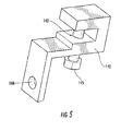
- FIG. 5 is an attachment module of a solar module mounting system
- FIG. 6A is a perspective view of the top side of a solar panel module illustrating attachment modules mounted on the solar panel module;
- FIG. 6B is a view from the rear underside of a solar panel module illustrating attachment modules mounted on the solar panel module;
- FIG. 6C is a view from underneath a solar panel module illustrating attachment modules mounted on the solar panel module according to an aspect of the present inventions
- FIG. 7 is a perspective view of a solar panel module mounted to a support frame and support base
- FIG. 8 is a rear perspective view of an array of solar panel modules featuring cross bracing
- FIG. 8A is a rear perspective view of an array of solar panel modules featuring cross bracing
- FIG. 9 is a rear perspective view of an array of solar panel modules deployed on undulating ground.
- FIG. 9A is a side perspective view of an array of solar panel modules deployed on undulating ground having regions with differing slope
- FIGS. 10A-10D are perspective views of attachment modules of a solar panel module mounting system
- FIG. 11 is a flowchart of a method of forming an array of solar panel modules
- FIG. 12A is a perspective view of an attachment module of a solar module mounting system
- FIG. 12B is a perspective view of an attachment module of a solar module mounting system attached to a solar panel module.
- FIG. 1 illustrates an example of a section of an array of solar panel modules 100 that may be deployed on a mounting surface, for example, an area of open ground such as a field. Aspects of the present embodiments may be applied to other mounting surfaces, such as roof structures.
- the array 100 in this example includes a plurality of solar panel modules 110 .
- solar panel module 110 is a packaged interconnected assembly of solar cells, e.g., photovoltaic cells.
- the solar panel module may be used as a component in a larger photovoltaic system to offer electricity for commercial and residential applications.
- the solar panel modules 110 are illustrated in FIG. 1 as being mounted at an angle from the horizontal, but in some embodiments, the solar panel modules may be mounted at angles other than that illustrated in FIG. 1 or even horizontally.
- the solar panel modules 110 may in some embodiments be mounted at different angles throughout the array 100 and uniformly in others such as the one shown in FIG. 1 .
- the solar panel modules 110 are shown in FIG. 1 facing away from what will be described herein as the Top side of array 100 . What is described as the Top side may correspond to geographical North position of the array.
- the Top side may be positioned approximately to the North so that the tilted faces of the panel modules are directed generally toward the South, e.g., tilted to more squarely face the direction of the sun for an installation north of the equator.
- deflector elements may be mounted facing the lateral sides (i.e., the sides perpendicular to the Top side) at the edges of the array, or in other positions on the array to deflect wind currents.
- Solar panel modules 110 in this example are mounted on support frames 120 which are in turn mounted on support bases 130 (sometimes referred to, collectively, as a support mechanism).
- a support frame is a support structure that may be used to support at least a portion of a solar panel; in this example, each support frame 120 is used to support a side of a solar panel module 110 .
- a support base is a support structure which contacts the ground and supports one or more support frames 120 . Examples of support frame 120 and support base 130 are described more fully below.
- arrays featuring any other number of solar panel modules 100 arranged in any number of rows and columns may be used.
- the array is formed with many panels over a large area e.g. and acre, several acres, or more.
- support frame 120 and support base 130 are shown as separate components, but, in some embodiments, they may be integrated in a single unit.
- FIG. 2A is a perspective view of a support base 130 .
- the support base includes a support post 131 connected to a base pan 132 .
- support post 131 is connected to base pan 132 with a pivot 133 .
- the pivot 133 allows the angle of the support post 131 relative to base pan 132 to be adjusted.
- Pivot 133 includes two pivot bolts 134 a and 134 b , allowing post 131 to pivot in two transverse directions.
- support post 131 may be positioned at a variety of angles.
- support post 131 may be positioned at any selected angle in a range less than 30 degrees from normal to base pan 132 .
- Other embodiments may have greater or lesser angular ranges, e.g.
- any other suitable type of pivot known in the art may be used, including, e.g., a ball and socket joint, a saddle joint, a ball bearing, etc.
- the angle of support post 131 may be selected to compensate for local undulations in the ground on which base pan 132 sits. For example, if the ground under base pan 132 had a local tilt of 20 degrees along a given direction, the angle of support post 131 could be adjusted to 20 degrees in the opposite direction, thereby compensating for the local tilt. Once the angle of support post 131 is chosen, pivot bolts 134 a and 134 b may be tightened to prevent further pivoting thereby setting the angle in place.
- Support post 131 includes an attachment mechanism (sometimes referred to as a facility), which in this example is support host bolt hole 135 , which may be used to attach post 131 to support frame 120 . As described in greater detail below, support post 131 may be attached to support frame 120 at a variety of heights, providing further flexibility to compensate for local undulations in the ground on which base pan 132 sits.
- attachment mechanism sometimes referred to as a facility
- support host bolt hole 135 which may be used to attach post 131 to support frame 120 .
- support post 131 may be attached to support frame 120 at a variety of heights, providing further flexibility to compensate for local undulations in the ground on which base pan 132 sits.
- ballast 136 may be placed on support pan 132 to provide support base 130 with mass that may assist in keeping array 100 securely in place.
- ballast 136 may comprise standard size concrete blocks, such as, for example, blocks with dimensions of 8 inches wide ⁇ 8 inches tall ⁇ 16 inches long, which may be available at numerous home improvement and/or building supply stores.
- base pans 132 are designed to permit use with standard sized, commercially available blocks, the need to ship heavy ballast elements along with other elements of the system may be reduced (although one could ship the ballast elements or design ballast element specifically for use with base pans 132 ). A purchaser/installer of the system could purchase or construct the ballast blocks locally.
- ballast 136 may include concrete blocks made at or near the site where array 100 is to be positioned.
- Ballast 136 in some embodiments may be made from any concrete mix that is intended to withstand the elements for an appropriate period of time, such as cement intended for outdoor applications and having an intended life span of 30+ years.
- Ballast 136 may in some embodiments be made using a Portland Type III concrete with air entertainment of about 5%. This concrete is a high early strength, normal weight concrete with a fully cured strength of 5,000 psi, and is available from Precast Specialties Inc. of Abington, Mass.
- ballast 136 may be formed from materials such as, for example, rocks, metal, natural or recycled rubber, or Quazite®, a polymer concrete available from Hubbell Lenoir City, Inc. of Lenoir City, Tenn., or other materials.
- ballast elements 136 are illustrated in FIG. 2B , it is to be understood that alternate embodiments may include, for example, left and right and/or front and back ballast elements having different configurations, multiple ballast elements positioned in any suitable configuration, or a single ballast element.
- these ballast elements may comprise, for example, standard sized building materials, including, for example, standard sized bricks with dimensions of 35 ⁇ 8 inches wide ⁇ 21 ⁇ 4 inches high ⁇ 8 inches long.
- Other embodiments feature bricks with a of nominal size of 8′′ ⁇ 8′′ ⁇ 16′′, although other size blocks may be used. This is a nominal size, typically the true dimensions are smaller in each direction by 1 ⁇ 8-1 ⁇ 4′′. Any other dimensions may be used.
- ballast elements may be mounted on base pan 132 in a stacked or a side-by-side configuration, or both.
- ballast 136 is placed on base pan 132 .
- ballast 136 may be attached or affixed to base pan 132 using any suitable means including fasteners, adhesives, hook and loop materials, etc.
- Base pan 132 may include a textured surface or retaining features to help maintain the placement of ballast 136 .
- ballast 136 one or more nails (e.g., 12 inch long nails) may be driven through base pan 132 into the ground below to secure the support base 136 .
- base pan 132 may include one or more holes, slots, etc. (not shown) to receive the nails and allow the nails to pass through the base pan 132 into the ground.
- support base 130 or any component thereof may also contain one or more wire chases (not shown) that can be used for running electrical wire through the support base 130 .
- wire chases may provide integrated wire management (e.g., allowing the electrical interconnection of two or more solar panel modules 110 ) and integrated grounding capabilities (e.g., accommodating one or more ground wires).
- support frame 120 includes a horizontal member 125 .
- the front end of horizontal member 125 includes a front support frame attachment facility 126 .
- the rear end of horizontal member 125 includes a rear support frame attachment facility 127 .
- the front support frame attachment facility 126 of one support frame 120 attaches to rear support frame attachment facility 127 of another support frame 120 to form columns of support frames 120 in array 100 .
- Rear support frame attachment facility 127 receives the front support frame attachment facility 126 of an adjacent support frame 120 .
- the attachment facilities 126 and/or 127 may include multiple horizontally spaced bolt holes, allowing the spacing between support frames (and hence modules 110 ) to be adjusted as desired.
- the rear attachment facility 126 includes six horizontally spaced bolt holes, while the front attachment facility 127 includes two horizontally spaced bolt holes, allowing for twelve possible spacings.
- support frames 120 may be a pivotably connected, allowing for adjustment of the angle at which horizontal members meet. This allows for construction of an array 100 where the angular orientation of modules 110 may vary row to row. Accordingly, support frames 120 allow for a great deal of flexibility in the positioning of modules 110 in array 100 .
- support frame 120 includes angled member 128 which includes a facility to permit attachment of panels to the frame.
- rear mounting hole 150 is provided on the rear portion of angled member 128 and provides locations for the attachment of attachment modules 140 , described in detail below.
- an attachment module 140 mounted to angled member 128 through rear mounting holes 150 may be attached to a solar panel module 110 proximate a Top edge 210 of the solar panel module 110 that is vertically higher than a Bottom edge 220 of the solar panel module when the solar panel module 110 is mounted on some embodiments of certain aspects of the present embodiments.
- Some embodiments include a facility which allows for the adjustment of the angular orientation of angled member 128 relative to horizontal member 125 .
- support frame 120 is constructed as an integral unit, with a fixed orientation of horizontal member 125 and angled member 128 .
- the Bottom edge 220 of solar panel module 110 may be attached with another attachment module 140 to forward mounting slots 160 on angled member 128 .
- Multiple forward mounting slots 160 are provided to allow flexibility in mounting panel modules 110 of various sizes.
- FIGS. 4A and 4B show a pair of attachment modules 140 , a first one attached to mounting holes 150 and second one attached to mounting slots 160 of angled member 128 .
- the distance between the pair of modules 140 may be coarsely adjusted by choosing which mounting slot 160 the second attachment module 140 is mounted to, and more finely adjusted by slidably adjusting the position at which the module is mounted within the slot.
- edges of two solar panel modules 110 may be attached to respective sides of angled member 128 using attachment modules 140 . As shown in FIG. 1 , this allows solar panel modules 110 to be attached to form the rows of the array 100 .
- support frame 120 includes a support post attachment mechanism 121 which allows attachment of support frame 120 to support post 131 .
- this attachment mechanism allows the height of support frame 120 above support pan 132 to be adjusted.
- support post attachment mechanism 121 includes several bolt holes spaced apart vertically. Mechanism 121 receives support post 131 and support post 131 is bolted to mechanism 121 with bolt 122 at a desired height using support post bolt hole 135 .
- support base 130 and support frame 120 may be constructed as an integral unit.
- support frame 120 may also contain one or more wire chases (not shown) that can be used for running electrical wire through the support frame 120 .
- wire chases may provide integrated wire management and integrated grounding capabilities.
- FIG. 4 is an enlarged view of attachment module 140 .
- Attachment module 140 may in some embodiments include a threaded hole 142 and a non-threaded hole 144 .
- attachment module 140 may be attached to support frame 120 with an appropriate attachment mechanism.
- a bolt is used to attach attachment module 140 to support frame 120 .
- a metal pin or a clip may be used, or other attachment devices or mechanisms as would be apparent to one of skill in the art based on the disclosure provided herein.
- Attachment module 140 may in some embodiments be made from 6061-T6 aluminum which can be anodized if desired.
- the attachment module 140 can also be made from other metal or some other material of sufficient strength. Where a conductive material is selected, the attachment module may be used to assist in passing ground among panels.
- the attachment module may be formed by machine cutting, but can also be extruded, laser cut, or water jet cut or formed using another suitable manufacturing method.
- FIG. 6A illustrates one embodiment of attachment module 140 according to one aspect of the present embodiments, mounted proximate the corners of solar panel module 110 .
- the attachment modules 140 may be made of a metal such as aluminum.
- the attachment modules 140 may be made of a conductive material to assist in grounding of the panel modules or may include a grounding path.
- attachment module 140 includes an attachment mechanism which in this example is a threaded hole for a bolt which may be used to attach the attachment modules 140 to a solar panel module 110 .
- the attachment module 140 may also include second, non-threaded holes for bolts 145 that may used to attach (or facilitate attaching) an attachment module 140 to support frame 120 (e.g. at rear mounting hole 150 or front mounting slot 160 of angled member 128 ).
- Other attachment mechanisms may be employed with attachment modules 140 , including, for example, screws, adhesives, clips, or solder.
- this particular attachment module is compatible for use with solar panels provided by multiple suppliers.
- This particular attachment module is also compatible for use with solar panel mounting systems provided by multiple suppliers.
- Other designs for compatibility with multiple suppliers may be provided based on the disclosure provided herein and different attachment modules may be designed for use with different solar panels but made compatible for use with a common support frame configuration.
- attachment module 140 is configured to permit it to be attached to a plurality of different panel modules and/or panel module mounting systems available in the market.
- FIGS. 6A-6C illustrate one example of how attachment modules 140 may be utilized to attach solar panel modules 110 to support frame 120 .
- FIG. 6B illustrates a solar panel module with three attachment modules 140 attached and one attachment module 140 unattached.
- an attachment module 140 may be attached to a solar panel module 110 by a threaded bolt 145 passing through a threaded hole in attachment module 140 to secure attachment module 140 to an inner edge of solar panel module 110 . This provides for positioning and alignment of solar panel module 110 relative to support frame 128 .
- Attachment modules 140 may be attached through non-threaded holes or slots to support frame 120 by bolts passing through one of rear mounting hole 150 and forward mounting slots 160 for a rear and a forward attachment module 140 respectively.
- solar panel modules 110 may be secured in place relative to support frame 120 and relative to one another in a fashion compatible with a number of commercially available solar panels.
- Other configurations may be designed to permit compatibility with multiple panel types whether attaching at this portion of the solar panel or designed for integration with future solar panels, based on the disclosure provided herein.
- FIG. 7 shows a solar panel module 110 with a first lateral edge 230 and a second lateral edge 240 attached to first and second support frames 120 A and 120 B, respectively.
- the assembly shown in FIG. 7 can be considered to be a basic unit which may be repeated as shown in FIG. 1 to form the array 100 .
- FIG. 8 shows a rear view of the array 100 of FIG. 1 .
- Cross bracing 801 provides additional support for solar panel modules 110 .
- the cross bracing includes three bracing members which extend horizontally between adjacent columns of support frames 120 .
- any other suitable cross bracing or mechanical support members may be used.
- the embodiment in FIG. 8A included only two cross bracing members extending between adjacent pairs of support frames 120 a and 120 b.
- FIG. 9 is a rear perspective view of the array 100 deployed on undulating ground.
- the ground 900 is generally flat and level, but includes local portions 901 having deviating heights and portion 902 which has a deviating height and tilt angle.
- Array 100 has been adjusted to compensate for the undulation in the ground, such that the height and tilt angle of panels 110 of array 100 are fixed relative to the flat and level portion of round 900 across the entire array.
- Three support bases 130 a are a positioned on the flat level portion or the ground.
- support posts 131 a are oriented normal to their respective base pans 132 a and are attached to their respective support frame 120 a at equal heights.
- Two support bases 130 b are positioned on portions 901 of ground 900 which are level, but have heights which deviate from the flat and level portion of ground 900 .
- support posts 131 b are also oriented normal to their respective base pans 132 b . However, they are attached to their respective support frames 120 b at heights which compensate for the local height deviation.
- One support base 130 c is positioned on portion 902 of ground 900 which has both a height and a tilt angle which deviates from the flat and level portion of ground 900 .
- support post 131 c is oriented at an angle from normal to its respective base pan 132 b , to compensate for the tilt of portion 902 .
- Support post 131 c is also attached to its respective support frame 120 b at a height which compensates for the local height deviation of portion 902 .
- ground 900 may be generally flat and inclined, with local undulations.
- array 100 may be adjusted to compensate for the undulation in the ground, such that the height and tilt angle of panels 110 of array 100 are fixed relative to the flat and inclined portion of ground 900 across the entire array (or portions thereof).
- ground 900 may include a first region 910 and a second region 912 which are both generally flat with local undulations, but which are inclined at different slopes.
- support frames 120 a and 120 b may be pivotally connected (as discussed in detail above), the array can accommodate the regions of ground having varying slope. Note that although two regions of varying slope are shown, and number may be accommodated. Accordingly, array 100 may be easily installed over large areas of terrain without the need for specially constructed parts (i.e., support frames 120 in array 100 may be all identical or substantially identical components.)
- the devices and techniques described herein allow ground mounted solar panel module support arrays to be designed and constructed with ease and flexibility. Local undulations may be compensated for, and various suitable row and column spacings and angular orientations may be used.
- Support frame 120 , support base 130 can be made from metals (such as stainless steel, mild steel, aluminum, etc), UV resistant plastic, fiberglass, concrete, or other materials.
- one or more of base pans 132 may include a pad or sole on its underside.
- the sole may be made from any suitable material, e.g. a textured material which improved the grip of base pans 132 on the supporting surface. In cases where base pans 132 are not placed on the ground but, e.g. on a roof surface, material that can be considered an “inert pad” by the roofing industry may be used.
- the sole may be made from recycled, non-vulcanized crumb rubber, such as that available from Unity Creations Ltd. of Hicksville, N.Y.
- the sole may be made from natural rubber, EPDM (Ethylene Propylene Diene Monomer—a rubber roofing material), or another roofing material that may protect the roof or other surface upon which array 100 may be mounted from damage.
- the sole may be attached to the underside of base pan 132 using any suitable attachment, e.g. adhesive, fasteners, etc.
- FIGS. 10A-10D show alternative embodiments of attachment module 140 .
- attachment module 140 a includes upper member 301 and lower member 302 .
- An inner edge of panel 110 (not shown) can be attached between the upper and lower members.
- the inner edge may include a hole (e.g. a pre-formed hole provided by the panel manufacturer).
- Threaded bolt 303 can pass through a threaded bolt hole in the lower member, through the hole in the inner edge, and into a threaded bolt hole in upper member 301 .
- Holes 304 in lower member 302 may be used to attach the attachment module 140 a to support frame 120 , e.g. using an attachment bolt.
- attachment module 140 b includes a c-shaped member 305 and a flat angled member 306 .
- An inner edge of panel 110 (not shown) can be attached between the members 305 and 306 .
- Threaded bolt 307 may pass through a threaded bolt hole in the c-shaped member to clamp the inner edge between members 305 and 306 .
- Slot 308 in flat angled member 306 may be used to attach the attachment module 140 a to support frame 120 , e.g. using an attachment bolt.
- attachment module 140 c may be used for attachment to a panel module 110 which lacks an inner edge along its lateral side, but includes an inner edge along its Top or Bottom side. Attachment module 140 a allows for the panels of this type to be mounted to support frames 120 of the type shown in FIG. 1 without additional modification.
- Attachment module 104 c includes a c-shaped member 309 and an extension member 310 .
- a Top or Bottom inner edge of panel 110 (not shown) can be attached between the c-shaped member 309 , and portion 311 of attachment member 310 .
- Threaded bolt 307 may pass through a threaded bolt hole in the c-shaped member to clamp the inner edge between members 305 and 306 .
- Attachment module 140 c may be attached to panel module 110 proximal to a corner of the panel, such that portion 312 of extension member 310 extends out past the lateral side of the panel for mounting to support frame 120 .
- Hole 313 in attachment member 310 may be used to attach the attachment module 140 c to support frame 120 , e.g. using an attachment bolt. Note that although exemplary dimensions are provided in the figure, any suitable dimensions may be used.
- attachment module 140 d includes upper member 301 and lower member 304 .
- the members are connected by at pivot 316 , thereby forming “jaws” that can open and close.
- An inner edge of panel 110 (not shown) can be attached between the jaws formed by members 314 and 315 .
- the pivoting of the jaws allows attachment module 140 d to attach to inner edges having a variety of shapes and sizes, including irregular shapes.
- attachment module 140 d may be compatible with multiple types of panels, and/or with panels of a single type which (e.g. due to manufacturing errors) have inner edges of varying shape or size.
- Threaded bolt 317 can pass through a threaded bolt hole in the lower member, through the hole in the inner edge, and into a threaded bolt hole in upper member 301 . In cases where the inner edge does not include a hole, threaded bolt 317 can be used to clamp the edge in place. Holes 304 in lower member 302 may be used to attach the attachment module 140 a to support frame 120 , e.g. using an attachment bolt.
- attachment module 140 e includes two facilities 601 a and 601 b (e.g., flanges or tabs including one or more bolt or screw holes) which can each attach to a support frame (e.g., each facility may be attached to adjacent support frames in an array).
- Elongated member 602 extends between facilities 601 a and 601 b , and includes surfaces 604 adapted to be placed in intimate contact with flange 606 on solar panel module 110 .
- One or more threaded or unthreaded screw or bolt holes may be used to secure attachment module 140 c to flange 606 .
- Attachment module 140 e may include one or more apertures 608 (or other slots, openings, etc.) to allow access to one or more features on module 110 such as a ground lug, wire connector, etc (see FIG. 12B , inset).
- attachment module 140 e when attachment module 140 e is used to mount solar panel module 110 on one or more support frames 120 , the elongated member 602 operates to spread the force on the module 110 over a relatively large area (e.g. as compared to the mounting configuration shown in FIGS. 6A-6C , where attachment modules 140 couple to solar panel module 110 at four discrete positions), thereby reducing potentially disadvantageous effect due to, e.g., bowing or bending of solar panel module 110 .
- FIG. 11 there is illustrated a flowchart 500 of a method of forming a solar module array of the type described above.
- support bases 130 are positioned on the ground (or another surface).
- ballast may be added to secure the bases to the ground.
- one or more nails e.g., 12′′ nails
- support base 130 may include apertures, openings, slots, etc. to accommodate the nails.
- the angles of support posts 131 relative to support pans 132 are adjusted to compensate for local undulations in the ground, and set to a desired angle.
- pivot 133 may be used to adjust the angle
- pivot bolts 134 a and 134 b may be tightened to prevent further pivoting thereby setting the angle in place.
- support frames 120 are attached to support posts 131 at heights selected to compensate for local undulations in the ground.
- support post attachment mechanism 121 includes several bolt holes spaced apart vertically. Mechanism 121 receives support post 131 and support post 131 is bolted to mechanism 121 with bolt 122 at a desired height using support post bolt hole 135 .
- support frames 120 are attached to each other to form columns of the array.
- the support frames may be attached in such a way that the spacing of the support frames 120 may be varied over the array (e.g., to provide varied row to row spacings).
- the some or all of the attachment points for support frames may be pivotable, to allow for adjustment of the angle orientation of the attached support frames (e.g., to accommodate regions of varying slope in the surface on which the array is located).
- the cross bracing is attached between support frames in adjacent columns in the array (e.g. as shown in FIGS. 8 and 8A ).
- cross bracing 801 may be attached loosely, and tightened after the attachment of the solar panel modules 110 to the support frames 120 , e.g., as described in act 560 described below.
- attachment modules 140 are attached to solar panel modules 110 .
- solar panel modules 110 are attached to support frames 120 using the attachment modules 140 .
- solar panel modules 110 may be attached to the support frames 120 only after all or substantially all of the support frames 120 are in place and attached.
- cross bracing 801 may be tightened after the attachment of the solar panel modules 110 .
- acts 510 - 560 of flowchart 500 may in some embodiments be performed in alternate orders. It is also to be appreciated that not all acts need be performed in all embodiments, and that in some embodiments additional or alternate acts may be performed.
- Some embodiments of the installation method described above may include further acts, including: e.g., running wires through one or more wire chases in the array to connect solar panel modules 110 , or to provide grounding. Some embodiments may include the act of forming ballast at or near the site on which array is located (e.g., using cement, concrete, etc.).
- Solar panel module installation systems of the type described herein provide a number of features and advantages.
- the installation may be completed without the use of heavy tools and machinery.
- none or substantially none, of the components of the system are embedded in the ground. Accordingly, the need for excavation tools (e.g., post hole diggers, etc.) is avoided.
- the entire system may be composed of only a few different component types.
- the system includes only sets of support bases 130 , support frames 120 , attachment modules 140 and, optionally, cross bracing 801 and various hardware (e.g., limited to screws, nuts, and bolts).
- various hardware e.g., limited to screws, nuts, and bolts.
- an entire array may be constructed using only these sets of identical components.
- the installation remains highly customizable, with the ability to adjust for surface undulations, variations in surface slope, variation in array element spacing, etc. Note also that the use of only a few components simplifies manufacturing and shipping.
Landscapes
- Engineering & Computer Science (AREA)
- Physics & Mathematics (AREA)
- Life Sciences & Earth Sciences (AREA)
- Sustainable Development (AREA)
- Sustainable Energy (AREA)
- Thermal Sciences (AREA)
- Chemical & Material Sciences (AREA)
- Combustion & Propulsion (AREA)
- Mechanical Engineering (AREA)
- General Engineering & Computer Science (AREA)
- Roof Covering Using Slabs Or Stiff Sheets (AREA)
- Photovoltaic Devices (AREA)
Abstract
Description
Claims (20)
Priority Applications (4)
| Application Number | Priority Date | Filing Date | Title |
|---|---|---|---|
| US12/846,259 US8832938B2 (en) | 2008-03-27 | 2010-07-29 | Ground mounted solar module integration system |
| PCT/US2011/045773 WO2012016076A2 (en) | 2010-07-29 | 2011-07-28 | Ground mounted solar module integration system |
| US14/484,805 US20150052834A1 (en) | 2008-03-27 | 2014-09-12 | Ground mounted solar module integration system |
| US14/507,558 US9309910B2 (en) | 2008-03-27 | 2014-10-06 | Solar module mounting system improvements |
Applications Claiming Priority (3)
| Application Number | Priority Date | Filing Date | Title |
|---|---|---|---|
| US12/056,791 US8748733B2 (en) | 2008-03-27 | 2008-03-27 | Solar module integration system |
| US22962209P | 2009-07-29 | 2009-07-29 | |
| US12/846,259 US8832938B2 (en) | 2008-03-27 | 2010-07-29 | Ground mounted solar module integration system |
Related Parent Applications (1)
| Application Number | Title | Priority Date | Filing Date |
|---|---|---|---|
| US12/056,791 Continuation-In-Part US8748733B2 (en) | 2008-03-27 | 2008-03-27 | Solar module integration system |
Related Child Applications (1)
| Application Number | Title | Priority Date | Filing Date |
|---|---|---|---|
| US14/484,805 Continuation US20150052834A1 (en) | 2008-03-27 | 2014-09-12 | Ground mounted solar module integration system |
Publications (2)
| Publication Number | Publication Date |
|---|---|
| US20110024582A1 US20110024582A1 (en) | 2011-02-03 |
| US8832938B2 true US8832938B2 (en) | 2014-09-16 |
Family
ID=44515009
Family Applications (2)
| Application Number | Title | Priority Date | Filing Date |
|---|---|---|---|
| US12/846,259 Active 2029-07-10 US8832938B2 (en) | 2008-03-27 | 2010-07-29 | Ground mounted solar module integration system |
| US14/484,805 Abandoned US20150052834A1 (en) | 2008-03-27 | 2014-09-12 | Ground mounted solar module integration system |
Family Applications After (1)
| Application Number | Title | Priority Date | Filing Date |
|---|---|---|---|
| US14/484,805 Abandoned US20150052834A1 (en) | 2008-03-27 | 2014-09-12 | Ground mounted solar module integration system |
Country Status (2)
| Country | Link |
|---|---|
| US (2) | US8832938B2 (en) |
| WO (1) | WO2012016076A2 (en) |
Cited By (16)
| Publication number | Priority date | Publication date | Assignee | Title |
|---|---|---|---|---|
| US20120312355A1 (en) * | 2008-05-08 | 2012-12-13 | Solar Power, Inc. | Adaptive Installation Roof Mounted Solar Power System |
| US20140044471A1 (en) * | 2012-08-13 | 2014-02-13 | Au Optronics Corporation | Solar module |
| US20140224751A1 (en) * | 2013-02-12 | 2014-08-14 | Sawakigumi Co., Ltd. | Solar panel mounting stand |
| US20150288324A1 (en) * | 2012-08-17 | 2015-10-08 | Habdank Pv-Montagesysteme Gmbh & Co. Kg | Support structure for solar modules |
| USD765591S1 (en) * | 2011-12-09 | 2016-09-06 | Solarcity Corporation | Panel skirt and photovoltaic panel |
| US9831823B1 (en) * | 2016-05-13 | 2017-11-28 | Boson Robotics Ltd. | Obstacle crossing mechanism and photovoltaic panel cleaning equipment having same |
| US10056860B2 (en) * | 2016-05-13 | 2018-08-21 | Boson Robotics Ltd. | Cleaning mechanism having self-locking function and photovoltaic panel cleaning equipment having same |
| USD832779S1 (en) | 2010-12-09 | 2018-11-06 | Solarcity Corporation | Panel skirt |
| US10256767B1 (en) * | 2014-10-03 | 2019-04-09 | Orion Solar Racking, Inc. | System and method for mounting PV panels in bracket and/or rail mount design |
| US20210126578A1 (en) * | 2017-03-14 | 2021-04-29 | Watershed Holdings LLC | Solar energy system for use with tufted geosynthetics |
| US11226066B1 (en) * | 2020-11-11 | 2022-01-18 | King Abdulaziz University | Tilt adjustable solar panel system |
| RU215997U1 (en) * | 2022-02-07 | 2023-01-12 | Дмитрий Александрович Синдель | Photovoltaic panel fixing device |
| US11689147B2 (en) | 2020-08-20 | 2023-06-27 | Parasol Structures Inc. | Photovoltaic module mounting structure |
| WO2023130173A1 (en) * | 2022-01-05 | 2023-07-13 | Дмитрий Александрович СИНДЕЛЬ | Photovoltaic panel fastening device |
| US20230412118A1 (en) * | 2015-03-02 | 2023-12-21 | Totalenergies Onetech | Photovoltaic module mount |
| US12244259B1 (en) | 2024-07-12 | 2025-03-04 | Nsf Epc, Llc | Support system |
Families Citing this family (61)
| Publication number | Priority date | Publication date | Assignee | Title |
|---|---|---|---|---|
| US8557070B2 (en) | 2009-09-14 | 2013-10-15 | Joel A. Stanley | Method of mounting objects to polymeric membranes |
| US9121545B2 (en) * | 2009-09-14 | 2015-09-01 | Bwdt, Llc | System for mounting objects to polymeric membranes |
| JP4749509B1 (en) * | 2010-03-25 | 2011-08-17 | シャープ株式会社 | Structure mount, method of installing the mount, and solar power generation system using the mount |
| EP2578769B1 (en) * | 2010-05-26 | 2015-10-28 | Kajima Corporation | Support structure for double-sided power generation type solar cell panels |
| US8661747B2 (en) | 2010-07-23 | 2014-03-04 | Kristian Eide | Solar panel racking system |
| EP2616748A4 (en) * | 2010-08-26 | 2015-10-07 | Altumaxis Inc | Covered parking structure adjustable solar energy collector holder and parking lot thereof |
| US20120318323A1 (en) * | 2011-02-14 | 2012-12-20 | Paul Anthony Tomaso | Ground mount ballast solar racking system |
| US9611652B2 (en) | 2011-02-25 | 2017-04-04 | Dustin M. M. Haddock | Mounting device for building surfaces having elongated mounting slot |
| US8307606B1 (en) | 2011-07-07 | 2012-11-13 | Solon Corporation | Integrated photovoltaic rooftop modules |
| US9052123B2 (en) | 2011-07-11 | 2015-06-09 | Panelclaw Group, Inc. | Solar module integration system with thermal compensation |
| WO2013009894A1 (en) * | 2011-07-11 | 2013-01-17 | Panelclaw, Inc. | Solar module integration system with thermal compensation |
| US20140290718A1 (en) * | 2011-07-13 | 2014-10-02 | A. Raymond Et Ci | Support for solar energy capture device |
| US8816189B2 (en) | 2011-08-12 | 2014-08-26 | Sunedison, Llc | Integrated solar module |
| WO2013101597A1 (en) | 2011-12-29 | 2013-07-04 | Haddock Dustin M M | Mounting device for nail strip panels |
| US20130181097A1 (en) * | 2012-01-18 | 2013-07-18 | Scuint Corporation | Conduit and Stanchion for Photovoltaics |
| US20130199609A1 (en) * | 2012-02-06 | 2013-08-08 | Scuint Corporation | Solar Cell Connector |
| DE202012101346U1 (en) * | 2012-04-13 | 2013-07-15 | Richard Brink Gmbh & Co. Kg | Kit of a holding device for solar elements |
| US9316417B2 (en) * | 2012-06-29 | 2016-04-19 | Sunpower Corporation | Framing system for mounting solar collecting devices |
| US9593867B2 (en) * | 2012-07-10 | 2017-03-14 | Sunlink Corporation | Large scale ground mounting system for photovoltaics |
| WO2014039563A1 (en) * | 2012-09-04 | 2014-03-13 | Stephan Erich Kai | Wear reduction system for rooftop mounts |
| US10374117B2 (en) * | 2012-09-09 | 2019-08-06 | James Wolter | Single and multi-axial articulated ballasted photovoltaic mount |
| US9163861B2 (en) | 2012-10-01 | 2015-10-20 | Georgia Tech Research Corporation | Solar panel truss mounting systems and methods |
| WO2014070697A2 (en) * | 2012-10-29 | 2014-05-08 | Sunedison Llc | Ballasted fixed tilt racking system |
| US9263985B2 (en) | 2012-11-13 | 2016-02-16 | Pi Solar Technology Gmbh | Rooftop photovoltaic modules |
| JP5592514B2 (en) * | 2013-02-01 | 2014-09-17 | 株式会社 沢木組 | How to install the solar panel mount |
| US20140284292A1 (en) * | 2013-03-19 | 2014-09-25 | Richard Pantel | Photovoltaic panel support with wheels |
| TWM483397U (en) * | 2014-01-28 | 2014-08-01 | Sun Rise E & T Corp | Assembled base for solar panel installation |
| DE102014010949A1 (en) * | 2014-07-28 | 2016-01-28 | Hpf Gmbh | Method and arrangement for mounting solar modules on a base |
| US9444396B2 (en) * | 2014-12-16 | 2016-09-13 | Sunrail Co., Ltd. | Solar photovoltaic power generation panel mount |
| US10014819B2 (en) * | 2016-02-10 | 2018-07-03 | Precision Tech Welding & Machine, Inc. | Solar panel mounting system with adjustment features |
| US10443896B2 (en) | 2016-07-29 | 2019-10-15 | Rmh Tech Llc | Trapezoidal rib mounting bracket with flexible legs |
| US9628019B1 (en) * | 2016-09-09 | 2017-04-18 | Polar Racking Inc. | Photovoltaic panel racking system |
| WO2018081722A1 (en) | 2016-10-31 | 2018-05-03 | Haddock Dustin M M | Metal panel electrical bonding clip |
| CN107131666B (en) * | 2017-04-24 | 2023-09-05 | 中海阳能源集团股份有限公司 | Quick mounting tool and construction method for upright post of photo-thermal groove type condenser |
| CA3069510A1 (en) * | 2017-07-10 | 2019-01-17 | Nuance Energy Group, Inc. | Transportable and multi configurable, modular power platforms |
| NZ764108A (en) | 2017-10-09 | 2022-08-26 | Rmh Tech Llc | Rail assembly attachable to a building surface |
| EP4145059A1 (en) * | 2018-01-17 | 2023-03-08 | PanelClaw, Inc. | Solar module mounting system |
| WO2019183388A1 (en) | 2018-03-21 | 2019-09-26 | Rmh Tech Llc | Pv module mounting assembly with clamp/standoff arrangement |
| US10615738B2 (en) * | 2018-04-10 | 2020-04-07 | Barry Sgarrella | Photovoltaic solar array support structure |
| JP6719108B2 (en) * | 2018-08-27 | 2020-07-08 | 株式会社ソリド | Solar panel fixing device |
| WO2020124011A1 (en) | 2018-12-14 | 2020-06-18 | Rmh Tech Llc | Mounting device for nail strip panels |
| US11601086B2 (en) * | 2019-11-01 | 2023-03-07 | RBI Solar, Inc. | Solar canopy system with roll-formed structural components |
| US11456695B2 (en) | 2020-01-20 | 2022-09-27 | Erthos, Inc. | Leading edge units device and methods |
| US12074560B2 (en) | 2020-01-20 | 2024-08-27 | Erthos IP LLC | Edge units device and methods |
| AU2021239839B2 (en) | 2020-03-16 | 2024-12-19 | Rmh Tech Llc | Mounting device for a metal roof |
| US11041310B1 (en) | 2020-03-17 | 2021-06-22 | Rmh Tech Llc | Mounting device for controlling uplift of a metal roof |
| BR112023000401A2 (en) | 2020-07-09 | 2023-01-31 | Rmh Tech Llc | SYSTEM, DEVICE AND ASSEMBLY METHOD |
| DE102020005908A1 (en) | 2020-09-28 | 2022-03-31 | Optigrün international AG | ROOF LIFT SYSTEM, ROOF LIFT AND ROOF LIFT INSTALLATION PROCEDURE |
| US12463584B2 (en) | 2021-07-02 | 2025-11-04 | Sunny Side Farm, Forest & Fabrication | Ballasted support structure and header for photovoltaic modules |
| US12483185B2 (en) | 2021-09-09 | 2025-11-25 | Rmh Tech Llc | Torque actuated rail assembly |
| WO2023059835A1 (en) * | 2021-10-06 | 2023-04-13 | Boguess Brian C | Transportable and multi configurable, modular power platforms |
| EP4473649A4 (en) * | 2022-03-04 | 2026-02-11 | Joseph Sponsler | DEVICE AND METHOD FOR SOLAR ENERGY COLLECTOR |
| WO2024011154A1 (en) | 2022-07-06 | 2024-01-11 | Rmh Tech Llc | Pv module mounting assembly with clamp / standoff arrangement |
| USD1075493S1 (en) | 2022-07-06 | 2025-05-20 | Rmh Tech Llc | Clamp for a photovoltaic module mounting assembly |
| US12339040B2 (en) | 2022-11-23 | 2025-06-24 | Sunmodo Corporation | Rail-less solar panel devices and system for roofs and the like and methods for mounting same |
| CN121358993A (en) | 2023-04-14 | 2026-01-16 | Rmh技术有限责任公司 | Mounting device for metal panels |
| USD1113406S1 (en) | 2023-04-14 | 2026-02-17 | Rmh Tech Llc | Mounting device |
| USD1109686S1 (en) | 2023-08-10 | 2026-01-20 | Rmh Tech Llc | Mount for a component of a photovoltaic assembly |
| US12149200B1 (en) | 2024-07-03 | 2024-11-19 | Sunmodo Corporation | Railless mounting system and devices for attaching solar modules to roofs |
| US12231076B1 (en) | 2024-09-04 | 2025-02-18 | Sunmodo Corporation | Rail-less mounting system and devices for attaching solar modules to roofs |
| US12286994B1 (en) | 2024-09-09 | 2025-04-29 | Sunmodo Corporation | Railless mounting devices for securing solar modules to roofs |
Citations (70)
| Publication number | Priority date | Publication date | Assignee | Title |
|---|---|---|---|---|
| US811274A (en) * | 1904-01-06 | 1906-01-30 | Solar Furnace And Power Co | Solar furnace. |
| US2971736A (en) * | 1958-10-18 | 1961-02-14 | Beteiligungs & Patentverw Gmbh | Support system for large area bodies |
| DE2758067A1 (en) | 1977-12-24 | 1979-07-05 | Bbc Brown Boveri & Cie | Solar collector with hinged panels - has support formed as concrete slab allowing mounting on flat roof |
| US4165853A (en) * | 1978-01-16 | 1979-08-28 | Brandt Richard F | Mounting bracket for solar heat collector |
| US4226256A (en) | 1979-09-18 | 1980-10-07 | Atlantic Richfield Company | Solar panel assembly and support pad |
| US4269173A (en) * | 1978-04-27 | 1981-05-26 | Libbey-Owens-Ford Company | System for mounting solar collector panels |
| US4336413A (en) | 1979-09-10 | 1982-06-22 | R.T.C. La Radiotechnique Compelec | Solar panels |
| DE7913751U1 (en) | 1979-05-12 | 1982-08-26 | Stiebel Eltron Gmbh & Co Kg, 3450 Holzminden | DEVICE FOR FIXING SOLAR COLLECTORS |
| US4371139A (en) * | 1979-12-31 | 1983-02-01 | Sunsearch, Inc. | Adjustable mounting rack for solar collectors |
| EP0344523A1 (en) | 1988-05-31 | 1989-12-06 | The Firestone Tire & Rubber Company | Nonpenetrating roof membrane fastening system |
| US4966631A (en) | 1989-03-13 | 1990-10-30 | Chronar Corp. | Support for photovoltaic arrays |
| WO1990012990A1 (en) | 1989-04-25 | 1990-11-01 | Glasstech, Inc. | Photovoltaic panel support assembly |
| US5143556A (en) | 1989-03-13 | 1992-09-01 | Matlin Ronald W | Support for photovoltaic arrays |
| US5228924A (en) | 1991-11-04 | 1993-07-20 | Mobil Solar Energy Corporation | Photovoltaic panel support assembly |
| WO1994000650A1 (en) | 1992-06-24 | 1994-01-06 | Pms Energie Ag | Roof element |
| US5509973A (en) | 1993-04-08 | 1996-04-23 | Misawa Homes Co., Ltd. | Roof panel and roof structure with solar batteries |
| US5524401A (en) | 1993-01-12 | 1996-06-11 | Misawa Homes Co., Ltd. | Roof with solar battery |
| US5571338A (en) | 1993-11-26 | 1996-11-05 | Sanyo Electric Co., Ltd. | Photovoltaic module and a photovoltaic apparatus |
| US5603187A (en) * | 1995-07-05 | 1997-02-18 | Merrin; William R. | Watertight system for mounting equipment on roof |
| US5706617A (en) | 1992-11-19 | 1998-01-13 | Hirai Engineering Corporation | Roof system utilizing a solar cell |
| US5740996A (en) * | 1995-08-09 | 1998-04-21 | Genschorek; Gido | Device for mounting plate-like construction components |
| US5746839A (en) | 1996-04-08 | 1998-05-05 | Powerlight Corporation | Lightweight, self-ballasting photovoltaic roofing assembly |
| US5890333A (en) | 1997-07-11 | 1999-04-06 | Boroviak; Richard | Concrete form |
| US6061978A (en) | 1997-06-25 | 2000-05-16 | Powerlight Corporation | Vented cavity radiant barrier assembly and method |
| US6148570A (en) | 1998-02-05 | 2000-11-21 | Powerlight Corporation | Photovoltaic building assembly with continuous insulation layer |
| JP2002115374A (en) | 2000-10-10 | 2002-04-19 | Misawa Homes Co Ltd | Mounting structure of solar cell module |
| US6495750B1 (en) | 2001-07-10 | 2002-12-17 | Powerlight Corporation | Stabilized PV system |
| US6501013B1 (en) | 2001-07-10 | 2002-12-31 | Powerlight Corporation | Photovoltaic assembly array with covered bases |
| JP2003008046A (en) | 2001-06-22 | 2003-01-10 | Nissin Electric Co Ltd | Solar battery array supporting apparatus |
| US20030010375A1 (en) | 2001-07-10 | 2003-01-16 | Powerlight Corporation | Pressure equalizing photovoltaic assembly and method |
| US20030015636A1 (en) | 2001-07-20 | 2003-01-23 | Unirac, Inc., A New Mexico Corporation | System for removably and adjustably mounting a device on a surface |
| US6534703B2 (en) | 2001-07-10 | 2003-03-18 | Powerlight Corporation | Multi-position photovoltaic assembly |
| JP2003184235A (en) | 2001-12-18 | 2003-07-03 | Fuchimoto Ritsuko | Supporting structure for solar cell module |
| DE20304099U1 (en) | 2003-03-14 | 2003-07-10 | Fleck, Oskar, 45711 Datteln | Mounting for fastening on a roofing panel like a plastic roofing tile has a detachable fastening for an object like a solar module so as to adjust its position in relation to the roofing tile |
| US6617507B2 (en) | 2001-11-16 | 2003-09-09 | First Solar, Llc | Photovoltaic array |
| US6722357B2 (en) * | 2001-08-15 | 2004-04-20 | Powerlight Corporation | Fixed angle solar collector arrangement |
| US6730841B2 (en) | 2001-03-14 | 2004-05-04 | United Solar Systems Corporation | Method and apparatus for mounting a photovoltaic roofing material |
| US20040163338A1 (en) | 2003-02-26 | 2004-08-26 | Unirac, Inc., A New Mexico Corporation | Low profile mounting system |
| US6784360B2 (en) | 2000-11-16 | 2004-08-31 | Kaneka Corporation | Photovoltaic module, solar-power generating apparatus, a support member for supporting photovoltaic modules, and method of installing a solar-power generating apparatus |
| US6856496B1 (en) | 1999-06-14 | 2005-02-15 | Powertile Ltd | Solar tile assembly |
| JP2005064147A (en) | 2003-08-08 | 2005-03-10 | Sumiden Asahi Industries Ltd | Mount for solar panel |
| US6883290B2 (en) | 2002-02-20 | 2005-04-26 | Powerlight Corporation | Shingle system and method |
| US20050126621A1 (en) | 2003-08-20 | 2005-06-16 | Powerlight Corporation | PV wind performance enhancing methods and apparatus |
| US20050144870A1 (en) | 2002-02-20 | 2005-07-07 | Powerlight Corporation | Shingle system |
| US20050229924A1 (en) * | 2004-03-30 | 2005-10-20 | Luconi Gregg F | Self-ballasting solar collector |
| US6959517B2 (en) | 2003-05-09 | 2005-11-01 | First Solar, Llc | Photovoltaic panel mounting bracket |
| US6967278B2 (en) | 2000-03-28 | 2005-11-22 | Kaneka Corporation | Solar cell module and roof equipped with power generating function using the same |
| US20050257453A1 (en) | 2004-05-18 | 2005-11-24 | Barry Cinnamon | Mounting system for a solar panel |
| US6968654B2 (en) | 2003-01-08 | 2005-11-29 | Mcconnell Energy Solutions, Llc | Solar panel mounting structure, solar panel system, and methods of making and installing thereof |
| US7012188B2 (en) | 2000-04-04 | 2006-03-14 | Peter Stuart Erling | Framing system for solar panels |
| US20060118163A1 (en) | 2004-02-13 | 2006-06-08 | Kineo Design Group, Llc | Rack assembly for mounting solar modules |
| DE102005012054A1 (en) | 2005-03-16 | 2006-09-21 | Oskar Fleck | Bracket for solar modules on the roof |
| US7178295B2 (en) | 2002-02-20 | 2007-02-20 | Powerlight Corporation | Shingle assembly |
| US20070144575A1 (en) * | 2003-08-20 | 2007-06-28 | Powerlight Corporation | Supported PV Module Assembly |
| US20070151594A1 (en) * | 2005-12-29 | 2007-07-05 | Powerlight Corporation | One Piece, Collapsible PV Assembly |
| US20070212935A1 (en) | 2006-03-09 | 2007-09-13 | Powerlight Corporation | Photovoltaic Module Mounting Clip with Integral Grounding |
| US7297866B2 (en) | 2004-03-15 | 2007-11-20 | Sunpower Corporation | Ventilated photovoltaic module frame |
| US20080230047A1 (en) * | 2007-03-23 | 2008-09-25 | Sunpower Corporation | Stackable Tracking Solar Collector Assembly |
| WO2009013607A2 (en) | 2007-07-23 | 2009-01-29 | Vergnet Hydro Sas | Stilted photovoltaic generator |
| US20090151775A1 (en) * | 2007-12-17 | 2009-06-18 | Solar Integrated Technologies Gmbh | System for Assisting Solar Power Generation |
| US7554030B2 (en) * | 2003-03-18 | 2009-06-30 | Sunpower Corporation, Systems | Tracking solar collector assembly |
| KR100915679B1 (en) | 2008-09-19 | 2009-09-04 | 주식회사 플레어 | Solar cell module assembly |
| WO2009120923A2 (en) | 2008-03-27 | 2009-10-01 | Panelclaw, Inc. | Solar module integration system |
| US20100077679A1 (en) * | 2007-02-23 | 2010-04-01 | Kenichi Sagayama | Structure installation stand |
| US20100243023A1 (en) * | 2008-05-08 | 2010-09-30 | Solar Power, Inc. | Flat Roof Mounted Solar Panel Support System |
| US20100269888A1 (en) * | 2009-04-27 | 2010-10-28 | Johnston Jr Robert G | System for mounting and selectable adjustment of angle of elevation of groups of PV panels |
| WO2011014655A2 (en) | 2009-07-29 | 2011-02-03 | Panelclaw, Inc. | Ground mounted solar module integration system |
| US20120192422A1 (en) * | 2009-10-07 | 2012-08-02 | Exosun | Method for embedding a solar structure |
| US20120216464A1 (en) * | 2009-11-12 | 2012-08-30 | Stefano Bonapace | Device for protecting door or window closure elements for roofs or the like against atmospheric precipitation |
| US8272176B2 (en) * | 2008-05-01 | 2012-09-25 | Sunedison, Llc | Methods of assembling solar energy collecting modules |
Family Cites Families (4)
| Publication number | Priority date | Publication date | Assignee | Title |
|---|---|---|---|---|
| US5571339A (en) * | 1995-04-17 | 1996-11-05 | The Ohio State Univ. Research Found | Hydrogen passivated heteroepitaxial III-V photovoltaic devices grown on lattice-mismatched substrates, and process |
| CN2435706Y (en) * | 1999-02-09 | 2001-06-20 | 王黔平 | Universal leg block for solar water heater |
| EP1471674A1 (en) | 2003-04-25 | 2004-10-27 | Siemens Aktiengesellschaft | Method, transmitter and receiver for data transmission in a CDMA system using orthogonal complementary spreading matrices for two-dimensional spreading of the data in both frequency- and time-axis |
| CN201401994Y (en) * | 2009-03-25 | 2010-02-10 | 刘勇 | Solar Water Heater Bracket |
-
2010
- 2010-07-29 US US12/846,259 patent/US8832938B2/en active Active
-
2011
- 2011-07-28 WO PCT/US2011/045773 patent/WO2012016076A2/en not_active Ceased
-
2014
- 2014-09-12 US US14/484,805 patent/US20150052834A1/en not_active Abandoned
Patent Citations (77)
| Publication number | Priority date | Publication date | Assignee | Title |
|---|---|---|---|---|
| US811274A (en) * | 1904-01-06 | 1906-01-30 | Solar Furnace And Power Co | Solar furnace. |
| US2971736A (en) * | 1958-10-18 | 1961-02-14 | Beteiligungs & Patentverw Gmbh | Support system for large area bodies |
| DE2758067A1 (en) | 1977-12-24 | 1979-07-05 | Bbc Brown Boveri & Cie | Solar collector with hinged panels - has support formed as concrete slab allowing mounting on flat roof |
| US4165853A (en) * | 1978-01-16 | 1979-08-28 | Brandt Richard F | Mounting bracket for solar heat collector |
| US4269173A (en) * | 1978-04-27 | 1981-05-26 | Libbey-Owens-Ford Company | System for mounting solar collector panels |
| DE7913751U1 (en) | 1979-05-12 | 1982-08-26 | Stiebel Eltron Gmbh & Co Kg, 3450 Holzminden | DEVICE FOR FIXING SOLAR COLLECTORS |
| US4336413A (en) | 1979-09-10 | 1982-06-22 | R.T.C. La Radiotechnique Compelec | Solar panels |
| US4226256A (en) | 1979-09-18 | 1980-10-07 | Atlantic Richfield Company | Solar panel assembly and support pad |
| US4371139A (en) * | 1979-12-31 | 1983-02-01 | Sunsearch, Inc. | Adjustable mounting rack for solar collectors |
| EP0344523A1 (en) | 1988-05-31 | 1989-12-06 | The Firestone Tire & Rubber Company | Nonpenetrating roof membrane fastening system |
| US4966631A (en) | 1989-03-13 | 1990-10-30 | Chronar Corp. | Support for photovoltaic arrays |
| US5143556A (en) | 1989-03-13 | 1992-09-01 | Matlin Ronald W | Support for photovoltaic arrays |
| WO1990012990A1 (en) | 1989-04-25 | 1990-11-01 | Glasstech, Inc. | Photovoltaic panel support assembly |
| US5125608A (en) * | 1989-04-25 | 1992-06-30 | 700 Solar Club, Inc. | Photovoltaic panel support assembly |
| US5228924A (en) | 1991-11-04 | 1993-07-20 | Mobil Solar Energy Corporation | Photovoltaic panel support assembly |
| WO1994000650A1 (en) | 1992-06-24 | 1994-01-06 | Pms Energie Ag | Roof element |
| US5706617A (en) | 1992-11-19 | 1998-01-13 | Hirai Engineering Corporation | Roof system utilizing a solar cell |
| US5524401A (en) | 1993-01-12 | 1996-06-11 | Misawa Homes Co., Ltd. | Roof with solar battery |
| US5509973A (en) | 1993-04-08 | 1996-04-23 | Misawa Homes Co., Ltd. | Roof panel and roof structure with solar batteries |
| US5571338A (en) | 1993-11-26 | 1996-11-05 | Sanyo Electric Co., Ltd. | Photovoltaic module and a photovoltaic apparatus |
| US5603187A (en) * | 1995-07-05 | 1997-02-18 | Merrin; William R. | Watertight system for mounting equipment on roof |
| US5740996A (en) * | 1995-08-09 | 1998-04-21 | Genschorek; Gido | Device for mounting plate-like construction components |
| US5746839A (en) | 1996-04-08 | 1998-05-05 | Powerlight Corporation | Lightweight, self-ballasting photovoltaic roofing assembly |
| US6061978A (en) | 1997-06-25 | 2000-05-16 | Powerlight Corporation | Vented cavity radiant barrier assembly and method |
| US5890333A (en) | 1997-07-11 | 1999-04-06 | Boroviak; Richard | Concrete form |
| US6148570A (en) | 1998-02-05 | 2000-11-21 | Powerlight Corporation | Photovoltaic building assembly with continuous insulation layer |
| US6856496B1 (en) | 1999-06-14 | 2005-02-15 | Powertile Ltd | Solar tile assembly |
| US6967278B2 (en) | 2000-03-28 | 2005-11-22 | Kaneka Corporation | Solar cell module and roof equipped with power generating function using the same |
| US7012188B2 (en) | 2000-04-04 | 2006-03-14 | Peter Stuart Erling | Framing system for solar panels |
| JP2002115374A (en) | 2000-10-10 | 2002-04-19 | Misawa Homes Co Ltd | Mounting structure of solar cell module |
| US6784360B2 (en) | 2000-11-16 | 2004-08-31 | Kaneka Corporation | Photovoltaic module, solar-power generating apparatus, a support member for supporting photovoltaic modules, and method of installing a solar-power generating apparatus |
| US6730841B2 (en) | 2001-03-14 | 2004-05-04 | United Solar Systems Corporation | Method and apparatus for mounting a photovoltaic roofing material |
| JP2003008046A (en) | 2001-06-22 | 2003-01-10 | Nissin Electric Co Ltd | Solar battery array supporting apparatus |
| US20040007260A1 (en) | 2001-07-10 | 2004-01-15 | Powerlight Corporation | Inclined photovoltaic assembly |
| US6495750B1 (en) | 2001-07-10 | 2002-12-17 | Powerlight Corporation | Stabilized PV system |
| US6501013B1 (en) | 2001-07-10 | 2002-12-31 | Powerlight Corporation | Photovoltaic assembly array with covered bases |
| US20030010375A1 (en) | 2001-07-10 | 2003-01-16 | Powerlight Corporation | Pressure equalizing photovoltaic assembly and method |
| US6570084B2 (en) | 2001-07-10 | 2003-05-27 | Powerlight Corporation | Pressure equalizing photovoltaic assembly and method |
| US6809253B2 (en) | 2001-07-10 | 2004-10-26 | Powerlight Corporation | Pressure-equalizing PV assembly and method |
| US6534703B2 (en) | 2001-07-10 | 2003-03-18 | Powerlight Corporation | Multi-position photovoltaic assembly |
| US6809251B2 (en) | 2001-07-10 | 2004-10-26 | Powerlight Corporation | Inclined photovoltaic assembly |
| US7260918B2 (en) | 2001-07-20 | 2007-08-28 | Unirac, Inc. | Apparatus and method for positioning a module on an object |
| US20030015636A1 (en) | 2001-07-20 | 2003-01-23 | Unirac, Inc., A New Mexico Corporation | System for removably and adjustably mounting a device on a surface |
| US6722357B2 (en) * | 2001-08-15 | 2004-04-20 | Powerlight Corporation | Fixed angle solar collector arrangement |
| US6617507B2 (en) | 2001-11-16 | 2003-09-09 | First Solar, Llc | Photovoltaic array |
| JP2003184235A (en) | 2001-12-18 | 2003-07-03 | Fuchimoto Ritsuko | Supporting structure for solar cell module |
| US6883290B2 (en) | 2002-02-20 | 2005-04-26 | Powerlight Corporation | Shingle system and method |
| US20050144870A1 (en) | 2002-02-20 | 2005-07-07 | Powerlight Corporation | Shingle system |
| US7178295B2 (en) | 2002-02-20 | 2007-02-20 | Powerlight Corporation | Shingle assembly |
| US6968654B2 (en) | 2003-01-08 | 2005-11-29 | Mcconnell Energy Solutions, Llc | Solar panel mounting structure, solar panel system, and methods of making and installing thereof |
| US20040163338A1 (en) | 2003-02-26 | 2004-08-26 | Unirac, Inc., A New Mexico Corporation | Low profile mounting system |
| DE20304099U1 (en) | 2003-03-14 | 2003-07-10 | Fleck, Oskar, 45711 Datteln | Mounting for fastening on a roofing panel like a plastic roofing tile has a detachable fastening for an object like a solar module so as to adjust its position in relation to the roofing tile |
| US7554030B2 (en) * | 2003-03-18 | 2009-06-30 | Sunpower Corporation, Systems | Tracking solar collector assembly |
| US6959517B2 (en) | 2003-05-09 | 2005-11-01 | First Solar, Llc | Photovoltaic panel mounting bracket |
| JP2005064147A (en) | 2003-08-08 | 2005-03-10 | Sumiden Asahi Industries Ltd | Mount for solar panel |
| US20070144575A1 (en) * | 2003-08-20 | 2007-06-28 | Powerlight Corporation | Supported PV Module Assembly |
| US20050126621A1 (en) | 2003-08-20 | 2005-06-16 | Powerlight Corporation | PV wind performance enhancing methods and apparatus |
| US20060118163A1 (en) | 2004-02-13 | 2006-06-08 | Kineo Design Group, Llc | Rack assembly for mounting solar modules |
| US7297866B2 (en) | 2004-03-15 | 2007-11-20 | Sunpower Corporation | Ventilated photovoltaic module frame |
| US20050229924A1 (en) * | 2004-03-30 | 2005-10-20 | Luconi Gregg F | Self-ballasting solar collector |
| US20050257453A1 (en) | 2004-05-18 | 2005-11-24 | Barry Cinnamon | Mounting system for a solar panel |
| DE102005012054A1 (en) | 2005-03-16 | 2006-09-21 | Oskar Fleck | Bracket for solar modules on the roof |
| US20070151594A1 (en) * | 2005-12-29 | 2007-07-05 | Powerlight Corporation | One Piece, Collapsible PV Assembly |
| US20070212935A1 (en) | 2006-03-09 | 2007-09-13 | Powerlight Corporation | Photovoltaic Module Mounting Clip with Integral Grounding |
| US20100077679A1 (en) * | 2007-02-23 | 2010-04-01 | Kenichi Sagayama | Structure installation stand |
| US20080230047A1 (en) * | 2007-03-23 | 2008-09-25 | Sunpower Corporation | Stackable Tracking Solar Collector Assembly |
| US8101849B2 (en) * | 2007-03-23 | 2012-01-24 | Sunpower Corporation | Tilt assembly for tracking solar collector assembly |
| WO2009013607A2 (en) | 2007-07-23 | 2009-01-29 | Vergnet Hydro Sas | Stilted photovoltaic generator |
| US20090151775A1 (en) * | 2007-12-17 | 2009-06-18 | Solar Integrated Technologies Gmbh | System for Assisting Solar Power Generation |
| WO2009120923A2 (en) | 2008-03-27 | 2009-10-01 | Panelclaw, Inc. | Solar module integration system |
| US8272176B2 (en) * | 2008-05-01 | 2012-09-25 | Sunedison, Llc | Methods of assembling solar energy collecting modules |
| US20100243023A1 (en) * | 2008-05-08 | 2010-09-30 | Solar Power, Inc. | Flat Roof Mounted Solar Panel Support System |
| KR100915679B1 (en) | 2008-09-19 | 2009-09-04 | 주식회사 플레어 | Solar cell module assembly |
| US20100269888A1 (en) * | 2009-04-27 | 2010-10-28 | Johnston Jr Robert G | System for mounting and selectable adjustment of angle of elevation of groups of PV panels |
| WO2011014655A2 (en) | 2009-07-29 | 2011-02-03 | Panelclaw, Inc. | Ground mounted solar module integration system |
| US20120192422A1 (en) * | 2009-10-07 | 2012-08-02 | Exosun | Method for embedding a solar structure |
| US20120216464A1 (en) * | 2009-11-12 | 2012-08-30 | Stefano Bonapace | Device for protecting door or window closure elements for roofs or the like against atmospheric precipitation |
Non-Patent Citations (44)
| Title |
|---|
| "PV Specifications" http://www.pearen.ca/Reference/pv-specs.htm (2001) retrieved on Dec. 4, 2013. |
| Adrian Radu, et al., "Steady Wind Pressures on Solar Collectors on Flat-Roofed Buildings," Journal of Wind Engineering and Industrial Aerodynamics, 23 (1986) 249-258. |
| American Society of Civil Engineers, "Minimum Design Loads for Buildings and Other Structures," ANSI/ASCE 7-95, approved Jun. 6, 1996. |
| B. Bienkiewicz et al., "Wind Effects on Roof Ballast Pavers," Journal of Structural Division American Society of Civil Engineering Jun. 1987 (34 pages). |
| Chevalier, H.L. and Norton, D.J.; Wind Loads on Solar-Collector Panels and Support Structure; Texas A&M University-Aerospace Engineering Department; Oct. 1979. |
| Cochran, Leighton S.; Influence of Porosity on the Mean and Peak Wind Loads for Three Concentrator Photovoltaix Arrays; Thesis for the Degree of Master of Science Colorado State University; Fall 1986. |
| Delmarva Power & Light Company, "Development of a Dispatchable PV Peak Shaving System," Prepared for the US Department of Energy, Oct. 1995. |
| Development of a Flat Roof Integrated Photovoltaic System (SOFREL); Phase 1 Report of the SOFREL R&D project; Mar. 1994. |
| Edward C. Kern, Jr., et al., "Rotating Shadow Band Pyranometer Irradiance Monitoring for Photovoltaic Generation Estimation," Twenty-second IEEE Photovoltaic Specialist Conference-1991. |
| Farrington, Robert; Building Integrated Photovoltaics; National Renewable Energy Laboratory Technical Monitor; Jan. 1993. |
| Fuentes, Martin K.; A Simplified Thermal Model for Flat-Plate Photovoltaic Arrays; Sandia Report, May 1987. |
| H.W. Tielman, et al., "An Investigation of Wind Loads on Solar Collectors," Virginia Polytechnic Institute and State University, Blackburg, VA, 1989. |
| Hersch, Paul; Strawn, Noni; Piekarski, Dick; Cook, Gary: "Photovoltaics for Residential Applications" Technical Information Branch, Solar Energy Research Institute, published Feb. 1984 (23 pages). |
| Installation Guide for the Siemens Solar Industries M55/M75/M65/M20/M45/M40/M35 Solar Electric Modules, 1990. |
| International Preliminary Report on Patentability for PCT/US2010/043712 DTD Jan. 31, 2012. |
| International Preliminary Report on Patentability for PCT/US2011/045773 dated Jan. 29, 2013. |
| International Search Report and Written Opinion in corresponding International Application No. PCT/US2009/0038496 dated May 28, 2009. |
| International Search Report for PCT/US2010/043712 DTD Oct. 6, 2011. |
| International Search Report for PCT/US2011/045773 dated Jul. 13, 2012. |
| Kern, Edward C. Jr. and Russell, Miles C.: "Array Designs for Flat-Roof Buildings" retrieved from 1993. |
| Kern, Edward C., Jr. and Russell, Miles C.: "Rotating Shadow Band Pyranometer Irradiance Monitoring for Photovoltaic Generation Estimation" from the 22nd IEEE Photovoltaic Specialists Conference-1991 vol. 1, Las Vegas, NV (7 pages). |
| Kern, Jr., Edward C.; Low-cost PV Array Mounting for Flat-Roof Buildings; Third International Workshop on Photovoltaics in Buildings, Sep. 1994. |
| L.M. Murphy, "Wind Loading on Tracking and Field Mounted Solar Collectors," Solar Energy Research Institute, prepared for US Department of Energy, Dec. 1980. |
| Lisa Frantzis, et al., "Building-Integrated Photovoltaics (BIPV): Analysis and US Market Potential," Report to US Department of Energy Office of Building Technologies, Feb. 1995. |
| M.C. Russell, "Solar Photovoltaic Systems for Residences in the Northeast," Prepared for the US Department of Energy, 1980. |
| Miles C. Russell, et al., "Stand-Off Building Block Systems for Roof-Mounted Photovoltaic Arrays," Sandia National Laboratories, SAND85-7020, Jun. 1986. |
| MX Office Action dated Mar. 7, 2012. |
| Peterka, J.A. et al.; Mean Wind Forces on Parabolic-Trough Solar Collectors; Sandia National Laboratories-Colorado State University; May 1980. |
| PV Specifications retrieved from the internet by Greg Pearen, Mar. 23, 2001 (11 pages). |
| Report to US Deparment of Energy Office Building Technologies: Building Integrated Photovoltaics (BIVP)-Analysis and US Market Potential; Feb. 1995. |
| Russell Miles C. and Kern, Jr., Edward C.; PV Array Designes for Flat-Roof Buildings; 1993 IEEE. |
| S. Bhaduri et al., "Wind Loading on Solar Collectors," SERI, Jun. 1985. |
| Second Office Action issued Jan. 30, 2013, in Chinese Patent Application No. 200980119302.8. |
| Solar Energy Research Institute, "Photovoltaics for Residential Applications," SERI, Feb. 1994. |
| Stafford, Byron; Design Considerations and Performance of Maspeth a-Si PV System; 1994 American Institute of Physics. |
| Stiebel Eltron GmbH & Co.: KG: "Mount for the installment of Solar Panels" retrieved from German Patent Office, published Aug. 26, 1982 (9 pages). |
| Toggweiler, Peter, et. al.: Development of a flat-roof integrated photovoltaic system (SOFREL) Zurich, Switzerland, Mar. 1994 (189 pages). |
| US Notice of Allowance on U.S. Appl. No. 12/056,791 dated Feb. 5, 2014. |
| US Notice of Allowance on U.S. Appl. No. 12/056,791 DTD Oct. 28, 2013. |
| US Office Action on U.S. Appl. No. 12/056,791 DTD Apr. 11, 2012. |
| US Office Action on U.S. Appl. No. 12/056,791 DTD Dec. 28, 2012. |
| US Office Action on U.S. Appl. No. 12/056,791 DTD Dec. 9, 2009. |
| US Office Action on U.S. Appl. No. 12/056,791 DTD Jul. 7, 2010. |
| Written Opinion for PCT/US2011/045773 dated Jan. 29, 2013. |
Cited By (30)
| Publication number | Priority date | Publication date | Assignee | Title |
|---|---|---|---|---|
| US20120312355A1 (en) * | 2008-05-08 | 2012-12-13 | Solar Power, Inc. | Adaptive Installation Roof Mounted Solar Power System |
| US9109814B2 (en) * | 2008-05-08 | 2015-08-18 | Sustainable Technologies, Llc | Adaptive installation roof mounted solar power system |
| USD832779S1 (en) | 2010-12-09 | 2018-11-06 | Solarcity Corporation | Panel skirt |
| USD765591S1 (en) * | 2011-12-09 | 2016-09-06 | Solarcity Corporation | Panel skirt and photovoltaic panel |
| US20140044471A1 (en) * | 2012-08-13 | 2014-02-13 | Au Optronics Corporation | Solar module |
| US8893445B2 (en) * | 2012-08-13 | 2014-11-25 | Au Optronics Corporation | Solar module |
| US20150288324A1 (en) * | 2012-08-17 | 2015-10-08 | Habdank Pv-Montagesysteme Gmbh & Co. Kg | Support structure for solar modules |
| US9425733B2 (en) * | 2012-08-17 | 2016-08-23 | Habdank Pv-Montagesysteme Gmbh & Co. Kg | Support structure for solar modules |
| US20140224751A1 (en) * | 2013-02-12 | 2014-08-14 | Sawakigumi Co., Ltd. | Solar panel mounting stand |
| US10256767B1 (en) * | 2014-10-03 | 2019-04-09 | Orion Solar Racking, Inc. | System and method for mounting PV panels in bracket and/or rail mount design |
| US12255577B2 (en) * | 2015-03-02 | 2025-03-18 | Totalenergies Onetech | Photovoltaic module mount |
| US20230412118A1 (en) * | 2015-03-02 | 2023-12-21 | Totalenergies Onetech | Photovoltaic module mount |
| US10016637B2 (en) * | 2016-05-13 | 2018-07-10 | Boson Robotics Ltd. | Anti-falling mechanism and photovoltaic panel cleaning equipment having same |
| US9831821B1 (en) * | 2016-05-13 | 2017-11-28 | Boson Robotics Ltd. | Correction mechanism and photovoltaic panel cleaning equipment having same |
| US9923513B2 (en) * | 2016-05-13 | 2018-03-20 | Boson Robotics Ltd. | Cleaning mechanism having water spray function and photovoltaic panel cleaning equipment having same |
| US10050468B2 (en) * | 2016-05-13 | 2018-08-14 | Boson Robotics Ltd. | Charging compartment and photovoltaic panel cleaning equipment having same |
| US10050582B2 (en) * | 2016-05-13 | 2018-08-14 | Boson Robotics Ltd. | Self-charging terminal and photovoltaic panel cleaning equipment having same |
| US10056860B2 (en) * | 2016-05-13 | 2018-08-21 | Boson Robotics Ltd. | Cleaning mechanism having self-locking function and photovoltaic panel cleaning equipment having same |
| US9831820B1 (en) * | 2016-05-13 | 2017-11-28 | Boson Robotics Ltd. | Moving mechanism and photovoltaic panel cleaning equipment having same |
| US9831822B1 (en) * | 2016-05-13 | 2017-11-28 | Boson Robotics Ltd. | Telescopic mechanism and photovoltaic panel cleaning equipment having same |
| US9831823B1 (en) * | 2016-05-13 | 2017-11-28 | Boson Robotics Ltd. | Obstacle crossing mechanism and photovoltaic panel cleaning equipment having same |
| US10008976B2 (en) * | 2016-05-13 | 2018-06-26 | Boson Robotics Ltd. | Self-locking mechanism and photovoltaic panel cleaning equipment having same |
| US20210126578A1 (en) * | 2017-03-14 | 2021-04-29 | Watershed Holdings LLC | Solar energy system for use with tufted geosynthetics |
| US12316273B2 (en) * | 2017-03-14 | 2025-05-27 | Watershed Geosynthetics Llc | Solar energy system for use with tufted geosynthetics |
| US11689147B2 (en) | 2020-08-20 | 2023-06-27 | Parasol Structures Inc. | Photovoltaic module mounting structure |
| US12424966B2 (en) | 2020-08-20 | 2025-09-23 | Parasol Structures Inc. | Photovoltaic module mounting structure |
| US11226066B1 (en) * | 2020-11-11 | 2022-01-18 | King Abdulaziz University | Tilt adjustable solar panel system |
| WO2023130173A1 (en) * | 2022-01-05 | 2023-07-13 | Дмитрий Александрович СИНДЕЛЬ | Photovoltaic panel fastening device |
| RU215997U1 (en) * | 2022-02-07 | 2023-01-12 | Дмитрий Александрович Синдель | Photovoltaic panel fixing device |
| US12244259B1 (en) | 2024-07-12 | 2025-03-04 | Nsf Epc, Llc | Support system |
Also Published As
| Publication number | Publication date |
|---|---|
| US20110024582A1 (en) | 2011-02-03 |
| WO2012016076A2 (en) | 2012-02-02 |
| WO2012016076A3 (en) | 2012-10-26 |
| US20150052834A1 (en) | 2015-02-26 |
Similar Documents
| Publication | Publication Date | Title |
|---|---|---|
| US8832938B2 (en) | Ground mounted solar module integration system | |
| CA2768495A1 (en) | Ground mounted solar module integration system | |
| US8748733B2 (en) | Solar module integration system | |
| US9780719B2 (en) | East-west photovoltaic array with spaced apart photovoltaic modules for improved aerodynamic efficiency | |
| US9052123B2 (en) | Solar module integration system with thermal compensation | |
| EP3114416B1 (en) | Deflector element and system with for mounting one or more solar panel modules | |
| US8850754B2 (en) | Molded solar panel racking assembly | |
| US8844215B2 (en) | Support assembly for supporting photovoltaic modules | |
| US8188414B2 (en) | Grid support system for a tracker-mounted solar panel array for rooftop applications | |
| US10355636B2 (en) | Structure and support device for photovoltaic arrays | |
| US10644644B2 (en) | Support assembly for photovoltaic modules and mounting system using the same | |
| US12562673B2 (en) | Support assembly for photovoltaic modules and mounting system using the same | |
| US11190127B2 (en) | Support assembly for photovoltaic modules and mounting system using the same | |
| CA2851813C (en) | Molded solar panel racking assembly | |
| WO2013009894A1 (en) | Solar module integration system with thermal compensation | |
| US20240079990A1 (en) | South Facing Mounting System |
Legal Events
| Date | Code | Title | Description |
|---|---|---|---|
| AS | Assignment |
Owner name: PANELCLAW, INC., MASSACHUSETTS Free format text: ASSIGNMENT OF ASSIGNORS INTEREST;ASSIGNORS:GIES, MARK CHARLES;ANDERSON, DAVID P.;LEARY, DANIEL P.;SIGNING DATES FROM 20100920 TO 20100930;REEL/FRAME:025158/0130 |
|
| AS | Assignment |
Owner name: MIDDLESEX SAVINGS BANK, MASSACHUSETTS Free format text: SECURITY AGREEMENT;ASSIGNOR:PANELCLAW, INC.;REEL/FRAME:025825/0770 Effective date: 20110217 |
|
| AS | Assignment |
Owner name: PANELCLAW, INC., MASSACHUSETTS Free format text: RELEASE BY SECURED PARTY;ASSIGNOR:MIDDLESEX SAVINGS BANK;REEL/FRAME:032849/0151 Effective date: 20140507 |
|
| AS | Assignment |
Owner name: THE MASSACHUSETTS BUSINESS DEVELOPMENT CORPORATION Free format text: SECURITY INTEREST;ASSIGNOR:PANELCLAW, INC.;REEL/FRAME:033048/0702 Effective date: 20140529 |
|
| STCF | Information on status: patent grant |
Free format text: PATENTED CASE |
|
| AS | Assignment |
Owner name: PANELCLAW GROUP, INC., MASSACHUSETTS Free format text: ASSIGNMENT OF ASSIGNORS INTEREST;ASSIGNOR:PANELCLAW, INC.;REEL/FRAME:035632/0252 Effective date: 20130718 |
|
| MAFP | Maintenance fee payment |
Free format text: PAYMENT OF MAINTENANCE FEE, 4TH YR, SMALL ENTITY (ORIGINAL EVENT CODE: M2551) Year of fee payment: 4 |
|
| AS | Assignment |
Owner name: PANELCLAW, INC., MASSACHUSETTS Free format text: MERGER AND CHANGE OF NAME;ASSIGNORS:PANELCLAW GROUP, INC.;PANELCLAW, INC.;REEL/FRAME:055920/0540 Effective date: 20210331 |
|
| AS | Assignment |
Owner name: WILMINGTON TRUST, NATIONAL ASSOCIATION, DELAWARE Free format text: SECURITY INTEREST;ASSIGNORS:ECOFASTEN SOLAR, LLC;IRONRIDGE, INC.;PANELCLAW, INC.;AND OTHERS;REEL/FRAME:057365/0001 Effective date: 20210830 |
|
| AS | Assignment |
Owner name: PANELCLAW, INC., MASSACHUSETTS Free format text: RELEASE OF SECURITY INTEREST IN PATENTS RECORDED AT R/F 033048/0702;ASSIGNOR:THE MASSACHUSETTS BUSINESS DEVELOPMENT CORPORATION;REEL/FRAME:057447/0436 Effective date: 20210909 |
|
| MAFP | Maintenance fee payment |
Free format text: PAYMENT OF MAINTENANCE FEE, 8TH YR, SMALL ENTITY (ORIGINAL EVENT CODE: M2552); ENTITY STATUS OF PATENT OWNER: SMALL ENTITY Year of fee payment: 8 |
|
| FEPP | Fee payment procedure |
Free format text: ENTITY STATUS SET TO UNDISCOUNTED (ORIGINAL EVENT CODE: BIG.); ENTITY STATUS OF PATENT OWNER: LARGE ENTITY |
|
| MAFP | Maintenance fee payment |
Free format text: PAYMENT OF MAINTENANCE FEE, 12TH YEAR, LARGE ENTITY (ORIGINAL EVENT CODE: M1553); ENTITY STATUS OF PATENT OWNER: LARGE ENTITY Year of fee payment: 12 |