US8831755B2 - System and method for feedback control - Google Patents
System and method for feedback control Download PDFInfo
- Publication number
- US8831755B2 US8831755B2 US13/217,861 US201113217861A US8831755B2 US 8831755 B2 US8831755 B2 US 8831755B2 US 201113217861 A US201113217861 A US 201113217861A US 8831755 B2 US8831755 B2 US 8831755B2
- Authority
- US
- United States
- Prior art keywords
- plant
- transfer function
- controller
- gain
- compensator
- Prior art date
- Legal status (The legal status is an assumption and is not a legal conclusion. Google has not performed a legal analysis and makes no representation as to the accuracy of the status listed.)
- Active, expires
Links
- 238000000034 method Methods 0.000 title claims abstract description 26
- 230000004044 response Effects 0.000 claims abstract description 78
- 230000035945 sensitivity Effects 0.000 claims abstract description 65
- 238000012546 transfer Methods 0.000 claims abstract description 60
- 230000001965 increasing effect Effects 0.000 claims description 23
- 230000000087 stabilizing effect Effects 0.000 claims description 3
- 238000013016 damping Methods 0.000 claims description 2
- RZVHIXYEVGDQDX-UHFFFAOYSA-N 9,10-anthraquinone Chemical compound C1=CC=C2C(=O)C3=CC=CC=C3C(=O)C2=C1 RZVHIXYEVGDQDX-UHFFFAOYSA-N 0.000 abstract description 2
- 238000004519 manufacturing process Methods 0.000 abstract description 2
- 238000010248 power generation Methods 0.000 abstract description 2
- 238000013461 design Methods 0.000 description 34
- 230000001052 transient effect Effects 0.000 description 15
- 238000013459 approach Methods 0.000 description 10
- 230000009467 reduction Effects 0.000 description 8
- 230000008901 benefit Effects 0.000 description 7
- 230000001276 controlling effect Effects 0.000 description 7
- 230000000052 comparative effect Effects 0.000 description 6
- 230000003247 decreasing effect Effects 0.000 description 6
- 230000006872 improvement Effects 0.000 description 6
- 238000010586 diagram Methods 0.000 description 5
- 230000000694 effects Effects 0.000 description 5
- 230000003534 oscillatory effect Effects 0.000 description 5
- 239000000725 suspension Substances 0.000 description 4
- 230000005540 biological transmission Effects 0.000 description 2
- 230000001364 causal effect Effects 0.000 description 2
- 230000010355 oscillation Effects 0.000 description 2
- 230000010363 phase shift Effects 0.000 description 2
- 230000008569 process Effects 0.000 description 2
- 230000002040 relaxant effect Effects 0.000 description 2
- 230000001133 acceleration Effects 0.000 description 1
- 230000006978 adaptation Effects 0.000 description 1
- 238000003491 array Methods 0.000 description 1
- 230000003190 augmentative effect Effects 0.000 description 1
- 230000001934 delay Effects 0.000 description 1
- 238000005265 energy consumption Methods 0.000 description 1
- 230000002708 enhancing effect Effects 0.000 description 1
- 238000003780 insertion Methods 0.000 description 1
- 230000037431 insertion Effects 0.000 description 1
- 239000000463 material Substances 0.000 description 1
- 239000011159 matrix material Substances 0.000 description 1
- 238000005259 measurement Methods 0.000 description 1
- 239000002184 metal Substances 0.000 description 1
- 230000001105 regulatory effect Effects 0.000 description 1
- 230000004043 responsiveness Effects 0.000 description 1
- 238000005070 sampling Methods 0.000 description 1
- 230000035939 shock Effects 0.000 description 1
- 238000009987 spinning Methods 0.000 description 1
- 230000002123 temporal effect Effects 0.000 description 1
Images


Classifications
-
- G—PHYSICS
- G05—CONTROLLING; REGULATING
- G05B—CONTROL OR REGULATING SYSTEMS IN GENERAL; FUNCTIONAL ELEMENTS OF SUCH SYSTEMS; MONITORING OR TESTING ARRANGEMENTS FOR SUCH SYSTEMS OR ELEMENTS
- G05B5/00—Anti-hunting arrangements
- G05B5/01—Anti-hunting arrangements electric
-
- Y—GENERAL TAGGING OF NEW TECHNOLOGICAL DEVELOPMENTS; GENERAL TAGGING OF CROSS-SECTIONAL TECHNOLOGIES SPANNING OVER SEVERAL SECTIONS OF THE IPC; TECHNICAL SUBJECTS COVERED BY FORMER USPC CROSS-REFERENCE ART COLLECTIONS [XRACs] AND DIGESTS
- Y02—TECHNOLOGIES OR APPLICATIONS FOR MITIGATION OR ADAPTATION AGAINST CLIMATE CHANGE
- Y02P—CLIMATE CHANGE MITIGATION TECHNOLOGIES IN THE PRODUCTION OR PROCESSING OF GOODS
- Y02P90/00—Enabling technologies with a potential contribution to greenhouse gas [GHG] emissions mitigation
- Y02P90/02—Total factory control, e.g. smart factories, flexible manufacturing systems [FMS] or integrated manufacturing systems [IMS]
Definitions
- the present invention relates to a system and method for feedback control of a system.
- the present invention is concerned with a feedback controller for controlling a wide variety of linear class transfer-function based plants that is simultaneously optimizable in the time and frequency domains.
- Classical control theory is concerned with improving a controlled system's performance measures in both the frequency and time domains.
- improvement objectives of time-domain performances generally involve decreasing rise-times, steady state error, sensitivity to plant uncertainty or external disturbances, and settling-time responses of a given linear time-invariant system.
- improvement objectives in frequency-domain performances generally involve increasing phase and gain stability margins to improve the stability of a given linear time-invariant system.
- the introduction of a feedback controller, or compensator, to a control system loop is a manner by which to achieve these improvements.
- Prior art feedback compensators employing various designs to improve system performances are numerous.
- the simplest form of compensation used to improve the transient response of a system is based on high gain feedback, as it is well known that increasing gain beneficially results in increased response speeds, decreased steady state error, and the like.
- high gain compensation requires a compromise between the selection of a proper gain and other acceptable performance measures. Indeed, a gain increase to a high enough extent in certain systems can lead to oscillatory behavior and instability.
- PID Proportional-Integral-Derivative
- tuning of PID controllers to meet performance specifications is based on varying approaches.
- Prior art frequency response tuning techniques based on the theories of Nyquist, Bode, Evans and others are generally known to facilitate such tuning.
- time-domain tuning approaches are also provided for in the prior art.
- One particular approach to feedback controller tuning is the pole placement or pole assignment design method. This method entails identifying desirable poles based on the understanding of how the location of the poles in the complex S-domain influences the transient response of a controlled system and subsequently determining the feedback gain, for example the state proportional term of a PID controller, so that the closed control loop displays these required poles.
- Quasi-linear compensators eliminate the contradiction between performance and compensator complexity and consequentially achieve arbitrary close to perfect tracking performance when the gain of the compensator tends to infinity (see KELEMEN Mattei, BENSOUSSAN DAVID, “ On the Design, Robustness, Implementation and Use of Quasi - Linear Feedback Compensator ”, International Journal of Control, 15 Apr. 2004, Vol 77, No 6, pp 527-545) which is incorporated herein by reference.
- quasi-linear feedback compensators have been shown to have non-oscillatory time responses for high compensator gains.
- a method for controlling a plant having a minimum phase transfer function P(s) and given an input signal u, the plant having an output y and a plant frequency range comprises calculating a transfer function J(s) comprising the product of a fast time response high gain filter J 1 (s) having a gain k 1 sufficient that
- a system for controlling a plant having a transfer function P(s) which is unstable and invertible and given an input signal u, the plant having an output y and a plant frequency range comprises a subtractor for calculating an error signal e comprising the difference between the system input signal u and the plant output signal y, a set of sensitivity requirements smaller than a positive number ⁇ 1 over a limited frequency range ⁇ 1 and smaller than any number M>1 over the plant frequency range, a transfer function J(s) comprising the product of a fast time response high gain filter J 1 (s) having a gain k 1 sufficient that
- a controller for controlling a read-write head positioning actuator of a hard disk drive described by a transfer function P(s) and provided an input position reference signal r, the read-write head positioning actuator outputting an output position signal y.
- the controller comprises a subtractor for calculating an error signal e comprising the difference between the input position reference signal r and the output position signal y, a selected set of sensitivity requirements comprising ⁇ 1 and M>1, a transfer function J(s) comprising the product of: a high gain filter J 1 (s) having a gain k 1 sufficient that
- FIGS. 1A through 1E provide block diagrams of a single-input single-output feedback controlled system according to an illustrative embodiment of the present invention
- FIGS. 2A and 2B provide block diagrams of a hard disk drive servo control system
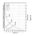
- FIG. 3A is a system response plot and FIG. 3B a Nichols plot of the controller of the present invention employed as the servo controller of FIG. 2A .
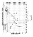
- FIG. 4A is a system response plot and FIG. 4B a Nichols plot of a comparative velocity feedback controller employed as the servo controller of FIG. 2A ;
- FIG. 5A is a system response plot and FIG. 5B a Nichols plot of a comparative PID controller employed as the servo controller of FIG. 2A ;
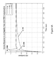
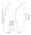
- FIG. 6A is a system response plot and FIG. 6B is a Nichols plot of a comparative quasi linear controller employed as the servo controller of FIG. 2A ;
- FIG. 7A is a system response plot and FIG. 7B a Nichols plot of the controller of the present invention including a phase compensating unit employed as the servo controller of FIG. 2A ;
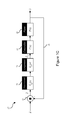
- FIGS. 8A and 8B provide respectively comparative response plots of a controller of the present invention alone and including a phase compensating unit comprising a single unstable pole and a stable zero and FIG. 8C discloses the open loop plots comprising and unstable pole and a stable zero.
- the feedback system 12 comprises the controller 10 , a plant 14 , a subtractor 16 , and a feedback path 18 which loops from the output of the plant 14 back to the input of the controller 10 .
- the plant 14 is a preexisting system that does not meet all the desired frequency- and time-domain design specifications of the feedback system 12 .
- the controller 10 is an additional system element that is added to the feedback system 12 to control the behavior of the plant 14 such that the design specifications are satisfied.
- the closed-loop controller 10 in accordance with an illustrative embodiment of the present invention is illustratively cascaded in series with the plant 14 to thereby control its behavior on the basis of a quasi-linear compensation technique as will be described herein below.
- û is the input signal to system
- ⁇ is the output signal from the plant 14
- ê is the error signal representing the difference between the input signal û and the output signal ⁇ as calculated by the subtractor 16 .
- C(s) and P(s) are the transfer functions of the controller 10 and the plant 14 , respectively.
- the output of the system ⁇ is fed back to the input of the subtractor 16 via the feedback path 18 .
- the controller 10 then processes the error ê, or difference between the input signal û and the output signal ⁇ , to modify the input to the plant 14 under control in a manner such that the plant meets the design performances.
- the design of the controller 10 of the present invention requires the plant 14 under consideration for compensation to be restricted to a certain class of plants having certain qualities.
- the plant 14 under consideration is a member of a family of invertible systems that are unstable, including a large number of industrial applications although in a particular embodiment the controller of the present invention could be used in combination with a stable or unstable plant compensated by a stable or unstable compensator in the open loop.
- the application of the controller 10 is restricted to a class of plants 14 which are linear time invariant, invertible, and strictly proper. More specifically, the plant 14 is invertible if it has no right-half plane zeroes, i.e.
- the definition of a minimum phase system is a system having neither zeros nor poles in the right-half complex plane. Accordingly, the plant 14 to which the controller 10 is applicable is limited to plants that include linear systems represented by transfer functions with stable or unstable poles and that the inverse has stable poles; linear systems represented by matrices of unstable transfer functions but the inverse of which is stable, for instance a plant having a determinant of the matrix of the transfer functions with roots located in the left-half complex plane; and linear systems for which the methods of classical control can guarantee stability for the use of high gains, including systems where the difference between the number of poles and zeros is greater than or equal to three.
- the controller 10 of the present invention may be applied in some instances to non-linear plants. Additionally, the controller 14 of the present invention may be applied to any number of plants 14 with high performance requirements including electrical systems, mechanical systems, industrial processes, military applications, flight control, power generation, computer servo systems, phase lock loops, and the like.
- the controller 10 of the present invention is generally employed in the feedback controlled system 12 to modify the behavior of the plant 14 so that it behaves in a specific desirable manner over time.
- the design objectives of the controller 10 include achieving arbitrarily fast and robust tracking, improved gain and phase stability margins, improved time domain measures and reduced rise times, and improved sensitivity of a variety of stable and unstable systems.
- the controller 10 achieves these performance measures simultaneously in the time-domain and the frequency-domain and does so without the tradeoffs normally associated with linear controllers.
- the controller 10 is derived from the group of controllers generally known as quasi-linear controllers.
- the quasi-linear controller 10 of the present invention is a controller comprising poles which depend in an appropriate way on its gain. Its advantage over linear controllers resides in that it is able to maintain the excess of poles over zeroes unaltered and allow for an increase in the loop transmission gain without jeopardizing the phase and gain stability margins.
- the design objective of the quasi-linear controller 10 of the present invention is to establish in an appropriate manner the way in which the poles of the controller 10 depend on its gain. It is generally known that a system's positioning of the poles in the complex S-plane influences performance. Poles that are positioned near to the j ⁇ -axis in the left half S-plane result in transient time domain responses that decay relatively slowly. In contrast, poles positioned in the left-half S-plane further away from the j ⁇ -axis correspond to more rapidly decaying time responses. It is also known that poles in the left-half complex S-plane lead to a stable system and poles in the right half complex S-plane lead to an unstable system.
- the quasi-linear controller 10 of the present invention automatically adapts to stability margins with the increase of gain, thereby attaining the performance benefits normally associated with high gain feedback.
- This approach will allow the feedback system 12 to attain improvements in the above mentioned performance measures, particularly, improved rise times, over prior art controllers.
- the controller 10 of the present invention operates by pushing the pole which wanders farther away from the j ⁇ -axis with the increase in gain by appropriately relating the poles of the controller 10 to its gain.
- This technique is contrasted with the pole-placement technique wherein a set of desirable poles is given and the design objective is to find the feedback gain so that the closed-loop system 12 obtains the desired transient response.
- the approach to the controller 10 design of the present invention is converse whereby the closed loop pole behavior is determined when the controller gain is increased unboundedly.
- the design objectives of the controller 10 take into account the time response such that the feedback gain has a dominant pole ⁇ 1 which responds to sufficiently rapid time response objectives while achieving sensitivity objectives.
- E( ⁇ ) be the sensitivity operator defines by [1+P( ⁇ )C( ⁇ )] ⁇ 1 .
- these sensitivity objectives include the minimum sensitivity conditions within a given bandwidth, for instance
- transfer functions of the present invention are described in terms of Laplace transforms, or in the s-domain, they may also be represented by their discrete Z-domain equivalents by choosing an appropriate sampling frequency which are generally known to be applicable to promote computational efficiency in digital implementations of the control system using standard digital control techniques such as digital signal processors, field-programmable gate arrays, application-specific integrated circuits, or the like.
- P ⁇ 1 (s) represents the inverse of the given plant 14 and J(s) approximates a real function in the manner now described.
- Such a design ensures that the sensitivity on the restricted frequency range
- the high gain filter J 1 (s) 20 is constructed so it satisfies the following conditions over a low frequency band:
- J 1 (s) can be realized as follows:
- inequality [6] ensures a possible and acceptable maximal sensitivity reduction by the high gain filter J 1 (s) 20 that is easily realizable
- >1/M may also be provided.
- the low pass filter J 2 (s) 22 may be provided for in the general form:
- J 2 (s) 22 may also be represented by ⁇ 2 k e jk ⁇ 2 , that is:
- the low pass filter J 2 (s) 22 may also be expressed by:
- Other alternative more generalized forms of J 2 (s) including:
- the frequency ⁇ 1 is chosen in a manner to obtain a fast time response e ⁇ 1 t
- the gain k 1 is selected to be sufficiently high to ensure the condition [5] is satisfied
- the gain k 1 along with the frequencies ⁇ 2i and the exponent k are selected to satisfy the condition [6] while ensuring that the controller C(s) 10 is strictly proper, in particular by choosing k to be greater than or equal to q.
- the design of the controller 10 also takes into account an intermediary frequency, ⁇ b ⁇ 2i for which the real part of the polar plot P( ⁇ )C( ⁇ ) lies to the right of the real value ( ⁇ 1+1/M) thus ensuring that [6] is satisfied as P( ⁇ )C( ⁇ ) is a decreasing function over the frequency range ⁇ > ⁇ b .
- Increasing the cutoff frequency of [10], and the exponent k if necessary, so that [6] is satisfied would allow to evaluate such a frequency ⁇ b .
- ⁇ b ⁇ 2i can be chosen to be the frequency for which
- the time response is essentially determined by the real and negative pole ⁇ 1 .
- ⁇ 1 could be replaced by ⁇ 10 , ⁇ 10 ⁇ 1 which is chosen to satisfy improved time domain performance objectives as long as the gain of the compensator at low frequency k 1 / ⁇ 1 is practically realizable.
- a higher gain k 1 will result in the choice of a higher intermediate value ⁇ b which will result in turn in a higher value of ⁇ 2i which are chosen to be superior to ⁇ b .
- the controller C(s) 10 is quasi-linear.
- the choice of ⁇ 2i could be reduced in various manners to improve implementation, such as a reduction in energy requirements.
- ⁇ 2 may be illustratively reduced in an alternative or additional manner by relaxing the constraint on the maximal sensitivity value M, or in other terms by allowing for a higher sensitivity value M.
- ⁇ 2 and the exponent k if necessary, is chosen so that the Nyquist plot of
- does not intersect the circle described by (X+1)+Y (1/M) 2 where X and Y are the real and the imaginary axis of the same Nyquist plot, and ⁇ 2 is bigger than or equal to a frequency ⁇ b > ⁇ 1 for which
- ⁇ b could be defined as the frequency beyond which
- the sensitivity circle M could be represented on the Nichols chart by representing the graph 20 log [cos ⁇ + ⁇ ((cos 2 ⁇ ) ⁇ 1+1/M 2 )] if cos 2 ⁇ >(1 ⁇ 1/M 2 ).
- the design of ⁇ 2 could proceed in a simpler manner.
- the diagram of J ⁇ 1 (s) could be plotted, the classical M-circles (constant magnitudes of the closed loop) representing this time the sensitivity circles.
- FIG. 1C there is disclosed an illustrative embodiment of a compensating unit 26 that is employed to improve the feedback system 12 metrics in the case of the system 12 operating outside of its proper operating range.
- the compensating unit 26 will adjust the phase of the system 12 when ⁇ 2 is reduced to improve implementation, in particular, when ⁇ 2 is reduced in order to reduce the energy associated with a high ⁇ 2 .
- a decrease in ⁇ 2 has an effect of increasing the temporal response of the system 12 , in particular the rise times, which can be compensated for by the addition of the compensating unit 26 , G c1 (s), which is illustratively cascaded in front of the controller 10 C(s).
- the compensating unit 26 illustratively comprises a chain of lead/lag compensator elements as a n phase-lead/phase lag compensator as is generally known in the art, and may take the transfer function form given by:
- the poles and zeros of the compensating unit 26 are chosen in a manner such that the poles of the system 12 are shifted to the left to counteract both the increases in the system time responsiveness and system instabilities caused by the phase lagging effect introduced by a reduction in ⁇ 2 .
- ⁇ 2 may be reduced while the advantages provided for by the controller 10 , such as fast rise times, are preserved.
- the exact locations of the poles and zeros are selected based upon the characteristics of the controller 10 , such as ⁇ 2 and the gain k 1
- the gain of the system 12 is controlled by the gain k c of the compensating unit 26 and the gain k 1 of the high gain filter J 1 (s) 20 , both of which may be independently adjusted to tune the system 12 .
- phase lead/lag compensator has been shown to illustratively comprise the compensating unit 26 , G c1 (s), a phase lead compensator, or any phase compensating technique that introduces a phase lead or the like may be employed to correct the phase lag introduced by a reduction in ⁇ 2 .
- a lag compensation introduced by the compensating unit 26 may also be used to increase the low-frequency gain for improved disturbance rejection or to decrease the high-frequency gain for improved noise rejection or augmented gain margin that may also have been caused by the decrease in ⁇ 2 .
- the lead/lag compensator can be used in addition to an unstable phase network G c2 (s) 28 , illustratively comprised of at least an unstable pole and a stable zero, which can be adjusted, as will be seen below, to improve response in the time domain thereby improving the overall performance of the resultant controlled system.
- G c2 (s) 28 illustratively comprised of at least an unstable pole and a stable zero, which can be adjusted, as will be seen below, to improve response in the time domain thereby improving the overall performance of the resultant controlled system.
- the design method can be applied to the open loop unstable poles, that is the poles of the plant P(s), or those of the compensator C(s), or of both, can be unstable.
- the above can be incorporated directly into J 2 (s) which can then be described using the following generalized forms:
- stability and sensitivity goals can be achieved using an open loop that includes unstable poles.
- These poles can exist in the plant P(s), in the compensator C(s) or in both.
- the following shows the principles of a graph method ensuring the encirclement of the critical point when a stable zero z and an unstable pole p is added, e.g. for z ⁇ p ⁇ 1 .
- the condition of non-encirclement of the M sensitivity circle can also be satisfied by choosing ⁇ b as in the minimum phase case.
- the phase of J( ⁇ b ) can be made close to ⁇ 90° as ⁇ b can be chosen so that:
- the compensating unit 26 may be implemented in both analog and digital control forms, for instance in the Laplace and Z-transform domains, for application on a digital signal processors or the like.
- the transfer function of a high gain filter J 1 (s) 20 , and the transfer function of the low pass filter J 2 (s) 22 may be represented in the Z-domain for digital implementation using standard digital control techniques as are generally known in the art.
- J(s) may be decomposed into a sum using the residue theorem, or as is generally known as Cauchy's Residue Theorem, assuming that:
- the repeated poles contribute to a series expansion of the transfer function with positive or negative coefficients.
- Each of these elements of the series expansion contributes separately to the overall time response and the choice of repeated poles may improve the fine tuning of the overall time response. Additionally, it is possible to extend the region of convergence of the logarithmic integral function in the whole complex plane by analytic continuation in the case of poles located outside the region of convergence
- the controller 10 may equally be employed as part of feedback system 12 to stabilize an unstable plant 14 .
- the application of the controller 10 may thus be further extended according to the following design considerations.
- the frequency ⁇ a such that P(s) is holomorphic for
- J 1 (s) is a high gain filter 20 having a fast time response
- J 2 (s) is a low pass filter 22 acting at high frequencies such that the controller 10 is strictly proper
- [P( ⁇ )H ⁇ 1 ( ⁇ )] is holomorphic.
- the sensitivity objectives can be reached by designing J 1 (s) and J 2 (s) such that [32] and [33] above are satisfied.
- J 1 (s) can have the form:
- ⁇ 1 is chosen in a manner to obtain a fast time response e ⁇ 1 t .
- ⁇ 1 could be replaced by ⁇ 10 , ⁇ 10 ⁇ 1 which is chosen to satisfy improved time domain performance objectives as long as the gain of the compensator at low frequency k 1 is practically realizable and is chosen to be sufficiently high to ensure the condition [32] is satisfied.
- the gain k 1 along with the frequency ⁇ 2 (satisfying ⁇ 2 > ⁇ e ) and the exponent k are adjusted to satisfy the condition [33].
- the design of the controller 10 also takes into account an intermediary frequency ⁇ b for which
- H ⁇ ( s ) c ( s + s 0 ) q ⁇ P 1 (s) such that as s ⁇ for a certain value of s 0 and a certain c, H(s) has the same behavior as P 2 (s) at high frequency ⁇ > ⁇ e .
- ⁇ 1 is preferably chosen to be superior or equal to ⁇ d ; defining ⁇ a for
- controller design follows the same procedure as that undertaken for a minimum phase plant as described hereinabove, according to the transfer function:
- J 1 ⁇ ( s ) k 1 ⁇ [ ⁇ 1 ( s + ⁇ 1 ) ] and J 2 (s) 22 has the form
- the low pass filter J 2 (s) 22 could have a more general form as illustratively described in equation [6] hereinabove.
- the gain k 1 , the frequency ⁇ 2 , and the parameter k are adjusted to satisfy conditions [33] and [34]. For example:
- k 1 2 ⁇ max ⁇ [ inf ⁇ [ P ⁇ ( ⁇ ) ⁇ H - 1 ⁇ ( ⁇ ) ] ⁇ ( 1 + 1 ⁇ ) ⁇ ⁇ for ⁇ ⁇ ⁇ ⁇ ⁇ 1 , inf ⁇ [ P ⁇ ( ⁇ ) ⁇ H - 1 ⁇ ( ⁇ ) ] ⁇ ( 1 + 1 M ) ⁇ ⁇ for ⁇ ⁇ all ⁇ ⁇ ⁇ ] [ 40 ]
- the frequency ⁇ 2 and the parameter k are adjusted so that
- the choice of ⁇ 2 may be reduced in the manner as has been described hereinabove.
- the controller 10 may be represented as a rational transfer function, it can therefore be easily implemented in the feedback controlled structure as illustrated in FIG. 1A , in an offline manner. Moreover, since the controller 10 is linear and Nyquist stable for all large gains k 1 , the value of k 1 may be increased, even on-line, thus improving the performance of the feedback system 12 during functioning if the variations of k 1 lie within a sector and an appropriate criteria such as the circle criteria is satisfied.
- the plant 14 to be controlled is unstable and the controller 10 designed according to the approach described hereinabove.
- the plant 14 is represented by the following transfer function:
- ⁇ 1 5 is selected.
- the plant P(s) 14 can be reduced to two transfer functions of the form:
- the plant 14 in accordance with this exemplary embodiment presents a significant obstruction to high performance by a linear feedback. Its excess of poles over zeros limits the increase of the controller gain if the dynamic compensation order is kept at acceptable low levels, affecting performance and stability which call for increased gain. Quasi-linear compensation can be applied to achieve high performance simultaneously in the time and frequency domains. Note that
- ⁇ a 1 and in this particular case, ⁇ c can take any value e.g. 1.
- a compensating unit 26 as has been described hereinabove may be employed to correct phase shifts introduced by a controller 10 used to control unstable plants P(s) 14 comprising a reduction in ⁇ 2 .
- C ⁇ ( s ) ( s + 2 ) 2 ⁇ k 1 ⁇ [ ⁇ 1 ( s + ⁇ 1 ) ] ⁇ [ ⁇ 2 ( s + ⁇ 2 ) ] k [ 44 ] is applied such that the condition k>1 ensures that the controller 10 is strictly proper.
- the parameters k 1 , ⁇ 2 ,k can be chosen to ensure that for
- P(s) incorporates at least one right half plane zeros, they could be included in the unstable part P 2 (s) as long as precautions are taken to ensure that C(s) is strictly proper and that
- is still bounded below.
- the numerator (s+1) is replaced by (s ⁇ 5) in equation 43, it would still follow that
- the lower bound on sensitivity ⁇ 1 can be achieved over the limited frequency range ⁇ 1 . Otherwise, only a sensitivity bound smaller than M on all frequencies can be achieved. Additionally, care should be taken to ensure accordance with the Nyquist criteria.
- an unstable pole 1/(s ⁇ p) could be represented by B(s)/(s+p) where B(s) is an all-pass network that will rotate the Nyquist curve in a positive direction. Special care should than be given to stability and sensitivity considerations as well as to time response considerations.
- J(s) comprising the product of a high gain filter J 1 (s) having a gain sufficient that
- the hard disk drive servo system 34 for a hard disk drive 36 comprises a magnetic recording platter 38 for storing data on the surface thereof in sectors and tracks wherein the tracks are concentric circles and the sectors are pie-shaped wedges on a track, and a drive motor 40 for spinning the platter 38 . Additionally, a magnetic head 42 for writing and reading information to and from the platter 38 is provided and an arm rotary actuator 44 comprising a permanent magnet DC motor and an amplifier (not shown) which is used to position an arm 46 comprising a suspension arm 48 for long range seeking.
- a slider device 50 connected to the suspension arm 48 and comprising a flexure or metal spring can be provided to enable the head 42 connected thereto to float above the platter 38 surface for micro-tracking.
- the hard disk drive servo system 34 further comprises a servo controller 52 for controlling the position of the magnetic head 40 relative to a track located on the surface of the platter 38 .
- the platter 38 employed in the hard disk drive 36 is generally known to rotate at frequencies of 5,400 or 5,900 or 7,200 Rotations-Per-Minute (RPM) while platters 38 used in servers rotate at frequencies of 10,000 or 15,000 RPM.
- positioning of the head 42 in precision alignment with respect to a track on the surface of the platter 38 is generally known to be undertaken in the following described manner.
- An input reference track and sector position represented by the Laplace transform R(s) as requested by a host computer (not shown) is inputted to the subtractor 16 which outputs a position error E(s).
- the position error E(s) is calculated by subtracting an actual position reading Y(s), as monitored by the head 38 itself, from the input reference position R(s).
- the error E(s) between the actual position Y(s) and the reference position R(s) is then fed into the controller 52 which is tasked to generate drive signals for the actuator 44 such that the arm 46 , and ultimately the head 42 , is moved to the desired reference position R(s).
- the servo controller 52 will control the acceleration of the head 42 due to a torque generated by the actuator 44 on the arm 46 .
- the controller 52 will also ensure that the position of the head 42 remains over the center of the requested track.
- a control objective of the servo controller 52 is to accurately and precisely position the head 42 from one track to another during track seek in the shortest time possible. Since the time for positioning the head 42 over the correct track has a significant impact on the performance of the hard disk drive 36 , the quicker the head 42 can be moved between tracks during seeking, the faster information can be stored or retrieved.
- An additional control objective of the servo controller 52 involves regulating the position of the head 42 during track following.
- the sensitivity of the position of the head 42 to external disturbances is also an important design consideration, especially as hard disks 36 are being employed in mobile computing applications such as in laptops or handheld devices where disturbances from shock and vibration tend to effect the position of the head 42 . Additional disturbances to the system also include wear, wobble due to the spindle bearings, resonant oscillations generated by the actuator, measurement noise, and the like.
- the transfer function P HD (s) of the actuator 44 and the permanent magnet DC motor, the linear amplifier, the arm 48 and the slider 50 is given in accordance with an exemplary embodiment of the present invention by:
- the performance of the hard disk drive servo system 34 as described by the above model equations is examined in comparison with a controller 10 of the present invention employed as the servo controller 52 to that of a servo controller 52 employing a variety of other control methods including PID control and velocity feedback control.
- the stability margins, sensitivities, the steady-state error and transient responses including rise times and settling times of the system are examined when the gain of the controller 52 is varied from 50 to 1000.
- the performances are examined by their representations in the time domain by a step response time domain plot and in the frequency domain by a Nichols plot.
- the controller of the present invention is able to achieve arbitrarily high performances in the time and frequency domains, and in a simultaneous manner.
- the system rise time is approximately 0.0109 seconds and is significantly faster than the rise times attainable by other types of controllers.
- the frequency domain performance of the system demonstrates stability margins with a gain margins varying from 200 dB to 106 dB as the gain is increased, and higher than the gain margins provided for by the other types controllers.
- the phase margin is negligibly affected and remains at 90 degrees between the gain increase, a direct consequence of the control employed.
- the rise time is the time necessary for the signal to rise from 10% to 90% of its final value and the stabilizing time is the time necessary for the signal to reach 95% of its final value.
- the time response can be improved by choosing a larger value of ⁇ d ( ⁇ desired), which can also affect the invested energy in the system (that is, the area between the square of the frequency response and the ⁇ axis).
- the transient response and stability of the hard disk drive servo system 34 when the servo controller 52 is a velocity feedback control is illustrated via step response and Nichols plots.
- the frequency domain performance of the system demonstrates a gain margin of 29.4 dB as the gain is increased, while the phase margin is minimally affected and remains at 48.4 degrees.
- the transient response and stability of the hard disk drive servo system 34 when the servo controller 52 is a PID controller is illustrated via step response and Nichols plots.
- the frequency domain performance of the system demonstrates a gain margin that remains stable at approximately 54 dB as the gain is increased, while the phase margin remains between 45 and 87.1 degrees.
- the transient response and stability of the hard disk drive servo system 34 when the servo controller 52 is an existing quasi-linear controller is illustrated via step response and Nichols plots.
- the frequency domain performance of the system demonstrates stability margins with a gain margin at approximately 90 dB as the gain is increased, while the phase margin is negligibly affected and remains at 90 degrees between this gain increase, a direct consequence of a quasi-linear compensation technique.
- the compensator of the present invention provides for significantly improved rise times and settling times, improved gain and phase margins, and improved sensitivity to external disturbances in comparison to other types of controllers when employed as a servo controller for a hard disk 36 . It is generally known that the largest delay element of hard drive disk access times is the seek time, a metric which best represents positioning performance.
- FIG. 7A and FIG. 7B in addition to FIG. 2B , the transient response and stability of a controller of the present invention (as developed above for controlling the read-write head positioning actuator 44 of a hard disk drive 36 and in reference to FIGS. 2A and 2B ) in combination with a lead/lag compensator 26 is exemplified via step response and Nichols plots.
- the step response plot of FIG. 7A illustratively shows the response times of the system 12 comprising various phase network parameters.
- the time response curve 50 illustrates the response time in light of the parameters mentioned hereinabove.
- the gains k c and k 1 whose products do not necessarily result in a linear gain scaling of the system 12 , can be independently tuned to optimize the system response.
- FIG. 8A and FIG. 8B in addition to FIG. 2B , a comparative assessment of a controller 10 of the present invention (again, as developed above for controlling the read-write head positioning actuator 44 of a hard disk drive 36 and in reference to FIGS. 2A and 2B ) alone ( FIG. 8A ) and in combination with a phase network 28 comprising a single unstable pole and zero is provided.
- appropriate selection of the pole and zero (illustratively respectively 0.15 and 2) for the phase network 28 can improve time domain response while improving both gain margin, which is illustratively improved from about 7.3 dB to 14.3 dB, and phase margin, which is illustratively improved from 44.3 to 68.1 degrees (see FIG. 8C ).
- the controller of the present invention provides a significant improvement in rise time over other types of controllers which translates into a significant performance increase related to reduced seek and access times.
- the controller of the present invention provides other advantages when illustratively employed as part of a hard disk drive servo system 34 .
- the structure of the controller 10 in accordance with an illustrative embodiment described hereinabove is simple and low-order thus eliminating the requirement of complex and powerful microprocessors for its implementation, as would be required for complex higher-order controllers.
- the consequences of this simplicity translates into a reduction of hard disk drive unit hardware costs as well as a reduction in computational delays associated with high-order controllers further resulting in improved hard disk access times.
- the controller of the present invention uses of high cost vibration reducing mechanical components such as spindles, ball bearings, disk platters, and special vibration reducing material casings or the like to substituted for cheaper higher vibration generating components as the controller of the present invention is able to compensate for an increase in vibration disturbances. Still further, improved position accuracy allows for a hard disk drive comprising higher track density on a disk platter.
- a hard disk drive platter 38 controlled by a servo system 34 employing a controller 10 of the present invention would be able to spin at lower rotational speeds to achieve the same access times thus benefiting from reduced energy consumption, reduced vibration generation resulting from a higher rotation of the platter 38 , and increased mean time between disk failure.
Landscapes
- Physics & Mathematics (AREA)
- General Physics & Mathematics (AREA)
- Engineering & Computer Science (AREA)
- Automation & Control Theory (AREA)
- Feedback Control In General (AREA)
Abstract
when |ω|≦ω1 and |1+J(ω)|>1/M for all ω wherein ω1 is selected to obtain a desired time response, and a low pass filter J2(s) selected such that |1+J(ω)|>1/M for all ω and J(s) is strictly proper, wherein ε<1 and M>1 and ε and M are selected to meet a desired sensitivity requirement. An error signal e is calculated comprising the difference between the system input signal u and the plant output signal y, and the error signal modified according to the transfer function C(s)=P−1(s)J1(s)J2(s) and inputting the error signal into the plant. The system and method can be extended to unstable invertible plants. A global sensitivity bound M≧1 could also be achieved for plants including right half planes zeros. The system and method are shown applied to a read-write head positioning actuator of a hard disk drive, but can be applied equally to other systems such as electrical systems, mechanical systems, industrial processes, military applications, flight control, power generation, computer servo systems, phase lock loops and the like.
Description
when |ω|≦ω1 and |1+J(ω)|>1/M for all ω wherein ω1 is selected to obtain a desired time response, and a low pass filter J2(s) selected such that |1+J(ω)|>1/M for all ω and C(s)=P−1(s)J(s) is strictly proper, wherein ε<1 and M>1 and ε and M are selected to meet a desired sensitivity requirement, calculating an error signal e comprising the difference between the system input signal u and the plant output signal y, and modifying the error signal according to the transfer function C(s)=P−1(s)J1(s)J2(s) and inputting the error signal into the plant.
when |ω|≦ω1 and |1+J(ω)|>1/M for all ω and wherein ω1 is chosen to obtain a required time response, and a low pass filter J2(s) selected such that |1+J(ω)|>1/M for all ω and C(s)=P−1(s)J(s) is strictly proper. The error signal is modified according to the transfer function C(s)=P−1(s)J1(s)J2(s) prior to input into the plant.
when |ω|≦ω1 and |1+J(ω)|>1/M for all ω and wherein ω1 is chosen to obtain a required time response, and a low pass filter J2(s) selected such that |1+J(ω)|>1/M for all ω and C(s)=P−1(s)J(s) is strictly proper, wherein the error signal is modified according to the transfer function C(s)=P−1(s)J1(s)J2(s) prior to input into the plant.
ŷ=PCê [1]
ê=û−ŷ [2]
where the signals û, ŷ and ê represent the Laplace transforms of the corresponding time domain functions u(t), y(t) and e(t) respectively. In particular, û is the input signal to system, ŷ is the output signal from the
C(s)=P −1(s)J(s) [3]
Where P−1(s) represents the inverse of the given
C(s)=P −1(s)J(s)=P −1(s)J 1(s)J 2(s) [4]
wherein P−1(s) is the inverse transfer function of the plant P(s) 24, J1(s) is the transfer function of a
In a case where the low pass filter J2(s) 22 has p repeated values ω2i, (i=1 . . . p) of order ri and qj (j=1, 2, . . . q) distinct values, such that Σri+q=k, the low pass filter J2(s) 22 may also be expressed by:
Other alternative more generalized forms of J2(s) including:
If J1(s) 20 is denoted by k1ρ1eJθ
For the low pass filter J2(s) 22 given by the form described in equation [8], the following condition for the choice of frequencies ω2i is given by:
For the low pass filter J2(s) 22 and given by the form described in equation [9], the following condition for the choice of frequencies ω2i is given by:
where zi and pi are respectively the zeros and the poles of the compensating
the condition:
translates into:
while the gain k1 is also increased to satisfy the conditions:
Real{J(ωf)}≧−1+1/M and |Im{J(ωf)}|=1/M for some ωf,ω1≦ωf<ω2
This ensures one encirclement of the critical point (−1,0) as |J(ω)| is a decreasing function of ω for ω>ω1, and guarantees the stability of the closed loop while the open loop is unstable. The added condition:
arg{J(ω)}>−π+arctan(M/(M−1)) for ω>ωf
could guarantee that the M sensitivity circle is still encircled. Note that the added phase of the unstable pole—stable zero combination in the compensator contributes a phase varying between −180° and 0°.
|P(ωb)C(ωb)|≦1−1/M for ω≧ωb
and
|k·arctan(ωb/ω2)+arctan(ωb/ω1)|<π/2
and ensuring that the contributed phase of (s+z)/(s−p) satisfies:
arg{(jω b +z)/(jω b −p)}>−π+arcsin(1/M).
with K=[(s+ω1)J(s)]s=−ω
j≠i which translates into the following inverse Laplace transform:
and the z-transform given by:
Now, assuming that J1(s)=(K/(s+ω1)) and J2(s)=[ω2/(s+ω2)]k, then:
By letting i=k−1, then:
and:
K=[(s+ω 1)J(s)]s=−ω
and thus J(s) translates into the inverse Laplace transform:
or, by taking into account that the z-transform of e−annk is
where the Logarithmic integral function Li is defined within the region of convergence by
then the z-transform of J(s) becomes:
Now, assuming that J2(s) has p repeated values ω2i, (i=1 . . . p) of order ri and qi(j=1, 2, . . . q) distinct values, such that Σri+q=k,
and J(s)=J1(s)J2(s) then:
the inverse Laplace transform of J(s) is given by:
and the z-transform of J(s) is thus given by:
P(s)=P 1(s)P 2(s) [28]
such that when s→∞ for a given value of s0 and constant c, P2(s) approaches a function based on the form:
such that H(s) has the same behavior as P(s) at high frequency. By selecting the frequency ωa such that P(s) is holomorphic for |s|>ωa and the frequency ωc above which P(s) and H(s) have the same high frequency behavior, i.e. ∥P(s)((H(s))1∥<α<1, |s|>ωc where α is a value inferior to unity and sufficiently small to ensure that M(1−α)>1, the design of the
is satisfied. Note that the condition in equation [33] may also be satisfied by increasing the value of ω2 as needed. i.e. as k1 is increased, the expression k1[ω1/(s+(1+k1)ω1)] approaches unity, while the expression [1−[ω2/(s+ω2)]k], approaches zero as ω2 increases. This gain-pole dependency is consistent with the quasi-linear property of the feedback compensation. Note that the equation at [34] has been derived from BENSOUSSAN, David, ZAMES, Georges, “Multivariable Feedback, Sensitivity and Decentralized Control”, IEEE Transactions on Automatic Control, vol. AC-28, n° 11, November 1983, which is incorporated herein by reference in its entirety.
for high bandwidth ω>ωe, the sensitivity objectives can be reached by designing J1(s) and J2(s) such that [32] and [33] above are satisfied.
and J2(s) the form:
wherein the frequency ω1 is chosen in a manner to obtain a fast time response e−ω
all while ensuring that condition [33] is satisfied and for which the modulus of P(ω)C(ω) is a decreasing function over the frequency range ω>ωb. Consequentially, the time response is essentially determined by the real and negative pole ω1 which is chosen to satisfy the time domain performance objectives. Note, although J(ω) has been chosen to be a positive function in the frequency domain ω<ω1 it could be ultimately, i.e. at a high enough frequency, located to the right of the real line (−1+1/M) in the complex plane or even simply lie outside the sensitivity circle M.
for high frequencies ω>ωe, the
(s) such that as s→∞ for a certain value of s0 and a certain c, H(s) has the same behavior as P2(s) at high frequency ω>ωe.
where J(s)=J1(s)J2(s) and where J1(s) is a
and J2(s) 22 has the form
which satisfies ω2>ωe. In accordance with an alternative embodiment of the present invention, the low pass filter J2(s) 22 could have a more general form as illustratively described in equation [6] hereinabove. The design of the
P(ω)H −1(ω)=(s+s 0)q P 1 −1(s) [39]
such that |J(ω)|, which is essentially controlled by J1(ω) and the Nyquist diagram, remains to the right of the real value −1+1/M all while satisfying [33]. The gain k1, the frequency ω2, and the parameter k are adjusted to satisfy conditions [33] and [34]. For example:
and that at high frequencies, α=0. In other words, ωa=1 and in this particular case, ωc can take any value e.g. 1.
is applied such that the condition k>1 ensures that the
when |ω|23 ω1 smaller than zi and |1+J(ω)|>1/M for all ω provided the condition of encirclements of the Nyquist criterium is respected, wherein ω1 is selected to obtain a desired time response, and a low pass filter J2(s) selected such that |1+J(ω)|>1/M for all ω and C(s) is strictly proper, wherein ε<1 and M>1 and ε and M are selected to meet a desired sensitivity requirement.
wherein M is the inertia of the
and the model for the
Still referring to
Additionally, the
wherein ωn is the under damped angular frequency of the system, and ξ is the damping ratio. Employing realistic values of ξ=0.3 and ωn=18.85×10³ rad/s, the
| Comparative Table at K = 200 |
| GM | PM | tr | ts | E(ω = ωi) |
| (dB) | (deg) | (sec) | (sec) | ωi = 5 | ωi = 25 | ||
| Compensator | 106 | 90.3 | 0.0109 | 0.0149 | 0 | 0.02 |
| of Present | ||||||
| Invention | ||||||
| PID | 54.8 | 87.1 | 0.0416 | 0.0578 | 0.01 | 0.2 |
| Compensator | ||||||
| Velocity | 29.4 | 48.4 | 0.0493 | 0.167 | 0 | 0 |
| Feedback | ||||||
| Compensator | ||||||
| Quasi-linear | 90.6 | 90.8 | 5.12 | 6.95 | 0.98 | 1 |
| Compensator | ||||||
Claims (27)
C(s)=P −1(s)J 1(s)J 2(s)
C(s)=H −1(s)J 1(s)J 2(s)
C(s)=P −1(s)J 1(s)J 2(s)
C(s)=H −1(s)J 1(s)J 2(s)
Priority Applications (1)
| Application Number | Priority Date | Filing Date | Title |
|---|---|---|---|
| US13/217,861 US8831755B2 (en) | 2010-08-25 | 2011-08-25 | System and method for feedback control |
Applications Claiming Priority (4)
| Application Number | Priority Date | Filing Date | Title |
|---|---|---|---|
| US37687210P | 2010-08-25 | 2010-08-25 | |
| US41003910P | 2010-11-04 | 2010-11-04 | |
| US42329010P | 2010-12-15 | 2010-12-15 | |
| US13/217,861 US8831755B2 (en) | 2010-08-25 | 2011-08-25 | System and method for feedback control |
Publications (2)
| Publication Number | Publication Date |
|---|---|
| US20120053705A1 US20120053705A1 (en) | 2012-03-01 |
| US8831755B2 true US8831755B2 (en) | 2014-09-09 |
Family
ID=45698231
Family Applications (1)
| Application Number | Title | Priority Date | Filing Date |
|---|---|---|---|
| US13/217,861 Active 2033-04-05 US8831755B2 (en) | 2010-08-25 | 2011-08-25 | System and method for feedback control |
Country Status (2)
| Country | Link |
|---|---|
| US (1) | US8831755B2 (en) |
| WO (1) | WO2012024802A1 (en) |
Cited By (1)
| Publication number | Priority date | Publication date | Assignee | Title |
|---|---|---|---|---|
| US20180067086A1 (en) * | 2016-09-08 | 2018-03-08 | Linestream Technologies | Method for automatically identifying resonance |
Families Citing this family (16)
| Publication number | Priority date | Publication date | Assignee | Title |
|---|---|---|---|---|
| CA2727794A1 (en) | 2008-06-11 | 2009-12-17 | Qinghui Yuan | Auto-tuning electro-hydraulic valve |
| US8467888B2 (en) * | 2009-06-05 | 2013-06-18 | The Mathworks, Inc. | Automated PID controller design |
| JP5707129B2 (en) * | 2010-12-28 | 2015-04-22 | Thk株式会社 | Motor control device, motor control method, and control program |
| CN103036529B (en) | 2011-09-29 | 2017-07-07 | 株式会社大亨 | Signal processing devices, filters, control circuits, inverters and converter systems |
| DK2575252T3 (en) | 2011-09-29 | 2018-10-08 | Daihen Corp | Signal processor, filter, power converter for power converter circuit, connection inverter system and PWM inverter system |
| US9886008B1 (en) | 2013-06-07 | 2018-02-06 | The Mathworks, Inc. | Automated PID controller design, using parameters that satisfy a merit function |
| US9280144B2 (en) | 2013-10-08 | 2016-03-08 | Jonix Llc | Compensation for canonical second order systems for eliminating peaking at the natural frequency and increasing bandwidth |
| US9240199B2 (en) * | 2014-03-12 | 2016-01-19 | Avago Technologies General Ip (Singapore) Pte. Ltd. | Systems and methods for distortion characterization |
| US10451623B2 (en) | 2016-03-29 | 2019-10-22 | Nanodetection Technology, Inc. | System for chemiluminescence-based detection of methicillin-resistant Staphylococcus aureus |
| JP6731666B2 (en) | 2017-12-19 | 2020-07-29 | 国立大学法人神戸大学 | Design support device, design support method, and design support program |
| CN110500190A (en) * | 2018-05-17 | 2019-11-26 | 康明斯有限公司 | The adaptive engine speed gain of industrial machine |
| CN109946979B (en) * | 2019-04-25 | 2022-03-22 | 广东省智能机器人研究院 | Self-adaptive adjusting method for sensitivity function of servo system |
| CN110737193B (en) * | 2019-09-19 | 2021-11-23 | 中建材创新科技研究院有限公司 | Synchronous algorithm control system for controlling multiple shafts through virtual shaft |
| US11314232B2 (en) * | 2020-09-15 | 2022-04-26 | Applied Materials, Inc. | Frequency response diagnostics for characterizing servo controlled mechanisms |
| CN112650264B (en) * | 2020-12-18 | 2021-12-10 | 北京航空航天大学 | A robust composite control method for control moment gyro frame system |
| KR102806887B1 (en) * | 2023-11-07 | 2025-05-15 | 주식회사 동운아나텍 | Apparatus and method for calculating frequency response of ball bearing type actuator plant |
Citations (12)
| Publication number | Priority date | Publication date | Assignee | Title |
|---|---|---|---|---|
| US4639854A (en) | 1983-02-01 | 1987-01-27 | Sanyo Denki Co. Ltd. | High gain feedback control system |
| US5276569A (en) | 1991-06-26 | 1994-01-04 | Digital Equipment Corporation | Spindle controller with startup correction of disk position |
| US5625551A (en) | 1993-12-28 | 1997-04-29 | Canon Kabushiki Kaisha | Feedback controller |
| US5726879A (en) * | 1994-03-14 | 1998-03-10 | Canon Kabushiki Kaisha | Control apparatus, a stage apparatus and a hard disk servo writer apparatus including a robust stabilizing compensator |
| US5732373A (en) | 1995-04-21 | 1998-03-24 | Nsk, Ltd. | Control apparatus with stability compensator for electric power steering system |
| US6204988B1 (en) | 1998-08-24 | 2001-03-20 | Western Digital Corporation | Disk drive capable of autonomously evaluating and adapting the frequency response of its servo control system |
| US20020111758A1 (en) | 2000-10-18 | 2002-08-15 | Qing-Guo Wang | Robust process identification and auto-tuning control |
| US20020144163A1 (en) * | 2000-10-10 | 2002-10-03 | Ryan Goodfellow | System and method for highly phased power regulation using adaptive compensation control |
| US6629089B1 (en) * | 2000-09-29 | 2003-09-30 | Cirrus Logic, Inc. | Artificial neural network voice coil motor controller |
| US20030199997A1 (en) | 2002-04-18 | 2003-10-23 | Zhiqiang Gao | Scaling and parameterizing a controller |
| US20040030414A1 (en) * | 1999-09-10 | 2004-02-12 | Koza John R. | Method and apparatus for automatic synthesis of controllers |
| US20090027118A1 (en) | 2007-07-25 | 2009-01-29 | Andersen Jack B | Digital PWM Amplifier Having a Low Delay Corrector |
-
2011
- 2011-08-25 WO PCT/CA2011/050517 patent/WO2012024802A1/en not_active Ceased
- 2011-08-25 US US13/217,861 patent/US8831755B2/en active Active
Patent Citations (14)
| Publication number | Priority date | Publication date | Assignee | Title |
|---|---|---|---|---|
| US4639854A (en) | 1983-02-01 | 1987-01-27 | Sanyo Denki Co. Ltd. | High gain feedback control system |
| US5276569A (en) | 1991-06-26 | 1994-01-04 | Digital Equipment Corporation | Spindle controller with startup correction of disk position |
| US5625551A (en) | 1993-12-28 | 1997-04-29 | Canon Kabushiki Kaisha | Feedback controller |
| US5726879A (en) * | 1994-03-14 | 1998-03-10 | Canon Kabushiki Kaisha | Control apparatus, a stage apparatus and a hard disk servo writer apparatus including a robust stabilizing compensator |
| US5732373A (en) | 1995-04-21 | 1998-03-24 | Nsk, Ltd. | Control apparatus with stability compensator for electric power steering system |
| US6204988B1 (en) | 1998-08-24 | 2001-03-20 | Western Digital Corporation | Disk drive capable of autonomously evaluating and adapting the frequency response of its servo control system |
| US7117186B2 (en) * | 1999-09-10 | 2006-10-03 | John R. Koza | Method and apparatus for automatic synthesis of controllers |
| US20040030414A1 (en) * | 1999-09-10 | 2004-02-12 | Koza John R. | Method and apparatus for automatic synthesis of controllers |
| US6629089B1 (en) * | 2000-09-29 | 2003-09-30 | Cirrus Logic, Inc. | Artificial neural network voice coil motor controller |
| US7007176B2 (en) * | 2000-10-10 | 2006-02-28 | Primarion, Inc. | System and method for highly phased power regulation using adaptive compensation control |
| US20020144163A1 (en) * | 2000-10-10 | 2002-10-03 | Ryan Goodfellow | System and method for highly phased power regulation using adaptive compensation control |
| US20020111758A1 (en) | 2000-10-18 | 2002-08-15 | Qing-Guo Wang | Robust process identification and auto-tuning control |
| US20030199997A1 (en) | 2002-04-18 | 2003-10-23 | Zhiqiang Gao | Scaling and parameterizing a controller |
| US20090027118A1 (en) | 2007-07-25 | 2009-01-29 | Andersen Jack B | Digital PWM Amplifier Having a Low Delay Corrector |
Non-Patent Citations (6)
| Title |
|---|
| Bensoussan et al., Application of quasi-linear feedback to the control of a hard disk drive servo system, IEEE ISIE 2006, Jul. 9-12, 2006, Montréal, Canada, 307-309. |
| Bensoussan et al., Arbitrarily fast tracking feedback systems for a class of nonlinear plants, Proceedings of the 17th IFAC World Congress, 2008, 12200-12205. |
| Bensoussan, Decentralized control and sensitivity reduction of weakly coupled plants, Int. J. Control, 1984, vol. 40, No. 6, 1099-1118. |
| Bensoussan, Sensitivity reduction in single-input single-output systems, Int. J. Control, 1984, vol. 39, No. 2, 321-335. |
| International Search Report of Application No. PCT/CA2011/050517, Nov. 8, 2011. |
| Kelemen et al., On the design, robustness, implementation and use of quasi-linear feedback compensators, Int. J. Control, Apr. 15, 2004, vol. 77, No. 6, 527-545. |
Cited By (2)
| Publication number | Priority date | Publication date | Assignee | Title |
|---|---|---|---|---|
| US20180067086A1 (en) * | 2016-09-08 | 2018-03-08 | Linestream Technologies | Method for automatically identifying resonance |
| US10184917B2 (en) * | 2016-09-08 | 2019-01-22 | Linestream Technologies | Method for automatically identifying resonance |
Also Published As
| Publication number | Publication date |
|---|---|
| WO2012024802A1 (en) | 2012-03-01 |
| US20120053705A1 (en) | 2012-03-01 |
Similar Documents
| Publication | Publication Date | Title |
|---|---|---|
| US8831755B2 (en) | System and method for feedback control | |
| Su et al. | A design of disturbance observer in standard H∞ control framework | |
| Hirata et al. | Seek control of hard disk drives based on final-state control taking account of the frequency components and the magnitude of control input | |
| Rahman et al. | Design and implementation of feedback resonance compensator in hard disk drive servo system: A mixed passivity, negative-imaginary and small-gain approach in discrete time | |
| Yabui et al. | Optimization of adaptive feedforward repeatable run-out cancellation for positioning control system of hard disk drives | |
| Lee | Controller optimization for minimum position error signals of hard disk drives | |
| Pérez‐Ventura et al. | Design of a proportional integral derivative‐like continuous sliding mode controller | |
| Prakash et al. | Data-driven track following control for dual stage-actuator hard disk drives | |
| Benosman | Multi‐parametric extremum seeking‐based iterative feedback gains tuning for nonlinear control | |
| Kuroda et al. | Efficient autonomous feedback controller parameter design considering robust stability for galvanometer scanner | |
| Pang et al. | Suppressing sensitivity hump in HDD dual-stage servo systems | |
| Hirata et al. | Short track seeking of hard disk drives under multirate control-computationally efficient approach based on initial value compensation | |
| Şahin | A Novel Fractional‐Order Predictive PI Controller Approach for the Systems With Noninteger Order Delay | |
| Satoh et al. | Iterative feedback tuning for Hamiltonian systems based on variational symmetry | |
| Kunze et al. | Gain-scheduled controller design by linear programming | |
| Pu et al. | Design of variable auxiliary noise influence ratio for adaptive active vibration control | |
| Yabui et al. | Adaptive feedforward cancellation with damping control system in head positioning systems of HDDs | |
| Takaishi et al. | Seek control and settling control taming actuator resonance of hard disk drives | |
| Velagić et al. | Adaptive control of hard disk drive servo system | |
| da Silva Brandāo Jr et al. | A Systematic Method for Repetitive Controller Design Based on The Process Frequency Response | |
| Yabui et al. | AFC with gain adjustment in control system in HDDs for compensation of speaker‐induced vibration | |
| Hirata et al. | Final-state control using a time-symmetric polynomial input | |
| Odai et al. | Head-positioning control system using thermal actuator in hard disk drives | |
| Bagherieh et al. | Mixed H2/H-infinity data-driven control design for hard disk drives | |
| Reddy et al. | Design and implementation of a hard disk drive read/write head controller using FPGA for optimal performance |
Legal Events
| Date | Code | Title | Description |
|---|---|---|---|
| AS | Assignment |
Owner name: SOCOVAR, S.E.C., CANADA Free format text: NUNC PRO TUNC ASSIGNMENT;ASSIGNOR:ECOLE DE TECHNOLOGIE SUPERIEURE (ETS);REEL/FRAME:028056/0491 Effective date: 20120215 Owner name: ECOLE DE TECHNOLOGIE SUPERIEURE (ETS), CANADA Free format text: NUNC PRO TUNC ASSIGNMENT;ASSIGNOR:BENSOUSSAN, DAVID;REEL/FRAME:028056/0408 Effective date: 20120214 |
|
| FEPP | Fee payment procedure |
Free format text: PAYOR NUMBER ASSIGNED (ORIGINAL EVENT CODE: ASPN); ENTITY STATUS OF PATENT OWNER: SMALL ENTITY |
|
| STCF | Information on status: patent grant |
Free format text: PATENTED CASE |
|
| MAFP | Maintenance fee payment |
Free format text: PAYMENT OF MAINTENANCE FEE, 4TH YR, SMALL ENTITY (ORIGINAL EVENT CODE: M2551) Year of fee payment: 4 |
|
| FEPP | Fee payment procedure |
Free format text: MAINTENANCE FEE REMINDER MAILED (ORIGINAL EVENT CODE: REM.); ENTITY STATUS OF PATENT OWNER: SMALL ENTITY |
|
| FEPP | Fee payment procedure |
Free format text: 7.5 YR SURCHARGE - LATE PMT W/IN 6 MO, SMALL ENTITY (ORIGINAL EVENT CODE: M2555); ENTITY STATUS OF PATENT OWNER: SMALL ENTITY |
|
| MAFP | Maintenance fee payment |
Free format text: PAYMENT OF MAINTENANCE FEE, 8TH YR, SMALL ENTITY (ORIGINAL EVENT CODE: M2552); ENTITY STATUS OF PATENT OWNER: SMALL ENTITY Year of fee payment: 8 |