US8830398B2 - Resolution determination device, image processor, and image display device - Google Patents
Resolution determination device, image processor, and image display device Download PDFInfo
- Publication number
- US8830398B2 US8830398B2 US13/718,604 US201213718604A US8830398B2 US 8830398 B2 US8830398 B2 US 8830398B2 US 201213718604 A US201213718604 A US 201213718604A US 8830398 B2 US8830398 B2 US 8830398B2
- Authority
- US
- United States
- Prior art keywords
- luminance
- resolution
- image
- output
- input image
- Prior art date
- Legal status (The legal status is an assumption and is not a legal conclusion. Google has not performed a legal analysis and makes no representation as to the accuracy of the status listed.)
- Expired - Fee Related
Links
Images


Classifications
-
- H—ELECTRICITY
- H04—ELECTRIC COMMUNICATION TECHNIQUE
- H04N—PICTORIAL COMMUNICATION, e.g. TELEVISION
- H04N5/00—Details of television systems
- H04N5/44—Receiver circuitry for the reception of television signals according to analogue transmission standards
-
- G—PHYSICS
- G06—COMPUTING OR CALCULATING; COUNTING
- G06T—IMAGE DATA PROCESSING OR GENERATION, IN GENERAL
- G06T7/00—Image analysis
- G06T7/0002—Inspection of images, e.g. flaw detection
-
- G06T7/403—
-
- G—PHYSICS
- G06—COMPUTING OR CALCULATING; COUNTING
- G06T—IMAGE DATA PROCESSING OR GENERATION, IN GENERAL
- G06T7/00—Image analysis
- G06T7/40—Analysis of texture
- G06T7/41—Analysis of texture based on statistical description of texture
- G06T7/44—Analysis of texture based on statistical description of texture using image operators, e.g. filters, edge density metrics or local histograms
-
- H—ELECTRICITY
- H04—ELECTRIC COMMUNICATION TECHNIQUE
- H04N—PICTORIAL COMMUNICATION, e.g. TELEVISION
- H04N17/00—Diagnosis, testing or measuring for television systems or their details
- H04N17/04—Diagnosis, testing or measuring for television systems or their details for receivers
-
- H—ELECTRICITY
- H04—ELECTRIC COMMUNICATION TECHNIQUE
- H04N—PICTORIAL COMMUNICATION, e.g. TELEVISION
- H04N21/00—Selective content distribution, e.g. interactive television or video on demand [VOD]
- H04N21/40—Client devices specifically adapted for the reception of or interaction with content, e.g. set-top-box [STB]; Operations thereof
- H04N21/43—Processing of content or additional data, e.g. demultiplexing additional data from a digital video stream; Elementary client operations, e.g. monitoring of home network or synchronising decoder's clock; Client middleware
- H04N21/44—Processing of video elementary streams, e.g. splicing a video clip retrieved from local storage with an incoming video stream or rendering scenes according to encoded video stream scene graphs
- H04N21/44008—Processing of video elementary streams, e.g. splicing a video clip retrieved from local storage with an incoming video stream or rendering scenes according to encoded video stream scene graphs involving operations for analysing video streams, e.g. detecting features or characteristics in the video stream
-
- H—ELECTRICITY
- H04—ELECTRIC COMMUNICATION TECHNIQUE
- H04N—PICTORIAL COMMUNICATION, e.g. TELEVISION
- H04N5/00—Details of television systems
- H04N5/14—Picture signal circuitry for video frequency region
- H04N5/142—Edging; Contouring
-
- H—ELECTRICITY
- H04—ELECTRIC COMMUNICATION TECHNIQUE
- H04N—PICTORIAL COMMUNICATION, e.g. TELEVISION
- H04N7/00—Television systems
- H04N7/01—Conversion of standards, e.g. involving analogue television standards or digital television standards processed at pixel level
- H04N7/0125—Conversion of standards, e.g. involving analogue television standards or digital television standards processed at pixel level one of the standards being a high definition standard
-
- G—PHYSICS
- G06—COMPUTING OR CALCULATING; COUNTING
- G06T—IMAGE DATA PROCESSING OR GENERATION, IN GENERAL
- G06T2207/00—Indexing scheme for image analysis or image enhancement
- G06T2207/30—Subject of image; Context of image processing
- G06T2207/30168—Image quality inspection
Definitions
- the present disclosure relates to techniques for increasing the resolution of images.
- HD images include an image upconverted from a conventionally used standard definition (SD) image and having the same number of pixels as that of an HD image.
- SD standard definition
- a technique for increasing the resolution of such an image is proposed in, for example, Japanese Patent Publication No. 2009-015025.
- a resolution determination device in an aspect of the present disclosure includes: an edge strength calculator configured to obtain an edge strength of a pixel included in an input image based on luminance of the pixel and luminance of a pixel adjacent to the pixel, for each of a plurality of pixels included in the input image; and a resolution determiner configured to determine whether or not the input image is an image upconverted from an image with a predetermined resolution or less, based on distribution of the edge strengths, and output a determination result.
- An image processor in an aspect of the present disclosure includes: an edge strength calculator configured to obtain an edge strength of a pixel included in an input image based on luminance of the pixel and luminance of a pixel adjacent to the pixel, for each of a plurality of pixels included in the input image; a resolution determiner configured to determine whether or not the input image is an image upconverted from an image with a predetermined resolution or less, based on distribution of the edge strengths; and a resolution enhancement processor configured to increase a resolution of the input image based on the determination result by the resolution determiner and output an input image with an increased resolution.
- An image display device in an aspect of the present disclosure includes: the image processor; and a display device configured to display an image whose resolution is increased by the image processor.
- an input image is an image upconverted from an image with a predetermined resolution or less.
- the resolution can be appropriately increased in accordance with the resolution of the original image.
- the quality of an image upconverted from an image with a relatively low resolution such as an SD image can be enhanced.
- FIG. 1 is a block diagram illustrating an example of a configuration of an image display device according to an embodiment of the present disclosure.
- FIG. 2 illustrates an example of arrangement of pixels in an input image.
- FIG. 3 is a graph showing an example of distribution of edge strengths in an input image VI.
- FIG. 4 is a histogram corresponding to the graph of FIG. 3 .
- FIG. 5A is a graph showing an example of a relationship between an input value FT and an output value CF 1 in a correction factor generator illustrated in FIG. 1 .
- FIG. 5B is a graph showing another example of the relationship between the input value FT and the output value CF 1 .
- FIG. 6A shows an example of luminance at an edge of the input image VI.
- FIG. 6B shows luminance of an output of a high-frequency component extractor illustrated in FIG. 1 in correspondence with FIG. 6A .
- FIG. 6C shows luminance of an output of an adder illustrated in FIG. 1 in correspondence with FIG. 6A .
- FIG. 6D shows luminance of an output of a limiter illustrated in FIG. 1 in correspondence with FIG. 6A .
- FIG. 7 is a block diagram illustrating another example of the configuration of the image display device of the embodiment.
- FIG. 8 schematically shows a process in a resolution determiner illustrated in FIG. 7 .
- FIG. 9 illustrates a pixel whose edge strength is to be obtained by an edge strength calculator illustrated in FIG. 1 or 7 and its adjacent pixels.
- FIG. 10 is a block diagram illustrating another example of the configuration of the image display device of the embodiment.
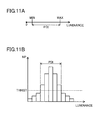
- FIG. 11A shows an example of a luminance distribution value PDI obtained by a luminance distribution calculator illustrated in FIG. 10 .
- FIG. 11B shows another example of the luminance distribution value PDI obtained by the luminance distribution calculator illustrated in FIG. 10 .
- FIG. 12 is a block diagram illustrating another example of the configuration of the image display device of the embodiment.
- FIG. 13A is a view illustrating an example of a region where edge strengths are to be obtained.
- FIG. 13B is a view illustrating another example of the region where edge strengths are to be obtained.
- FIG. 14 illustrates a pixel whose edge strength is to be obtained by a weighted edge strength calculator illustrated in FIG. 12 and its adjacent pixels.
- FIG. 15A is a histogram showing an example of distribution of edge strengths in the input image VI.
- FIG. 15B is a histogram showing another example of the distribution of edge strengths in the input image VI.
- FIG. 16A shows an example of threshold values of a comparator illustrated in FIG. 12 in the case of FIG. 15A .
- FIG. 16B shows an example of threshold values of the comparator illustrated in FIG. 12 in the case of FIG. 15B .
- FIG. 1 is a block diagram illustrating an example of a configuration of an image display device according to an embodiment of the present disclosure.
- the image display device illustrated in FIG. 1 includes an image processor 100 and a display device 62 .
- the image processor 100 includes an edge strength calculator 12 , a resolution determiner 20 , and a resolution enhancement processor 40 .
- the edge strength calculator 12 and the resolution determiner 20 serve as a resolution determination device.
- the resolution determiner 20 includes counters 22 A, 22 B, . . . , a selector 24 , a filter 26 , and a correction factor generator 28 .
- the resolution enhancement processor 40 includes a high-frequency component extractor 42 , a multiplier 44 , an adder 46 , a feature extractor 48 , and a limiter 52 .
- An input image VI is an HD image (e.g., 1080 p: a progressive image with 1080 effective scanning lines).
- the input image VI can be originally an HD image or can be an HD image upconverted from an original SD image (e.g., 480 p).
- upconverting/upconverted refers to conversion of an image with a relatively low resolution (e.g., an SD image) to an image with a larger number of pixels (e.g., an HD image).
- FIG. 2 illustrates an example of arrangement of pixels in the input image VI.
- the edge strength calculator 12 obtains an edge strength based on the luminance difference between a pixel and its adjacent pixel in the input image VI, and outputs the obtained edge strength to the counters 22 A, 22 B, . . . .
- the edge strength calculator 12 obtains, as an edge strength EG, an absolute value (i.e.,
- the edge strength calculator 12 obtains edge strengths EG for a plurality of pixels included in the input image VI, i.e., all the pixels in one frame of the input image VI, for example, and sequentially outputs the obtained edge strengths EG.
- the resolution determiner 20 determines whether or not the input image VI is an image upconverted from an image having a predetermined resolution or less based on distribution of the edge strengths EG (i.e., a relationship between each edge strength and the number of pixels associated with the edge strength), and outputs the determination result.
- the following description is directed to an example in which the resolution determiner 20 determines whether or not the input image VI is an image upconverted from an image with a resolution less than or equal to that of an SD image.
- FIG. 3 is a graph showing an example of distribution of edge strengths in the input image VI.
- the distribution of edge strengths EG differs between an image (HD) that is originally an HD image and an image (SD) upconverted from an original SD image.
- HD image
- SD image
- the image that is originally an HD image has a larger number NP of pixels associated with this range than the image upconverted from an original SD image.
- the counter 22 A counts the number of pixels whose edge strengths EG are within a predetermined range, and outputs the obtained count CTA to the selector 24 .
- each of the other counters 22 B, . . . counts the number of pixels whose edge strengths EG are within a predetermined range for each counter, and outputs the obtained count, e.g., a count CTB, to the selector 24 .
- the counter 22 A counts the number of pixels whose edge strengths EG are within the range of 11-20
- the counter 22 B counts the number of pixels whose edge strengths EG are within the range of 21-30.
- the resolution determiner 20 may include a larger number of counters each configured to count the number of pixels whose edge strengths EG are within a range corresponding to larger strengths EG.
- a range of edge strengths EG of pixels to be counted by each counter can be set in consideration of a possible range of the values of pixels.
- the resolution determiner 20 may include eight counters respectively counting the numbers of pixels associated with the eight ranges.
- FIG. 4 is a histogram corresponding to the graph of FIG. 3 .
- the number NP of pixels is represented for each section of edge strengths EG with respect to HD in FIG. 3 , for example.
- the numbers NP of pixels are represented in such a manner that the number of pixels (the count CTA) whose edge strengths EG are in the range of 11-20, the number of pixels (the count CTB) whose edge strengths EG are in the range of 21-30, and the number of pixels (the count CTC) whose edge strengths EG are in the range of 31-40, for example, are arranged in this order from the left of the graph.
- the selector 24 selects one of the counts output from the counters 22 A, 22 B, . . . based on a parameter PS input from the outside of the resolution determiner 20 , and outputs the selected count as a count CT to the filter 26 .
- the parameter PS is constant and the selector 24 selects the counter 22 A, for simplicity.
- the filter 26 smoothes the count selected by selector 24 along the time axis, and outputs the smoothed count FT to the correction factor generator 28 .
- the filter 26 is, for example, an infinite impulse response (IIR) filter, but may be another type of a filter for smoothing the input value along the time axis. The same holds for other filters, which will be described below.
- IIR infinite impulse response
- FIG. 5A is a graph showing an example of a relationship between the input value FT and an output value CF 1 in the correction factor generator 28 illustrated in FIG. 1 .
- the correction factor generator 28 generates a correction factor CF 1 based on the count FT, and outputs the correction factor CF 1 as a determination result to the multiplier 44 .
- the correction factor CF 1 is larger than 1 (one)
- the input image VI is determined to be an image upconverted from an image with a resolution less than or equal to that of an SD image.
- the correction factor CF 1 is less than or equal to 1 (one)
- the input image VI is determined to be an image generated from an image with a resolution higher than that of an SD image.
- FIG. 5B is a graph showing another example of the relationship between the input value FT and the output value CF 1 .
- the correction factor generator 28 may have a relationship shown in FIG. 5B , instead of that shown in FIG. 5A .
- the resolution enhancement processor 40 increases the resolution of the input image VI based on the correction factor CF 1 , and outputs the obtained image VP to the display device 62 .
- the resolution enhancement is, for example, an edge enhancement that is performed in the following manner.
- FIG. 6A shows an example of luminance at an edge of the input image VI.
- the abscissa represents the location of a pixel, and the ordinate represents the luminance.
- FIG. 6B shows luminance of an output of the high-frequency component extractor 42 illustrated in FIG. 1 in correspondence with FIG. 6A .
- FIG. 6C shows luminance of an output of the adder 46 illustrated in FIG. 1 in correspondence with FIG. 6A .
- FIG. 6D shows luminance of an output of the limiter 52 illustrated in FIG. 1 in correspondence with FIG. 6A .
- the high-frequency component extractor 42 extracts a high-frequency component from the input image VI, and outputs the extracted high-frequency component.
- the high-frequency component extractor 42 outputs—Y N ⁇ 1 +2Y N ⁇ Y N+1 with respect to a pixel with a luminance Y N , for example.
- the output of the high-frequency component extractor 42 has a luminance as shown in FIG. 6B .
- the multiplier 44 multiplies the output of the high-frequency component extractor 42 by the correction factor CF 1 , and outputs the product to the adder 46 .
- the adder 46 adds the output of the multiplier 44 to the input image VI, and outputs the result.
- the output of the adder 46 has a luminance as shown in FIG. 6C .
- the feature extractor 48 obtains features of a pixel with a luminance Y N , and outputs the features.
- the feature extractor 48 obtains a highest luminance LMAX and a minimum luminance LMIN as the features from the pixel with the luminance Y N and its adjacent eight pixels.
- the limiter 52 limits the luminance of an image obtained through the resolution enhancement described above to a range obtained based on the input image VI. Specifically, the limiter 52 limits a portion of the output of the adder 46 exceeding the luminance LMAX to a luminance LMAX, limits a portion of the output of the adder 46 below the luminance LMIN to a luminance LMIN, and outputs the resultant luminances LMAX and LMIN.
- the image VP subjected to the resolution enhancement and output from the limiter 52 is shown in FIG. 6D .
- the display device 62 includes a display panel, for example, and displays the image VP with an increased resolution.
- the resolution enhancement is not limited to an edge enhancement.
- the input image VI may be subjected to pattern detection and then replaced by an appropriate image in accordance with the result of the pattern detection. If the input image VI is determined to be an image upconverted from an image with a resolution less than or equal to that of an SD image (e.g., if the correction factor CF 1 is larger than 1 (one)), the resolution enhancement processor 40 may generate an image with a larger number of quantization levels than those of the input image VI, and outputs the generated image.
- the parameter PS is constant. Alternatively, the parameter PS may be changed as necessary.
- the parameter PS indicates the type of a device that has output the input image VI, for example. If the parameter PS indicates an optical disk recorder, it is known that the original image may have a low resolution. Thus, to perform determination using the number of pixels whose edge strengths EG are relatively low, the selector 24 selects the counter 22 A. If the parameter PS indicates a tuner that receives a broadcast signal, the original image is likely to be an image with a high resolution. Thus, to perform determination using the number of pixels whose edge strengths EG are relatively high, the selector 24 selects the counter 22 B.
- FIG. 7 is a block diagram illustrating another example of the configuration of the image display device of the embodiment.
- the image display device illustrated in FIG. 7 includes an image processor 200 and a display device 62 .
- the image processor 200 includes an edge strength calculator 12 , a resolution determiner 220 , and a resolution enhancement processor 240 .
- the edge strength calculator 12 and the resolution determiner 220 serve as a resolution determination device.
- FIG. 8 schematically shows a process in the resolution determiner 220 illustrated in FIG. 7 .
- the resolution determiner 220 includes counters 22 A, 22 B, . . . , a filter 226 , a comparator 232 , a sum calculator 234 , and a distribution shape determiner 236 .
- the resolution enhancement processor 240 is the same as the resolution enhancement processor 40 illustrated in FIG. 1 except for additionally including a selector 254 .
- the edge strength calculator 12 and the counters 22 A, 22 B, . . . are the same as those in the image display device illustrated in FIG. 1 , and thus description thereof is not repeated.
- the filter 226 smoothes a count CTA along the time axis, and outputs the smoothed count FA to the comparator 232 .
- the filter 226 smoothes a count CTB along the time axis, and outputs the smoothed count FB to the comparator 232 . The same holds for counts of the other counters.
- the comparator 232 compares the count FA with a threshold value THFA associated with the count FA. For example, if the count FA is larger than the threshold value THFA, the comparator 232 outputs 1 (one), and otherwise outputs 0 (zero), as a comparison result value CA representing a comparison result, to the sum calculator 234 . Similarly, the comparator 232 compares the count FB with a threshold value THFB associated with the count FB. If the count FB is larger than the threshold value THFB, the comparator 232 outputs 1 (one), and otherwise outputs 0 (zero), as a comparison result value CB representing a comparison result, to the sum calculator 234 .
- the comparator 232 also compares the other counts, e.g., the count FC, with the associated threshold values, e.g., a threshold value THFC, and outputs comparison result values CC, CD, CE, CF, CG, and CH, for example, representing comparison results.
- the other counts e.g., the count FC
- the associated threshold values e.g., a threshold value THFC
- the sum calculator 234 obtains the sum CS of the comparison result values CA, CB, . . . , and outputs the sum CS to the distribution shape determiner 236 .
- the sum CS is 2.
- the distribution shape determiner 236 compares the sum CS and a predetermined threshold value THCS. For example, if the sum CS is larger than the threshold value THCS, the distribution shape determiner 236 outputs 1 (one), and otherwise outputs 0 (zero), as a determination result DD. If the determination result DD is 0 (zero), the input image VI is determined to be an image upconverted from an image with a resolution less than or equal to that of an SD image. If the determination result DD is 1 (one), the input image VI is determined to be an image generated from an image with a resolution higher than that of an SD image.
- the selector 254 selects an input parameter PR 1 or PR 2 based on the determination result DD, and outputs the selected parameter PR 1 or PR 2 as a correction factor CF 2 .
- the parameters PR 1 and PR 2 are 1.0 and 1.5, respectively. If the determination result DD is 0 (zero), the selector 254 selects the parameter PR 2 . If the determination result DD is 1 (one), the selector 254 selects the parameter PR 1 .
- the other components of the resolution enhancement processor 240 except the selector 254 are the same as those of the resolution enhancement processor 40 illustrated in FIG. 1 except that the multiplier 44 multiplies the output of the high-frequency component extractor 42 by the correction factor CF 2 . Thus, description of these components is not repeated.
- the input image VI is an image upconverted from an image with a resolution less than or equal to that of an SD image.
- the range of the luminance value to be counted by, for example, the counter 22 A, the counter selected by the selector, the threshold value of the comparator 232 , and the threshold value of the distribution shape determiner 236 are changed to appropriate values.
- the input image VI is an image converted from an image with a predetermined resolution or less based on one frame of an image.
- the resolution of the input image VI can be enhanced based on this determination result, thereby enabling processing appropriate for the image and, accordingly, displaying a high-quality image. Since determination can be performed based on one frame of an image, the circuit scale can be reduced and a determination result can be quickly obtained.
- FIG. 9 illustrates a pixel whose edge strength is to be obtained by the edge strength calculator 12 illustrated in FIG. 1 or 7 and its adjacent (surrounding) pixels.
- the edge strength calculator 12 obtains the absolute value of the luminance difference between a pixel A and a pixel F in FIG. 9 as the edge strength EG.
- an edge strength may be obtained based on the luminance difference between the pixel A and another pixel adjacent to the pixel A.
- the edge strength calculator 12 may obtain an edge strength EG between the pixel A and a pixel E, or an edge strength EG between the pixel A and a pixel C or between the pixel A and a pixel H, which are disposed vertically in FIG. 9 .
- the edge strength calculator 12 may also obtain an edge strength EG between the pixel A and a pixel B, between the pixel A and a pixel D, between the pixel A and a pixel G, or between the pixel A and a pixel I, which are disposed in a slanting direction.
- the edge strength calculator 12 may calculate the absolute value of the luminance difference between the pixel A and each of the adjacent pixels B-I, and obtains the maximum value among the calculated absolute values as an edge strength EG.
- FIG. 10 is a block diagram illustrating another example of the configuration of the image display device of the embodiment.
- the image display device illustrated in FIG. 10 includes an image processor 300 and a display device 62 .
- the image processor 300 includes an edge strength calculator 12 , a resolution determiner 320 , a resolution enhancement processor 40 , and a luminance feature calculator 70 .
- the luminance feature calculator 70 includes a luminance distribution calculator 72 and a luminance variation calculator 74 .
- the resolution determiner 320 has the same configuration as that of the resolution determiner 20 illustrated in FIG. 1 except for including a filter 326 instead of the filter 26 .
- the edge strength calculator 12 , the resolution determiner 320 , and the luminance feature calculator 70 serve as a resolution determination device.
- the luminance feature calculator 70 obtains features of the luminance of a frame of an input image VI.
- the features of the luminance include a luminance distribution value PDI and a luminance variation amount PCH.
- the resolution determiner 320 performs determination based on not only distribution of edge strengths but also the luminance.
- the luminance feature calculator 70 may include only one of the luminance distribution calculator 72 or the luminance variation calculator 74 .
- FIG. 11A shows an example of a luminance distribution value PDI obtained by the luminance distribution calculator 72 illustrated in FIG. 10 .
- the luminance distribution calculator 72 obtains a luminance distribution value PDI corresponding to the width of luminance distribution of pixels in the frame of the input image VI.
- FIG. 11B shows another example of the luminance distribution value PDI obtained by the luminance distribution calculator 72 illustrated in FIG. 10 .
- the luminance distribution calculator 72 may obtain the width of a range where the luminances of pixels in the frame are concentrated, as a luminance distribution value PDI.
- the luminance distribution calculator 72 may, for example, include counters associated with sections in the histogram shown in FIG. 11B such that each of the counters counts the number of pixels, in one frame of the input image VI, whose luminances fall within the associated section.
- the number of counters is 16, and the width of a section associated with each of the counters is 1/16 of an expected maximum value of the luminances.
- the luminance distribution calculator 72 obtains, as the luminance distribution value PDI, the number of counters whose count numbers are greater than or equal to a predetermined threshold value THHIST, and outputs the luminance distribution value PDI to the selector 24 .
- the selector 24 receives the luminance distribution value PDI as a parameter PS, selects, based on the luminance distribution value PDI, one of counts CTA, CTB, . . . output from counters 22 A, 22 B, . . . , and outputs the selected count as a count CT to the filter 326 . For example, if the luminance distribution value PDI is less than a threshold value THDI, the selector 24 selects the count CTA, whereas if the luminance distribution value PDI is greater than or equal to the threshold value THDI, the selector 24 selects the count CTB.
- THDI threshold value
- the filter 326 smoothes the count CT along the time axis. If the luminance variation amount PCH is less than a predetermined threshold value THCH, the filter 326 outputs the smoothed count FT to the correction factor generator 28 . If the luminance variation amount PCH is greater than or equal to the predetermined threshold value THCH, the filter 326 does not smooth the count CT and outputs the count CT to the correction factor generator 28 . In this case, the current count CT is output from the filter 326 without change.
- a correction factor CF 1 (the determination result) is output from the correction factor generator 28 at a higher response speed.
- FIG. 12 is a block diagram illustrating another example of the configuration of the image display device of the embodiment.
- the image display device illustrated in FIG. 12 includes an image processor 400 and a display device 62 .
- the image processor 400 includes a weighted edge strength calculator 412 , a region determiner 414 , a resolution determiner 420 , a resolution enhancement processor 440 , and a luminance feature calculator 70 .
- the weighted edge strength calculator 412 , the region determiner 414 , the resolution determiner 420 , and the luminance feature calculator 70 serve as a resolution determination device.
- the resolution determiner 420 includes counters 22 A, 22 B, . . . , a selector 424 , filters 426 and 438 , a comparator 432 , a weighted sum calculator 434 , and a distribution shape determiner 436 .
- the resolution enhancement processor 440 is the same as the resolution enhancement processor 40 illustrated in FIG. 1 except for additionally including a correction factor calculator 456 .
- the counters 22 A, 22 B, . . . are the same as those in the image display device illustrated in FIG. 1 , and thus description thereof is not repeated.
- FIG. 13A is a view illustrating an example of a region where edge strengths are to be obtained.
- FIG. 13B is a view illustrating another example of the region where edge strengths are to be obtained.
- the region determiner 414 outputs a region determination result RD indicating that the region used for determination is a region where edge strengths are to be obtained basically with respect to the entire input image VI (e.g. 1920 ⁇ 1080 pixels).
- the region determiner 414 performs the following operation.
- the region determiner 414 determines whether or not a pixel in the input image VI is a pixel in the region WA 1 , and outputs the region determination result RD to the weighted edge strength calculator 412 .
- the region determiner 414 outputs 1 (one) if the pixel in the input image VI is a pixel in the region WA 1 , and otherwise outputs 0 (zero), as the region determination result RD.
- regions WB 1 and WB 2 as illustrated in FIG. 13B are specified, the region determiner 414 determines whether or not a pixel in the input image VI is a pixel in one of the regions WB 1 or WB 2 .
- FIG. 14 illustrates a pixel whose edge strength is to be obtained by the weighted edge strength calculator 412 illustrated in FIG. 12 and its adjacent pixels.
- Pixels A, B, C, D, E, F, G, H, and I are respectively associated with coefficients KA, KB, KC, KD, KE, KF, KG, KH, and KI.
- the coefficients KA, . . . , and KI are associated with locations relative to the pixel A whose edge strength is to be obtained.
- the weighted edge strength calculator 412 obtains an edge strength EG based on the luminance of a pixel in the input image VI and the luminance of its adjacent pixel, and outputs the obtained edge strength EG to the counters 22 A, 22 B, . . . based on the region determination result RD of the region determiner 414 .
- the edge strength calculator 412 assigns weights to the values of the pixel A and its adjacent pixels B-I, and adds these weighted values together.
- the pixels A, B, C, D, E, F, G, H, and I respectively have luminance values YA, YB, YC, YD, YE, YF, YG, YH, and YI
- the region determiner 414 performs determination and the edge strength calculator 412 uses the region determination result RD, influences of portions to be removed, e.g., side panels as margins at the left and right side of an image, a margin in a letterbox format, and a boundary formed when compositing images, can be removed from a target of resolution determination.
- the selector 424 selects a predetermined number of counts from counts CTA, CTB, . . . output from the counters 22 A, 22 B, . . . based on the luminance distribution value PDI, and outputs the selected values as counts SA, SB, . . . to the filter 426 .
- selector 424 selects eight counts CTA, CTB, . . . if the luminance distribution value PDI is less than the threshold value THDI, and selects eight counts CTB, CTC, . . . if the luminance distribution value PDI is greater than or equal to the threshold value THDI.
- the selector 424 may select the counts from all the counters 22 A, 22 B, . . . .
- the filter 426 smoothes the input counts SA, SB, . . . along the time axis. If the luminance variation amount PCH is less than the predetermined threshold value THCH, the filter 426 outputs the smoothed counts FA,FB, . . . to the comparator 432 . If the luminance variation amount PCH is greater than or equal to the predetermined threshold value THCH, the filter 426 does not smooth the input counts SA, SB, . . . , and outputs the counts SA, SB, . . . to the comparator 432 . In this case, the current count is output from the filter 426 without change.
- the comparator 432 compares the count FA with the associated threshold value THFA, outputs 1 (one) if the count FA is greater than the threshold value THFA, and otherwise outputs 0 (zero), as a comparison result value CA representing a comparison result, to the sum calculator 434 .
- the comparator 432 compares the count FB with the associated threshold value THFB, outputs 1 (one) if the count FB is greater than the threshold value THFB, and otherwise outputs 0 (zero), as a comparison result value CB representing a comparison result, to the sum calculator 434 .
- the comparator 432 also compares the other counts with the associated threshold values, and outputs comparison result values representing comparison results.
- the comparator 432 controls the threshold values THFA, THFB, THFC, . . . based on the luminance distribution value PDI.
- FIG. 15A is a histogram showing an example of distribution of edge strengths in the input image VI.
- FIG. 15B is a histogram showing another example of the distribution of edge strengths in the input image VI.
- FIG. 15A shows a case where the input image VI is relatively dark and the range of luminance distribution is narrow (i.e., the luminance distribution value PDI is small).
- FIG. 15B shows a case where the input image VI is relatively bright and the range of luminance distribution is wide (i.e., the luminance distribution value PDI is large).
- FIG. 16A shows an example of threshold values of the comparator 432 illustrated in FIG. 12 in the case of FIG. 15A .
- FIG. 16B shows an example of threshold values of the comparator 432 illustrated in FIG. 12 in the case of FIG. 15B .
- the comparator 432 increases threshold values associated with relatively low edge strengths and reduces threshold values associated with relatively high edge strengths, based on the luminance distribution value PDI (see FIG. 16A ).
- the comparator 432 reduces threshold values associated with relatively low edge strengths and increases threshold values associated with relatively high edge strengths, based on the luminance distribution value PDI (see FIG. 16B ). In this manner, the threshold values are controlled based on the luminance distribution value PDI.
- the comparator 432 can perform stable comparison independent of variations of luminance.
- the sum calculator 434 assigns weights to the comparison result values CA, CB, . . . , then adds these weighted values together, and outputs the obtained sum to the distribution shape determiner 436 .
- the sum calculator 434 individually multiplies the values CA, CB, . . . by their associated coefficients, and obtains the sum CS of the products.
- the sum calculator 434 multiples a comparison result associated with a higher edge strength by a larger coefficient, so that this comparison result has priority to other comparison results.
- the sum calculator 434 may set the coefficients associated with all the values CA, CB, . . . at 1 (one).
- the distribution shape determiner 436 compares the sum CS obtained by the sum calculator 434 with the predetermined threshold value THCS. If the sum CS is greater than the predetermined threshold value THCS, the distribution shape determiner 436 outputs 1 (one), and otherwise outputs 0 (zero), as a determination result DD. In the same manner as that illustrated in FIG.
- the input image VI is determined to be an image upconverted from an image with a resolution less than or equal to that of an SD image, whereas if the determination result DD is 1 (one), the input image VI is determined to be an image based on an image with a resolution higher than that of an SD image.
- the luminance distribution value PDI is less than the predetermined threshold value THJU, the distribution shape determiner 436 does not perform determination, and outputs the previously obtained determination result DD.
- the threshold value THJU is set at, for example, 8.
- the filter 438 smoothes the determination result DD output from the distribution shape determiner 436 along the time axis. If the luminance variation amount PCH is less than a predetermined threshold value THCH 2 , the filter 438 outputs the smoothed determination result DDF to the correction factor calculator 456 . If the luminance variation amount PCH is greater than or equal to the predetermined threshold value THCH 2 , the filter 438 does not smooth the input determination result DDF, and outputs the input determination result DDF to the correction factor calculator 456 . In this case, the current determination result DDF is output from the filter 438 without change.
- each functional block can be formed on a semiconductor substrate as a part of an integrated circuit (IC).
- an IC includes a large-scale integrated (LSI) circuit, an application-specific integrated circuit (ASIC), a gate array, a field programmable gate array (FPGA), etc.
- LSI large-scale integrated
- ASIC application-specific integrated circuit
- FPGA field programmable gate array
- part or all of each of the functional blocks can be implemented as software.
- such a functional block can be implemented as a program that is executed on a processor.
- each functional block described in this embodiment may be implemented as hardware, software, or a combination of hardware and software.
- the present disclosure is useful for resolution determination devices, image processors, and image display devices, for example.
Landscapes
- Engineering & Computer Science (AREA)
- Signal Processing (AREA)
- Multimedia (AREA)
- Physics & Mathematics (AREA)
- General Physics & Mathematics (AREA)
- Computer Vision & Pattern Recognition (AREA)
- Theoretical Computer Science (AREA)
- General Health & Medical Sciences (AREA)
- Quality & Reliability (AREA)
- Health & Medical Sciences (AREA)
- Biomedical Technology (AREA)
- Probability & Statistics with Applications (AREA)
- Picture Signal Circuits (AREA)
- Image Processing (AREA)
- Image Analysis (AREA)
- Testing, Inspecting, Measuring Of Stereoscopic Televisions And Televisions (AREA)
- Television Systems (AREA)
- Controls And Circuits For Display Device (AREA)
- Transforming Electric Information Into Light Information (AREA)
Abstract
Description
S2(n)=αS1(n)+(1−α)S2(n−1)
where α is a real-number coefficient, n is a natural number, and (n) indicates that the signal is associated with the n-th pixel. The
PDI=(highest luminance in one frame)−(lowest luminance in one frame)
and then outputs the obtained luminance distribution value PDI to a
PCH=|(average luminance of target frame)−(average luminance of previous frame)|
and outputs the obtained luminance variation amount PCH to the
EG=|KA·YA+KB·YB+KC·YC+KD·YD+KE·YE+KF·YF+KG·YG+KH·YH+KI·YI|
KA=2, KE=KF=−1,
then
KB=KC=KD=KG=KH=KI=0, EG=|−YE+2YA−YF|.
In this case, advantages as a bypass filter can be obtained. Thus, edge strengths of components with higher frequencies in the input image VI can be obtained with stability.
CF2=(1−β)·PR1+β·PR2
where β=DDF. With the
Claims (11)
Applications Claiming Priority (3)
| Application Number | Priority Date | Filing Date | Title |
|---|---|---|---|
| JP2010-139694 | 2010-06-18 | ||
| JP2010139694 | 2010-06-18 | ||
| PCT/JP2011/002245 WO2011158419A1 (en) | 2010-06-18 | 2011-04-15 | Resolution evaluation device, image processing apparatus, and image display apparatus |
Related Parent Applications (1)
| Application Number | Title | Priority Date | Filing Date |
|---|---|---|---|
| PCT/JP2011/002245 Continuation WO2011158419A1 (en) | 2010-06-18 | 2011-04-15 | Resolution evaluation device, image processing apparatus, and image display apparatus |
Publications (2)
| Publication Number | Publication Date |
|---|---|
| US20130107120A1 US20130107120A1 (en) | 2013-05-02 |
| US8830398B2 true US8830398B2 (en) | 2014-09-09 |
Family
ID=45347837
Family Applications (1)
| Application Number | Title | Priority Date | Filing Date |
|---|---|---|---|
| US13/718,604 Expired - Fee Related US8830398B2 (en) | 2010-06-18 | 2012-12-18 | Resolution determination device, image processor, and image display device |
Country Status (4)
| Country | Link |
|---|---|
| US (1) | US8830398B2 (en) |
| JP (1) | JPWO2011158419A1 (en) |
| CN (1) | CN102918831A (en) |
| WO (1) | WO2011158419A1 (en) |
Cited By (2)
| Publication number | Priority date | Publication date | Assignee | Title |
|---|---|---|---|---|
| US20130121555A1 (en) * | 2011-11-16 | 2013-05-16 | Herbert Bruder | Reconstruction of image data |
| US20150035847A1 (en) * | 2013-07-31 | 2015-02-05 | Lg Display Co., Ltd. | Apparatus for converting data and display apparatus using the same |
Families Citing this family (8)
| Publication number | Priority date | Publication date | Assignee | Title |
|---|---|---|---|---|
| JP5399578B2 (en) * | 2012-05-16 | 2014-01-29 | シャープ株式会社 | Image processing apparatus, moving image processing apparatus, video processing apparatus, image processing method, video processing method, television receiver, program, and recording medium |
| US9870375B2 (en) * | 2013-12-20 | 2018-01-16 | Nvidia Corporation | Image analysis of display content for dynamic adjustment of a continuous scan display |
| US9830871B2 (en) | 2014-01-03 | 2017-11-28 | Nvidia Corporation | DC balancing techniques for a variable refresh rate display |
| US9711099B2 (en) | 2014-02-26 | 2017-07-18 | Nvidia Corporation | Techniques for avoiding and remedying DC bias buildup on a flat panel variable refresh rate display |
| CN104917968B (en) * | 2015-06-01 | 2018-01-19 | 广东欧珀移动通信有限公司 | The method of adjustment and device of image boundary of taking pictures intensity |
| US9940898B2 (en) | 2016-02-25 | 2018-04-10 | Nvidia Corporation | Variable refresh rate video capture and playback |
| JP6967201B2 (en) * | 2017-09-26 | 2021-11-17 | 株式会社アイシン | Information processing equipment |
| CN112118439B (en) * | 2019-06-20 | 2024-01-23 | 瑞昱半导体股份有限公司 | Video quality detection method and image processing circuit |
Citations (11)
| Publication number | Priority date | Publication date | Assignee | Title |
|---|---|---|---|---|
| US5463697A (en) * | 1992-08-04 | 1995-10-31 | Aisin Seiki Kabushiki Kaisha | Apparatus for detecting an edge of an image |
| US6570616B1 (en) * | 1997-10-17 | 2003-05-27 | Nikon Corporation | Image processing method and device and recording medium in which image processing program is recorded |
| US20060274204A1 (en) | 2005-06-01 | 2006-12-07 | Hitachi, Ltd. | Picture display system for adjusting image quality of a picture signal having higher number of scanning lines |
| US20070268400A1 (en) | 2006-05-18 | 2007-11-22 | Sony Corporation | Image processing apparatus, image processing method, and program |
| US20090009660A1 (en) | 2007-07-05 | 2009-01-08 | Masahiro Kageyama | Video displaying apparatus, video signal processing apparatus and video signal processing method |
| JP2009015025A (en) | 2007-07-05 | 2009-01-22 | Hitachi Ltd | Image signal processing apparatus and image signal processing method |
| US20090028465A1 (en) * | 2007-07-24 | 2009-01-29 | Hao Pan | Image upscaling technique |
| US20090041349A1 (en) | 2007-08-07 | 2009-02-12 | Masaru Suzuki | Image determining device, image determining method, and program |
| US20100226579A1 (en) * | 2009-03-05 | 2010-09-09 | Samsung Electronics Co., Ltd. | Image processing method and apparatus for detecting an edge of an object within an image |
| US20110081094A1 (en) * | 2008-05-21 | 2011-04-07 | Koninklijke Philips Electronics N.V. | Image resolution enhancement |
| US20110085703A1 (en) * | 2003-07-18 | 2011-04-14 | Lockheed Martin Corporation | Method and apparatus for automatic object identification |
-
2011
- 2011-04-15 WO PCT/JP2011/002245 patent/WO2011158419A1/en not_active Ceased
- 2011-04-15 JP JP2012520250A patent/JPWO2011158419A1/en not_active Withdrawn
- 2011-04-15 CN CN2011800267962A patent/CN102918831A/en active Pending
-
2012
- 2012-12-18 US US13/718,604 patent/US8830398B2/en not_active Expired - Fee Related
Patent Citations (14)
| Publication number | Priority date | Publication date | Assignee | Title |
|---|---|---|---|---|
| US5463697A (en) * | 1992-08-04 | 1995-10-31 | Aisin Seiki Kabushiki Kaisha | Apparatus for detecting an edge of an image |
| US6570616B1 (en) * | 1997-10-17 | 2003-05-27 | Nikon Corporation | Image processing method and device and recording medium in which image processing program is recorded |
| US20110085703A1 (en) * | 2003-07-18 | 2011-04-14 | Lockheed Martin Corporation | Method and apparatus for automatic object identification |
| US20060274204A1 (en) | 2005-06-01 | 2006-12-07 | Hitachi, Ltd. | Picture display system for adjusting image quality of a picture signal having higher number of scanning lines |
| JP2006339934A (en) | 2005-06-01 | 2006-12-14 | Hitachi Ltd | Video display device |
| US20070268400A1 (en) | 2006-05-18 | 2007-11-22 | Sony Corporation | Image processing apparatus, image processing method, and program |
| JP4193871B2 (en) | 2006-05-18 | 2008-12-10 | ソニー株式会社 | Image processing apparatus, image processing method, and program |
| US20090009660A1 (en) | 2007-07-05 | 2009-01-08 | Masahiro Kageyama | Video displaying apparatus, video signal processing apparatus and video signal processing method |
| JP2009015025A (en) | 2007-07-05 | 2009-01-22 | Hitachi Ltd | Image signal processing apparatus and image signal processing method |
| US20090028465A1 (en) * | 2007-07-24 | 2009-01-29 | Hao Pan | Image upscaling technique |
| US20090041349A1 (en) | 2007-08-07 | 2009-02-12 | Masaru Suzuki | Image determining device, image determining method, and program |
| JP2009044341A (en) | 2007-08-07 | 2009-02-26 | Sony Corp | Image determination apparatus, image determination method, and program |
| US20110081094A1 (en) * | 2008-05-21 | 2011-04-07 | Koninklijke Philips Electronics N.V. | Image resolution enhancement |
| US20100226579A1 (en) * | 2009-03-05 | 2010-09-09 | Samsung Electronics Co., Ltd. | Image processing method and apparatus for detecting an edge of an object within an image |
Non-Patent Citations (1)
| Title |
|---|
| International Search Report mailed Jul. 26, 2011 issued in corresponding International Application No. PCT/JP2011/002245. |
Cited By (4)
| Publication number | Priority date | Publication date | Assignee | Title |
|---|---|---|---|---|
| US20130121555A1 (en) * | 2011-11-16 | 2013-05-16 | Herbert Bruder | Reconstruction of image data |
| US9147267B2 (en) * | 2011-11-16 | 2015-09-29 | Siemens Aktiengesellschaft | Reconstruction of image data |
| US20150035847A1 (en) * | 2013-07-31 | 2015-02-05 | Lg Display Co., Ltd. | Apparatus for converting data and display apparatus using the same |
| US9640103B2 (en) * | 2013-07-31 | 2017-05-02 | Lg Display Co., Ltd. | Apparatus for converting data and display apparatus using the same |
Also Published As
| Publication number | Publication date |
|---|---|
| WO2011158419A1 (en) | 2011-12-22 |
| CN102918831A (en) | 2013-02-06 |
| JPWO2011158419A1 (en) | 2013-08-19 |
| US20130107120A1 (en) | 2013-05-02 |
Similar Documents
| Publication | Publication Date | Title |
|---|---|---|
| US8830398B2 (en) | Resolution determination device, image processor, and image display device | |
| US7940333B2 (en) | Gradation control apparatus and gradation control method | |
| CN106846270B (en) | Image edge enhancement method and device | |
| US8305397B2 (en) | Edge adjustment method, image processing device and display apparatus | |
| US8339518B2 (en) | Video signal processing method and apparatus using histogram | |
| KR20020008179A (en) | System and method for improving the sharpness of a video image | |
| US8976298B2 (en) | Efficient 2D adaptive noise thresholding for video processing | |
| US20120008692A1 (en) | Image processing device and image processing method | |
| KR101634652B1 (en) | Method and apparatus for intensificating contrast in image | |
| TWI404408B (en) | Image processing apparatus and image processing method | |
| US20100272372A1 (en) | Image Processing Apparatus and Image Processing Method | |
| US9147231B2 (en) | Resolution determination device, image processing device, and image display apparatus | |
| TWI517097B (en) | Method, apparatus, and non-transitory computer readable medium for enhancing image contrast | |
| US7916950B2 (en) | Image processing method and apparatus thereof | |
| TWI390958B (en) | Video filter and video processor and processing method using thereof | |
| US8704951B1 (en) | Efficient 2D adaptive noise thresholding for video processing | |
| JP6008125B2 (en) | Noise reduction device and noise reduction method | |
| WO2011102046A1 (en) | Image processing system and display device | |
| JP5257291B2 (en) | Video signal processing apparatus, dot interference detection method and program | |
| KR100710356B1 (en) | How to adjust the histogram | |
| JP5193976B2 (en) | Video processing apparatus and video display apparatus | |
| JP4843367B2 (en) | Y / C separation circuit | |
| JP5111412B2 (en) | Image display apparatus and image processing method | |
| JPWO2011099201A1 (en) | Motion detection device, control program, and integrated circuit | |
| CN112351152A (en) | Image processing circuit and related image processing method |
Legal Events
| Date | Code | Title | Description |
|---|---|---|---|
| AS | Assignment |
Owner name: PANASONIC CORPORATION, JAPAN Free format text: ASSIGNMENT OF ASSIGNORS INTEREST;ASSIGNORS:INOUE, KOICHI;TOMIOKA, SHINICHI;KAGEYAMA, ATSUHISA;SIGNING DATES FROM 20121203 TO 20121205;REEL/FRAME:031956/0348 |
|
| STCF | Information on status: patent grant |
Free format text: PATENTED CASE |
|
| FEPP | Fee payment procedure |
Free format text: PAYOR NUMBER ASSIGNED (ORIGINAL EVENT CODE: ASPN); ENTITY STATUS OF PATENT OWNER: LARGE ENTITY |
|
| MAFP | Maintenance fee payment |
Free format text: PAYMENT OF MAINTENANCE FEE, 4TH YEAR, LARGE ENTITY (ORIGINAL EVENT CODE: M1551) Year of fee payment: 4 |
|
| FEPP | Fee payment procedure |
Free format text: MAINTENANCE FEE REMINDER MAILED (ORIGINAL EVENT CODE: REM.); ENTITY STATUS OF PATENT OWNER: LARGE ENTITY |
|
| LAPS | Lapse for failure to pay maintenance fees |
Free format text: PATENT EXPIRED FOR FAILURE TO PAY MAINTENANCE FEES (ORIGINAL EVENT CODE: EXP.); ENTITY STATUS OF PATENT OWNER: LARGE ENTITY |
|
| STCH | Information on status: patent discontinuation |
Free format text: PATENT EXPIRED DUE TO NONPAYMENT OF MAINTENANCE FEES UNDER 37 CFR 1.362 |
|
| FP | Lapsed due to failure to pay maintenance fee |
Effective date: 20220909 |