US8824947B2 - Fixing device and image forming apparatus including the same - Google Patents

Fixing device and image forming apparatus including the same Download PDF

Info

Publication number
US8824947B2
US8824947B2 US13/332,584 US201113332584A US8824947B2 US 8824947 B2 US8824947 B2 US 8824947B2 US 201113332584 A US201113332584 A US 201113332584A US 8824947 B2 US8824947 B2 US 8824947B2
Authority
US
United States
Prior art keywords
toner
recording sheet
fixing
fixing device
laser
Prior art date
Legal status (The legal status is an assumption and is not a legal conclusion. Google has not performed a legal analysis and makes no representation as to the accuracy of the status listed.)
Active, expires
Application number
US13/332,584
Other versions
US20120201584A1 (en
Inventor
Tomohiro Maeda
Current Assignee (The listed assignees may be inaccurate. Google has not performed a legal analysis and makes no representation or warranty as to the accuracy of the list.)
Sharp Corp
Original Assignee
Sharp Corp
Priority date (The priority date is an assumption and is not a legal conclusion. Google has not performed a legal analysis and makes no representation as to the accuracy of the date listed.)
Filing date
Publication date
Application filed by Sharp Corp filed Critical Sharp Corp
Assigned to SHARP KABUSHIKI KAISHA reassignment SHARP KABUSHIKI KAISHA ASSIGNMENT OF ASSIGNORS INTEREST (SEE DOCUMENT FOR DETAILS). Assignors: MAEDA, TOMOHIRO
Publication of US20120201584A1 publication Critical patent/US20120201584A1/en
Application granted granted Critical
Publication of US8824947B2 publication Critical patent/US8824947B2/en
Active legal-status Critical Current
Adjusted expiration legal-status Critical

Links

Images

Classifications

    • GPHYSICS
    • G03PHOTOGRAPHY; CINEMATOGRAPHY; ANALOGOUS TECHNIQUES USING WAVES OTHER THAN OPTICAL WAVES; ELECTROGRAPHY; HOLOGRAPHY
    • G03GELECTROGRAPHY; ELECTROPHOTOGRAPHY; MAGNETOGRAPHY
    • G03G15/00Apparatus for electrographic processes using a charge pattern
    • G03G15/20Apparatus for electrographic processes using a charge pattern for fixing, e.g. by using heat
    • G03G15/2003Apparatus for electrographic processes using a charge pattern for fixing, e.g. by using heat using heat
    • G03G15/2007Apparatus for electrographic processes using a charge pattern for fixing, e.g. by using heat using heat using radiant heat, e.g. infrared lamps, microwave heaters
    • G03G15/201Apparatus for electrographic processes using a charge pattern for fixing, e.g. by using heat using heat using radiant heat, e.g. infrared lamps, microwave heaters of high intensity and short duration, i.e. flash fusing

Definitions

  • the present invention relates to a fixing device used for an electrophotographic image forming apparatus such as a copier, a printer or a facsimile, and more specifically to a fixing device for fixing an unfixed image formed on a recording member by noncontact means such as laser beam irradiation means, and an image forming apparatus including the same.
  • An electrophotographic image forming apparatus for example, a copier, a printer, a facsimile or the like
  • a fixing device for fixing a toner image formed on a recording member (recording sheet, or the like) by heating and fusing.
  • a roller-pair system fixing device comprised of a fixing roller and a pressing roller is known.
  • the fixing roller is a roller member having an elastic layer formed on the surface of a hollow cored bar made of metal such as aluminum, and has a configuration in which a halogen lamp is arranged inside the cored bar as a heat source.
  • a temperature control device then performs on/off control of the halogen lamp based on a signal that is output from a temperature sensor provided on the surface of the fixing roller, thereby controlling temperature on the surface of the fixing roller.
  • the pressing roller is a roller member having a heat-resistant elastic layer such as silicone rubber provided on the cored bar as a coating layer.
  • a pressing roller is in press-contact with a peripheral face of the fixing roller, having a nip area that is formed with the fixing roller therebetween due to elastic deformation of the above-described elastic layer of the pressing roller.
  • a recording sheet on which an unfixed toner image is formed is held in the nip area between the fixing roller and the pressing roller, and both of these rollers are rotated, thereby conveying the above-described recording sheet, as well as fusing and fixing on the recording sheet the toner image on the recording sheet by heat of the peripheral face of the fixing roller.
  • the fixing roller and the pressing roller right after supplying power are at room temperature in the case of a power-off state of the device for a long period of time, thus needed to be increased to a predetermined temperature and required to have a warm-up period.
  • Patent Literature 2 As a method of effectively fixing only a toner without consuming wasted energy, a fixing device has been proposed for fixing a toner using laser power as described in the following Patent Literature 2.
  • Patent Literature 2 a plurality of lasers are used to directly heat a toner.
  • a plurality of lasers are used so that fixability which is insufficient only with one weak laser is improved.
  • the surface of the fixing roller is not needed to be maintained at a predetermined temperature, and wasted energy is thus not consumed. It is also described that it is possible to use an inexpensive laser by low output, thus making it possible to also simplify the whole of the device.
  • Patent Literature 1 in the case of a contact-fixing method for fixing a toner by heating and pressing including widely-used roller fixation, belt fixation and the like, for adhesion between the toner and a recording sheet, the toner which is fused by heating is subjected to pressure with a roller nip portion (contact portion of a roller which serves as an upper roller) so as to have promoted diffusion (adhesion force) to paper for adherence, thereby attaining favorable fixability.
  • a roller nip portion contact portion of a roller which serves as an upper roller
  • the present invention has been devised in view of the above-described problems, and an object thereof is to provide a fixing device for reforming a surface of a toner on a recording sheet to increase affinity of the toner that is heated and fused by a noncontact fixing portion to the recording sheet, thereby obtaining a favorable fixed image, and an image forming apparatus including the same.
  • the present invention provides a fixing device for fixing an unfixed toner image in noncontact while conveying a recording member on which the toner image is formed, including
  • a surface reforming portion for reforming a surface of the toner on the recording member so as to increase affinity to the recording member in heating and fusing
  • a noncontact fixing portion for heating and fusing in noncontact the toner whose surface is reformed.
  • the recording member is paper and the surface reforming portion increases affinity to the recording member by generating a polar group of hydrophilic property on the surface of the toner.
  • the noncontact fixing portion fixes a toner image by irradiation of light, and preferably uses a laser beam. Additionally, the noncontact fixing portion desirably uses a semiconductor laser. Note that, in this case, a laser array is configured such that a plurality of semiconductor laser elements are disposed in an array in a direction orthogonal to a conveyance direction of the recording member.
  • the present invention provides an image forming apparatus provided with the fixing device.
  • a surface of a toner formed on a recording member is subjected to surface reformation by means of, for example, plasma irradiation or the like so as to increase affinity to the recording member, thereby increasing adhesiveness to the recording member when a toner is heated and fused so that it is possible to secure favorable fixability.
  • a polar group of a hydrophilic property is generated on the surface of the toner so that it is possible to increase affinity to the recording member.
  • heating is performed by light irradiation so that there is no need for warm-up of a heating portion, and it is possible to heat and fuse instantly only at the time of desiring fixation to effectively perform fixation.
  • a laser since a laser has less light diffusion, a largest amount of light is able to be condensed by the combined use of a laser and a condensing lens so that it is possible to bring maximum light intensity (light output per unit area: W/mm 2 ), thus making it possible to effectively irradiate with light.
  • a semiconductor laser is used among lasers so that it is possible to reduce the cost because of lower cost of elements compared to use of a CO2 laser and a YAG laser.
  • semiconductor laser elements are disposed in a line in a sheet conveyance direction and a vertical direction so that it is not necessary to scan with a laser in the sheet conveyance direction and the vertical direction, thus enabling use in a most basic configuration and also fixation at high speed.
  • FIG. 1 is a schematic view showing an embodiment of a color image forming apparatus according to the present invention
  • FIG. 2 is a schematic view showing a fixing device that is used for the image forming apparatus
  • FIG. 3 is a schematic view showing a surface reforming device that is used for the fixing device.
  • FIG. 4 is a schematic view showing laser irradiation means that is used for the fixing device.
  • FIG. 1 shows an inner structure of a dry electrophotographic color image forming apparatus.
  • the image forming apparatus forms, for example, a multicolor or unicolor image on a predetermined recording member based on image data that is sent from each terminal device over a network, and the like.
  • the recording member for performing image formation is paper.
  • the above-described image forming apparatus is provided with a supply tray 20 , visible image formation units 50 ( 50 Y, 50 M, 50 C and 50 B), a recording sheet conveyance portion 30 and a fixing device 40 .
  • the above-described image forming apparatus has four visible image formation units 50 Y, 50 M, 50 C and 50 B that are arranged side by side, corresponding to each color of yellow (Y), magenta (M), cyan (C) and black (B).
  • the visible image formation unit 50 Y performs image formation with use of a toner of yellow (Y)
  • the visible image formation unit 50 M performs image formation with use of a toner of magenta (M)
  • the visible image formation unit 50 C performs image formation with use of a toner of cyan (C)
  • the visible image formation unit 50 B performs image formation with use of a toner of black (B).
  • a so-called tandem system is provided that four sets of the visible image formation unit 50 are disposed along a conveyance path of a recording sheet which connects the supply tray 20 of the recording sheet P and the fixing device 40 .
  • each of the visible image formation units 50 has a substantially same configuration. Namely, each of the visible image formation units 50 is provided with a photoreceptor drum 51 , a charger 52 , a laser beam irradiation portion 53 (here, referred to a laser beam irradiation portion for writing a latent image into a photoreceptor drum), a developing equipment 54 , a transfer roller 55 , and a cleaner unit 56 , and performs multi layer transfer with the toner in each color to the recording sheet P to be conveyed.
  • a photoreceptor drum 51 a charger 52 , a laser beam irradiation portion 53 (here, referred to a laser beam irradiation portion for writing a latent image into a photoreceptor drum), a developing equipment 54 , a transfer roller 55 , and a cleaner unit 56 , and performs multi layer transfer with the toner in each color to the recording sheet P to be conveyed.
  • a laser beam irradiation portion 53
  • the above-described photoreceptor drum 51 carries an image that is formed.
  • the above-described charger 52 uniformly charges the surface of the photoreceptor drum 51 to a predetermined potential.
  • the laser beam irradiation portion 53 exposes the surface of the photoreceptor drum 51 charged by the charger 52 corresponding to image data input to the image forming apparatus, and forms an electrostatic latent image on the surface of the photoreceptor drum 51 .
  • the above-described developing equipment 54 visualizes the electrostatic latent image formed on the surface of the photoreceptor drum 51 with the toner in each color.
  • the transfer roller 55 has bias with polarity opposite to that of the toner applied thereto, and transfers a toner image that is formed on the surface of the photoreceptor drum 51 to the recording sheet P conveyed by the recording sheet conveyance portion 30 described below.
  • the drum cleaner unit 56 removes and collects a toner remained on the surface of the photoreceptor drum after developing processing in the developing equipment 54 and transfer of an image formed on the photoreceptor drum 51 .
  • Transfer of a toner image to the recording sheet P as described above is repeated four times for four colors.
  • the recording sheet conveyance portion 30 includes a driving roller 31 , an idling roller 32 and a conveyor belt 33 , and conveys the recording sheet P so that a toner image that is formed with the visible image formation units 50 is transferred to the recording sheet P.
  • the driving roller 31 and the idling roller 32 are provided for stretching out the endless conveyor belt 33 , and the driving roller 31 rotates at a predetermined circumferential speed under control so as to rotate the endless conveyor belt 33 .
  • the conveyor belt 33 generates static electricity on an outer surface thereof, and conveys the above-described recording sheet P with electrostatic attraction.
  • the above-described recording sheet P is peeled off from the conveyor belt 33 at curvature of the driving roller 31 to be conveyed to the fixing device 40 .
  • the fixing device 40 applies appropriate heat to the recording sheet for fusing a toner to be fixed to the recording sheet so as to form a robust image.
  • FIG. 2 is a view in the case of viewing from the side of the laser fixing device 40 in a sheet conveyance direction.
  • the fixing device 40 includes a laser irradiation portion (noncontact fixing portion) 41 , a recording sheet conveyance device 100 for conveying the recording sheet P and a surface reforming device 108 .
  • the recording sheet conveyance device 100 is comprised of two tension rollers 101 and 102 , and an endless recording sheet conveyor belt 103 having heat resistance, in which the recording sheet P is conveyed on the belt 103 .
  • Each of the two tension rollers 101 and 102 has an unillustrated shaft core which is connected to an unillustrated bearing, and the tension roller 101 is connected to an unillustrated driving portion via an unillustrated gear.
  • the recording sheet conveyor belt 103 is comprised of materials in which a conductive member such as carbon is dispersed in a resin such as polycarbonate, vinylidene fluoride, polyamide-imide, or polymide, and configured so that voltage is applied by means of unillustrated bias applying means that is connected to an inner surface of the recording sheet conveyor belt 103 , whereby the recording sheet P is electrostatically attracted to the surface (outer peripheral face) of the recording sheet conveyor belt 103 .
  • a conductive member such as carbon is dispersed in a resin such as polycarbonate, vinylidene fluoride, polyamide-imide, or polymide
  • the recording sheet P is electrostatically attracted to the recording sheet conveyor belt 103 so that the recording sheet conveyor belt 103 adheres tightly to the recording sheet P, and it is possible to prevent the recording sheet P from floating as much as possible.
  • the surface of the recording sheet conveyor belt 103 intersects with a surface vertical to a light axis 110 as shown in FIG. 2 .
  • the surface reforming device 108 is installed on an upstream side in the sheet conveyance direction with respect to the laser irradiation portion 41 having a laser beam source, and reforms the surface of a toner T on a sheet having an unfixed image thereon.
  • treatment capable of reforming a surface of a toner may be available including atmospheric-pressure plasma treatment, low-pressure plasma treatment, corona discharge treatment and ultraviolet treatment and the like.
  • atmospheric-pressure plasma treatment device as such a surface reforming device.
  • the atmospheric-pressure plasma treatment device performs surface reformation by generating glow discharge in atmospheric pressure, which device is thus able to be simplified compared to that of vacuum plasma treatment, and as shown in FIG. 2 , it is possible to continuously irradiate to what is continuously conveyed such as a sheet in atmospheric pressure. Therefore, here, it is assumed that a plasma irradiation device is used as the surface reforming device 108 .
  • FIG. 3A is a vertical longitudinal sectional view of the device in the case of viewing from a direction orthogonal to the sheet conveyance direction.
  • FIG. 3B is a detailed view of a plasma irradiation nozzle 153 .
  • high voltage for example, 2 to 10 kV
  • high voltage for example, 2 to 10 kV
  • the two electrodes (1 cm to 20 cm as a distance) in a range of 10 ⁇ A to 50 mA
  • the air is flowed between the electrodes, so that oxygen or the like in the air generates a radical and radical oxygen attacks (reacts with a part with C-H binding in a resin)
  • a surface of a toner for example, a major component of the toner is a resin such as polyester and styrene acryl
  • a hydrophilic group such as an OH group and a carbonyl group.
  • a surface treatment device takes outside air into the device by means of a fan 154 ( FIG. 3A ) to deliver plasma to a surface of a toner.
  • a plasma generator in atmospheric pressure includes, for example, a plasma irradiation surface reforming device PS-601SW (manufactured by Wedge Co., Ltd.) and an atmospheric pressure plasma irradiation device disclosed in Japanese Patent Application Laid-open No. 2009-87697 and the like, and may have any configuration in which such a plasma irradiation device makes it possible to introduce a hydrophilic group onto a surface of a toner.
  • polyethylene (PE) is improved from 31 mN/m to 70 mN/m, and in the same manner, acryl is improved from 38 mN/m to 70 mN/m, and the like, as well as improving wettability for many other resins, and besides, it is also possible to improve wettability of a polyester resin and an acrylic resin which are major components of a toner by applying surface treatment as with these PE and acryl.
  • FIG. 4 is a view showing a configuration of the laser irradiation portion 41 .
  • FIG. 4A is a cross-sectional view of the laser irradiation portion 41 along a conveyance direction of the recording sheet P
  • FIG. 4B is a front view of the laser irradiation portion 41 in the case of viewing from the conveyance direction of the recording sheet P.
  • the laser irradiation portion 41 is a device for emitting a laser beam.
  • a plurality of semiconductor laser elements 213 are provided across a width direction of the recording sheet conveyor belt 103 for fixation.
  • the plurality of semiconductor laser elements 213 serving as a semiconductor laser element array are arrayed in a line in a direction orthogonal to the recording sheet conveyance direction having equal space from the surface of the recording sheet conveyor belt 103 , respectively. That is, the semiconductor laser element array is disposed parallel to the surface of the recording sheet conveyor belt 103 .
  • a laser beam that is emitted from the semiconductor laser element 213 has a cross-section in an approximately true circle shape vertical to an emission direction that is a direction to which the laser beam moves.
  • Each of the semiconductor laser elements 213 is provided so that each emission direction of a laser beam to be emitted is all the same, so as to be a direction vertical to a direction in which the semiconductor laser elements 213 are arrayed.
  • the semiconductor laser element 213 one having a wavelength of a laser beam to be emitted that is 400 nm to 1000 nm is arbitrarily selectable.
  • Each semiconductor laser element 213 is provided on each silicon substrate 212 that is formed of silicon.
  • an unillustrated control circuit and a light receiving element 214 are monolithically formed.
  • the light receiving element 214 is photodiode for a monitor.
  • the control circuit controls voltage that is applied to the semiconductor laser element 213 based on a signal that is input from the light receiving element 214 so that output of a laser beam is changed and kept constant.
  • control circuit and the semiconductor laser element 213 are electrically connected to each other via an unillustrated electrode and a bonding wire.
  • a temperature sensor 215 such as a thermistor is provided in order to measure temperature of each semiconductor laser element 213 .
  • the control circuit controls voltage that is applied to the semiconductor laser element 213 based on temperature data that is detected by the temperature sensor 215 .
  • the silicon substrate 212 is provided on a ceramic substrate 211 on the surface opposite to the surface on which the semiconductor laser element 213 is provided.
  • a not-shown electrode on the ceramic substrate 211 and a not-shown electrode on the silicon substrate 212 are electrically connected to each other by wire bonding or the like.
  • a heat sink 218 is provided on the surface opposite to the surface on which the silicon substrate 212 is provided.
  • a lens array 216 is provided on a downstream side in an irradiation direction of the semiconductor laser element 213 .
  • the lens array 216 includes the same number of a convex lens 217 a as a total number of semiconductor laser elements 213 , and a lens holder 217 b for holding the convex lens 217 a.
  • the lens array 216 is configured so that a laser beam emitted from each of the semiconductor laser elements 213 enters each of the convex lenses 217 a , respectively.
  • the laser irradiation section 41 in the present embodiment is a semiconductor laser element array in which a plurality of semiconductor laser elements 213 are arrayed in a line in a direction vertical to the recording sheet conveyance direction (width direction of the recording sheet conveyor belt 103 for fixation) having equal space from the surface of the recording sheet conveyor belt 103 for fixation, respectively.
  • the semiconductor laser element array is disposed parallel to the surface of the recording sheet conveyor belt 103 for fixation.
  • the laser irradiation portion 41 is configured to be the semiconductor laser element array so that it is not needed to scan with a laser beam in the width direction of the recording sheet P, thus making it possible to fix at high speed with a simple device configuration.
  • high output in a configuration in which a plurality of semiconductor laser elements 213 are provided makes an area of a heat radiation portion in the laser irradiation portion 41 larger. It is possible to improve a heat transfer efficiency to the heat sink 218 which is the heat radiation portion.
  • the recording sheet P has an unfixed toner image that is formed thereon with the visible image formation unit 50 , and is conveyed to the fixing device 40 .
  • the surface reforming device 108 of the fixing device 40 performs surface reformation for the surface of the toner T on the recording sheet P by, for example, plasma irradiation or the like, thereby generating a polar group of a hydrophilic property on the surface of the toner.
  • the recording sheet P is conveyed to the laser irradiation portion 41 by the recording sheet conveyance device 100 to be irradiated with a laser, in which the toner T is fused to be fixed to the recording sheet.
  • the toner T on the recording sheet P is subjected to surface reforming treatment, thus having increased affinity (adhesion force) with the recording sheet P, so that it is possible to secure favorable fixability without pressing.
  • heating is performed by light irradiation so that there is no need for warm-up of a heating portion, and it is possible to heat and fuse instantly only at the time of desired fixation to effectively perform fixation.
  • noncontact fixation by means of a laser is performed in the embodiment, however, noncontact fixation may be performed by means of light irradiation with a flash lamp, an LED and the like, oven heating and the like.
  • a semiconductor laser is used among lasers so that it is possible to reduce the cost because of lower cost of elements compared to use of a CO2 laser (carbon dioxide laser) and a YAG laser (solid-state laser using yttrium/aluminum/garnet).
  • CO2 laser carbon dioxide laser
  • YAG laser solid-state laser using yttrium/aluminum/garnet

Abstract

A recording sheet has an unfixed toner image that is formed thereon, and is conveyed to a fixing device. A surface reforming device of the fixing device performs surface reformation for the surface of the toner on the recording sheet by, for example, plasma irradiation or the like, thereby generating a polar group of a hydrophilic property on the surface of the toner. Next, the recording sheet is conveyed to a laser irradiation portion by a recording sheet conveyance device to be irradiated with a laser, in which the toner is fused to be fixed to the recording sheet. The toner on the recording sheet is subjected to surface reforming treatment, thus having increased affinity (adhesion force) with the recording sheet, so that it is possible to secure favorable fixability without pressing.

Description

This Nonprovisional application claims priority under 35 U.S.C. §119(a) on Patent Application No. 2011-22008 filed in Japan on 3 Feb. 2011, the entire contents of which are hereby incorporated by reference.
BACKGROUND OF THE INVENTION
1. Field of the Invention
The present invention relates to a fixing device used for an electrophotographic image forming apparatus such as a copier, a printer or a facsimile, and more specifically to a fixing device for fixing an unfixed image formed on a recording member by noncontact means such as laser beam irradiation means, and an image forming apparatus including the same.
2. Description of the Prior Art
An electrophotographic image forming apparatus (for example, a copier, a printer, a facsimile or the like) is provided with a fixing device for fixing a toner image formed on a recording member (recording sheet, or the like) by heating and fusing. As an example of such a fixing device, as shown in the following Patent Literature 1, a roller-pair system fixing device comprised of a fixing roller and a pressing roller is known.
The fixing roller is a roller member having an elastic layer formed on the surface of a hollow cored bar made of metal such as aluminum, and has a configuration in which a halogen lamp is arranged inside the cored bar as a heat source. A temperature control device then performs on/off control of the halogen lamp based on a signal that is output from a temperature sensor provided on the surface of the fixing roller, thereby controlling temperature on the surface of the fixing roller.
The pressing roller is a roller member having a heat-resistant elastic layer such as silicone rubber provided on the cored bar as a coating layer. Such a pressing roller is in press-contact with a peripheral face of the fixing roller, having a nip area that is formed with the fixing roller therebetween due to elastic deformation of the above-described elastic layer of the pressing roller.
With the above-described configuration, in the fixing device, a recording sheet on which an unfixed toner image is formed is held in the nip area between the fixing roller and the pressing roller, and both of these rollers are rotated, thereby conveying the above-described recording sheet, as well as fusing and fixing on the recording sheet the toner image on the recording sheet by heat of the peripheral face of the fixing roller.
However, in a conventional roller-pair system, the fixing roller and the pressing roller right after supplying power are at room temperature in the case of a power-off state of the device for a long period of time, thus needed to be increased to a predetermined temperature and required to have a warm-up period. Moreover, in a stand-by state where printing operation (image forming operation) is not performed, it is necessary to maintain the surface of the roller at the predetermined temperature, thus having to be heated all the time even when the printing operation is not performed. Therefore, wasted energy is consumed other than the printing operation.
Consequently, as a method of effectively fixing only a toner without consuming wasted energy, a fixing device has been proposed for fixing a toner using laser power as described in the following Patent Literature 2.
According to Patent Literature 2, a plurality of lasers are used to directly heat a toner. Thus, a plurality of lasers are used so that fixability which is insufficient only with one weak laser is improved. Thereby, the surface of the fixing roller is not needed to be maintained at a predetermined temperature, and wasted energy is thus not consumed. It is also described that it is possible to use an inexpensive laser by low output, thus making it possible to also simplify the whole of the device.
  • Patent Literature 1: Japanese Patent Application Laid-Open Hei 11 No. 38802
  • Patent Literature 2: Japanese Patent Application Laid-Open Hei 7 No. 191560
Like Patent Literature 1, in the case of a contact-fixing method for fixing a toner by heating and pressing including widely-used roller fixation, belt fixation and the like, for adhesion between the toner and a recording sheet, the toner which is fused by heating is subjected to pressure with a roller nip portion (contact portion of a roller which serves as an upper roller) so as to have promoted diffusion (adhesion force) to paper for adherence, thereby attaining favorable fixability.
However, in the case of a laser fixing device as described in Patent Literature 2, there is no pressing means, and it is thus impossible to impart diffusing strength to a recording sheet. Diffusion (adhesion force) of a toner to a recording sheet is controlled by factors such as viscosity when a toner is fused, wettability to a recording sheet and the like. Accordingly, even when a toner is fused to have lowered viscosity, the toner has no diffusion (adhesion) to a recording sheet in the case of having inferior affinity to the sheet in some cases.
SUMMARY OF THE INVENTION
The present invention has been devised in view of the above-described problems, and an object thereof is to provide a fixing device for reforming a surface of a toner on a recording sheet to increase affinity of the toner that is heated and fused by a noncontact fixing portion to the recording sheet, thereby obtaining a favorable fixed image, and an image forming apparatus including the same.
The present invention provides a fixing device for fixing an unfixed toner image in noncontact while conveying a recording member on which the toner image is formed, including
a surface reforming portion for reforming a surface of the toner on the recording member so as to increase affinity to the recording member in heating and fusing, and
a noncontact fixing portion for heating and fusing in noncontact the toner whose surface is reformed.
Further, the recording member is paper and the surface reforming portion increases affinity to the recording member by generating a polar group of hydrophilic property on the surface of the toner.
Further, the noncontact fixing portion fixes a toner image by irradiation of light, and preferably uses a laser beam. Additionally, the noncontact fixing portion desirably uses a semiconductor laser. Note that, in this case, a laser array is configured such that a plurality of semiconductor laser elements are disposed in an array in a direction orthogonal to a conveyance direction of the recording member.
Further, the present invention provides an image forming apparatus provided with the fixing device.
According to the present invention, a surface of a toner formed on a recording member is subjected to surface reformation by means of, for example, plasma irradiation or the like so as to increase affinity to the recording member, thereby increasing adhesiveness to the recording member when a toner is heated and fused so that it is possible to secure favorable fixability. In particular, in a case where the recording member is a recording sheet, a polar group of a hydrophilic property is generated on the surface of the toner so that it is possible to increase affinity to the recording member.
Further, as a noncontact-fixing method, heating is performed by light irradiation so that there is no need for warm-up of a heating portion, and it is possible to heat and fuse instantly only at the time of desiring fixation to effectively perform fixation.
Further, as a light irradiation portion, since a laser has less light diffusion, a largest amount of light is able to be condensed by the combined use of a laser and a condensing lens so that it is possible to bring maximum light intensity (light output per unit area: W/mm2), thus making it possible to effectively irradiate with light.
Further, in the case of laser irradiation, it is possible to selectively heat only a location where a toner is present, and the toner is able to be further effectively heated.
Additionally, a semiconductor laser is used among lasers so that it is possible to reduce the cost because of lower cost of elements compared to use of a CO2 laser and a YAG laser.
Moreover, semiconductor laser elements are disposed in a line in a sheet conveyance direction and a vertical direction so that it is not necessary to scan with a laser in the sheet conveyance direction and the vertical direction, thus enabling use in a most basic configuration and also fixation at high speed.
Furthermore, since such a fixing device is used so that it is possible to shorten a warm-up period of an image forming apparatus and consumed power is not needed at the time of standby, it is possible to attain an image forming apparatus having low consumed power.
BRIEF DESCRIPTION OF THE DRAWINGS
FIG. 1 is a schematic view showing an embodiment of a color image forming apparatus according to the present invention;
FIG. 2 is a schematic view showing a fixing device that is used for the image forming apparatus;
FIG. 3 is a schematic view showing a surface reforming device that is used for the fixing device; and
FIG. 4 is a schematic view showing laser irradiation means that is used for the fixing device.
DESCRIPTION OF THE PREFERRED EMBODIMENTS
Description will be hereinafter given in detail for preferred embodiments of the present invention with reference to accompanying drawings. Note that, in the specification and the drawings herein, the components having substantially the same functions and configurations are allotted with the same reference numerals so that repeated description is omitted.
Description will be given for an embodiment of the present invention based on FIG. 1 as follows.
FIG. 1 shows an inner structure of a dry electrophotographic color image forming apparatus. The image forming apparatus forms, for example, a multicolor or unicolor image on a predetermined recording member based on image data that is sent from each terminal device over a network, and the like. Here, the recording member for performing image formation is paper.
The above-described image forming apparatus is provided with a supply tray 20, visible image formation units 50 (50Y, 50M, 50C and 50B), a recording sheet conveyance portion 30 and a fixing device 40.
The above-described image forming apparatus has four visible image formation units 50Y, 50M, 50C and 50B that are arranged side by side, corresponding to each color of yellow (Y), magenta (M), cyan (C) and black (B). Namely, the visible image formation unit 50Y performs image formation with use of a toner of yellow (Y), the visible image formation unit 50M performs image formation with use of a toner of magenta (M), the visible image formation unit 50C performs image formation with use of a toner of cyan (C), and the visible image formation unit 50B performs image formation with use of a toner of black (B). As specific arrangement, a so-called tandem system is provided that four sets of the visible image formation unit 50 are disposed along a conveyance path of a recording sheet which connects the supply tray 20 of the recording sheet P and the fixing device 40.
Each of the visible image formation units 50 has a substantially same configuration. Namely, each of the visible image formation units 50 is provided with a photoreceptor drum 51, a charger 52, a laser beam irradiation portion 53 (here, referred to a laser beam irradiation portion for writing a latent image into a photoreceptor drum), a developing equipment 54, a transfer roller 55, and a cleaner unit 56, and performs multi layer transfer with the toner in each color to the recording sheet P to be conveyed.
Here, the above-described photoreceptor drum 51 carries an image that is formed.
The above-described charger 52 uniformly charges the surface of the photoreceptor drum 51 to a predetermined potential.
The laser beam irradiation portion 53 exposes the surface of the photoreceptor drum 51 charged by the charger 52 corresponding to image data input to the image forming apparatus, and forms an electrostatic latent image on the surface of the photoreceptor drum 51.
The above-described developing equipment 54 visualizes the electrostatic latent image formed on the surface of the photoreceptor drum 51 with the toner in each color.
The transfer roller 55 has bias with polarity opposite to that of the toner applied thereto, and transfers a toner image that is formed on the surface of the photoreceptor drum 51 to the recording sheet P conveyed by the recording sheet conveyance portion 30 described below.
The drum cleaner unit 56 removes and collects a toner remained on the surface of the photoreceptor drum after developing processing in the developing equipment 54 and transfer of an image formed on the photoreceptor drum 51.
Transfer of a toner image to the recording sheet P as described above is repeated four times for four colors.
The recording sheet conveyance portion 30 includes a driving roller 31, an idling roller 32 and a conveyor belt 33, and conveys the recording sheet P so that a toner image that is formed with the visible image formation units 50 is transferred to the recording sheet P.
The driving roller 31 and the idling roller 32 are provided for stretching out the endless conveyor belt 33, and the driving roller 31 rotates at a predetermined circumferential speed under control so as to rotate the endless conveyor belt 33.
The conveyor belt 33 generates static electricity on an outer surface thereof, and conveys the above-described recording sheet P with electrostatic attraction.
After the toner image is transferred while being conveyed by the conveyor belt 33 in this manner, the above-described recording sheet P is peeled off from the conveyor belt 33 at curvature of the driving roller 31 to be conveyed to the fixing device 40.
The fixing device 40 applies appropriate heat to the recording sheet for fusing a toner to be fixed to the recording sheet so as to form a robust image.
Description will be given in detail for the above-described fixing device 40 using FIG. 2. FIG. 2 is a view in the case of viewing from the side of the laser fixing device 40 in a sheet conveyance direction.
The fixing device 40 includes a laser irradiation portion (noncontact fixing portion) 41, a recording sheet conveyance device 100 for conveying the recording sheet P and a surface reforming device 108.
The recording sheet conveyance device 100 is comprised of two tension rollers 101 and 102, and an endless recording sheet conveyor belt 103 having heat resistance, in which the recording sheet P is conveyed on the belt 103.
Each of the two tension rollers 101 and 102 has an unillustrated shaft core which is connected to an unillustrated bearing, and the tension roller 101 is connected to an unillustrated driving portion via an unillustrated gear.
The recording sheet conveyor belt 103 is comprised of materials in which a conductive member such as carbon is dispersed in a resin such as polycarbonate, vinylidene fluoride, polyamide-imide, or polymide, and configured so that voltage is applied by means of unillustrated bias applying means that is connected to an inner surface of the recording sheet conveyor belt 103, whereby the recording sheet P is electrostatically attracted to the surface (outer peripheral face) of the recording sheet conveyor belt 103.
The recording sheet P is electrostatically attracted to the recording sheet conveyor belt 103 so that the recording sheet conveyor belt 103 adheres tightly to the recording sheet P, and it is possible to prevent the recording sheet P from floating as much as possible.
The surface of the recording sheet conveyor belt 103 intersects with a surface vertical to a light axis 110 as shown in FIG. 2.
The surface reforming device 108 is installed on an upstream side in the sheet conveyance direction with respect to the laser irradiation portion 41 having a laser beam source, and reforms the surface of a toner T on a sheet having an unfixed image thereon.
As surface reforming treatment, treatment capable of reforming a surface of a toner may be available including atmospheric-pressure plasma treatment, low-pressure plasma treatment, corona discharge treatment and ultraviolet treatment and the like. For example, there is an atmospheric-pressure plasma treatment device as such a surface reforming device.
The atmospheric-pressure plasma treatment device performs surface reformation by generating glow discharge in atmospheric pressure, which device is thus able to be simplified compared to that of vacuum plasma treatment, and as shown in FIG. 2, it is possible to continuously irradiate to what is continuously conveyed such as a sheet in atmospheric pressure. Therefore, here, it is assumed that a plasma irradiation device is used as the surface reforming device 108.
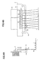
A specific configuration of the plasma irradiation device (surface reforming device) 108 is shown in FIG. 3. FIG. 3A is a vertical longitudinal sectional view of the device in the case of viewing from a direction orthogonal to the sheet conveyance direction. FIG. 3B is a detailed view of a plasma irradiation nozzle 153.
In surface reformation by means of plasma irradiation, high voltage (for example, 2 to 10 kV) is applied to two electrodes 151 and 152, followed by application to the two electrodes (1 cm to 20 cm as a distance) in a range of 10 μA to 50 mA, then the air is flowed between the electrodes, so that oxygen or the like in the air generates a radical and radical oxygen attacks (reacts with a part with C-H binding in a resin) a surface of a toner (for example, a major component of the toner is a resin such as polyester and styrene acryl), thereby generating on the surface of the toner T a hydrophilic group such as an OH group and a carbonyl group.
On the other hand, on the surface of the recording sheet P, many OH groups (OH group belonging to cellulose serving as a major component of paper) are present, and it is thus possible to increase adhesiveness to the recording sheet P.
A surface treatment device takes outside air into the device by means of a fan 154 (FIG. 3A) to deliver plasma to a surface of a toner.
Note that, a plasma generator in atmospheric pressure includes, for example, a plasma irradiation surface reforming device PS-601SW (manufactured by Wedge Co., Ltd.) and an atmospheric pressure plasma irradiation device disclosed in Japanese Patent Application Laid-open No. 2009-87697 and the like, and may have any configuration in which such a plasma irradiation device makes it possible to introduce a hydrophilic group onto a surface of a toner.
For example, it is described in a catalog of PS-601SW that wettability is improved (higher numerical values cause a hydrophilic property to be increased, thus having favorable wettability, thereby easily having diffusion (adherence) to a sheet) by a test method according to JIS K6768 (test method of plastic wettability). As a specific example, for wettability before and after surface treatment, polyethylene (PE) is improved from 31 mN/m to 70 mN/m, and in the same manner, acryl is improved from 38 mN/m to 70 mN/m, and the like, as well as improving wettability for many other resins, and besides, it is also possible to improve wettability of a polyester resin and an acrylic resin which are major components of a toner by applying surface treatment as with these PE and acryl.
FIG. 4 is a view showing a configuration of the laser irradiation portion 41. FIG. 4A is a cross-sectional view of the laser irradiation portion 41 along a conveyance direction of the recording sheet P, and FIG. 4B is a front view of the laser irradiation portion 41 in the case of viewing from the conveyance direction of the recording sheet P.
The laser irradiation portion 41 is a device for emitting a laser beam. In the present embodiment, in the laser irradiation portion 41, a plurality of semiconductor laser elements 213 are provided across a width direction of the recording sheet conveyor belt 103 for fixation.
The plurality of semiconductor laser elements 213 serving as a semiconductor laser element array are arrayed in a line in a direction orthogonal to the recording sheet conveyance direction having equal space from the surface of the recording sheet conveyor belt 103, respectively. That is, the semiconductor laser element array is disposed parallel to the surface of the recording sheet conveyor belt 103.
A laser beam that is emitted from the semiconductor laser element 213 has a cross-section in an approximately true circle shape vertical to an emission direction that is a direction to which the laser beam moves.
Each of the semiconductor laser elements 213 is provided so that each emission direction of a laser beam to be emitted is all the same, so as to be a direction vertical to a direction in which the semiconductor laser elements 213 are arrayed.
As the semiconductor laser element 213, one having a wavelength of a laser beam to be emitted that is 400 nm to 1000 nm is arbitrarily selectable.
Each semiconductor laser element 213 is provided on each silicon substrate 212 that is formed of silicon.
On the silicon substrate 212, an unillustrated control circuit and a light receiving element 214 are monolithically formed.
The light receiving element 214 is photodiode for a monitor.
The control circuit controls voltage that is applied to the semiconductor laser element 213 based on a signal that is input from the light receiving element 214 so that output of a laser beam is changed and kept constant.
The control circuit and the semiconductor laser element 213 are electrically connected to each other via an unillustrated electrode and a bonding wire.
Additionally, on the silicon substrate 212, a temperature sensor 215 such as a thermistor is provided in order to measure temperature of each semiconductor laser element 213.
The control circuit controls voltage that is applied to the semiconductor laser element 213 based on temperature data that is detected by the temperature sensor 215.
The silicon substrate 212 is provided on a ceramic substrate 211 on the surface opposite to the surface on which the semiconductor laser element 213 is provided. A not-shown electrode on the ceramic substrate 211 and a not-shown electrode on the silicon substrate 212 are electrically connected to each other by wire bonding or the like.
Further, in the ceramic substrate 211, a heat sink 218 is provided on the surface opposite to the surface on which the silicon substrate 212 is provided.
A lens array 216 is provided on a downstream side in an irradiation direction of the semiconductor laser element 213.
The lens array 216 includes the same number of a convex lens 217 a as a total number of semiconductor laser elements 213, and a lens holder 217 b for holding the convex lens 217 a.
The lens array 216 is configured so that a laser beam emitted from each of the semiconductor laser elements 213 enters each of the convex lenses 217 a, respectively.
As described above, the laser irradiation section 41 in the present embodiment is a semiconductor laser element array in which a plurality of semiconductor laser elements 213 are arrayed in a line in a direction vertical to the recording sheet conveyance direction (width direction of the recording sheet conveyor belt 103 for fixation) having equal space from the surface of the recording sheet conveyor belt 103 for fixation, respectively. Namely, the semiconductor laser element array is disposed parallel to the surface of the recording sheet conveyor belt 103 for fixation.
For example, in the case of irradiating an entire surface of the recording sheet P with light by one laser beam source, it is needed to scan with a laser beam in a width direction of the recording sheet P. Accordingly, it takes time for a fixing process, thus having a limitation in fixing at high speed. Furthermore, scanning of the laser beam causes the device to be complicated and have cost increases.
Whereas, the laser irradiation portion 41 is configured to be the semiconductor laser element array so that it is not needed to scan with a laser beam in the width direction of the recording sheet P, thus making it possible to fix at high speed with a simple device configuration.
Moreover, rather than high output with one laser beam source, high output in a configuration in which a plurality of semiconductor laser elements 213 are provided makes an area of a heat radiation portion in the laser irradiation portion 41 larger. It is possible to improve a heat transfer efficiency to the heat sink 218 which is the heat radiation portion.
The recording sheet P has an unfixed toner image that is formed thereon with the visible image formation unit 50, and is conveyed to the fixing device 40.
The surface reforming device 108 of the fixing device 40 performs surface reformation for the surface of the toner T on the recording sheet P by, for example, plasma irradiation or the like, thereby generating a polar group of a hydrophilic property on the surface of the toner.
Next, the recording sheet P is conveyed to the laser irradiation portion 41 by the recording sheet conveyance device 100 to be irradiated with a laser, in which the toner T is fused to be fixed to the recording sheet.
The toner T on the recording sheet P is subjected to surface reforming treatment, thus having increased affinity (adhesion force) with the recording sheet P, so that it is possible to secure favorable fixability without pressing.
Additionally, as a noncontact-fixing method, heating is performed by light irradiation so that there is no need for warm-up of a heating portion, and it is possible to heat and fuse instantly only at the time of desired fixation to effectively perform fixation.
Note that, noncontact fixation by means of a laser is performed in the embodiment, however, noncontact fixation may be performed by means of light irradiation with a flash lamp, an LED and the like, oven heating and the like.
However, since a laser has less light diffusion, a largest amount of light is able to be condensed by the combined use of a laser and a condensing lens so that it is possible to bring maximum light intensity (light output per unit area: W/mm2), thus making it possible to effectively irradiate with light.
Further, in the case of laser irradiation, it is possible to selectively heat only a location where a toner is present, and the toner is able to be further effectively heated.
Additionally, a semiconductor laser is used among lasers so that it is possible to reduce the cost because of lower cost of elements compared to use of a CO2 laser (carbon dioxide laser) and a YAG laser (solid-state laser using yttrium/aluminum/garnet).
For example, in the case of irradiating an entire surface of a sheet with light by one laser beam source, it is needed to scan with a laser in a sheet conveyance direction and a vertical direction other than a conveyance direction of the sheet. Accordingly, it takes time for a fixing process, thus having a limitation in fixing at high speed. Furthermore, scanning of a laser causes the device to be complicated and have cost increases. On the other hand, lasers are disposed in a line in the sheet conveyance direction and the vertical direction so that it is not necessary to scan with a laser in the sheet conveyance direction and the vertical direction, thus enabling use in a most basic configuration and also fixation at high speed.
Hereinbefore, the embodiments of the present invention have been described in detail with reference to the drawings, however, a specific configuration is not limited to such embodiments, and design and the like without departing from the spirit of the present invention may be made within the scope of the appended claims.

Claims (5)

What is claimed is:
1. A fixing device for fixing an unfixed toner image in noncontact while conveying a recording member on which the toner image is formed, comprising:
a surface reforming portion for reforming a surface of the toner on the recording member so as to increase affinity to the recording member in heating and fusing; and
a noncontact fixing portion for heating and fusing in noncontact the toner whose surface is reformed, and
wherein the recording member is paper, and
wherein the surface reforming portion is arranged on an upstream side of a conveyance direction of the recording member with respect to the noncontact fixing portion, and the surface reforming portion is configured to increase the affinity to the recording member by generating a polar group of a hydrophilic property on the surface of the toner, and
wherein the noncontact fixing portion vertically irradiates light onto the toner whose surface is reformed, thereby fixing a toner image.
2. The fixing device according to claim 1, wherein
the noncontact fixing portion uses a laser beam.
3. The fixing device according to claim 2, wherein
the noncontact fixing portion uses a semiconductor laser.
4. The fixing device according to claim 3, wherein
the noncontact fixing portion includes a laser array in which a plurality of semiconductor laser elements are disposed in an array in a direction orthogonal to a conveyance direction of the recording member.
5. An image forming apparatus comprising the fixing device according to claim 1.
US13/332,584 2011-02-03 2011-12-21 Fixing device and image forming apparatus including the same Active 2032-09-25 US8824947B2 (en)

Applications Claiming Priority (2)

Application Number Priority Date Filing Date Title
JP2011022008A JP5367738B2 (en) 2011-02-03 2011-02-03 Fixing apparatus and image forming apparatus having the same
JP2011-022008 2011-02-03

Publications (2)

Publication Number Publication Date
US20120201584A1 US20120201584A1 (en) 2012-08-09
US8824947B2 true US8824947B2 (en) 2014-09-02

Family

ID=46587366

Family Applications (1)

Application Number Title Priority Date Filing Date
US13/332,584 Active 2032-09-25 US8824947B2 (en) 2011-02-03 2011-12-21 Fixing device and image forming apparatus including the same

Country Status (3)

Country Link
US (1) US8824947B2 (en)
JP (1) JP5367738B2 (en)
CN (1) CN102629097A (en)

Cited By (1)

* Cited by examiner, † Cited by third party
Publication number Priority date Publication date Assignee Title
US20180231912A1 (en) * 2015-12-24 2018-08-16 Canon Kabushiki Kaisha Image forming apparatus

Families Citing this family (3)

* Cited by examiner, † Cited by third party
Publication number Priority date Publication date Assignee Title
CN104614964B (en) * 2013-11-01 2017-11-24 东友科技股份有限公司 Fixing device and its roller
DE102014106040A1 (en) 2014-04-30 2015-11-05 Océ Printing Systems GmbH & Co. KG Intermediate fixation of liquid toner by high-energy plasma
JP6565210B2 (en) * 2015-02-23 2019-08-28 富士ゼロックス株式会社 Image forming apparatus and surface treatment apparatus

Citations (34)

* Cited by examiner, † Cited by third party
Publication number Priority date Publication date Assignee Title
US3676350A (en) * 1970-02-03 1972-07-11 Eastman Kodak Co Glow discharge polymerization coating of toners for electrophotography
US3849165A (en) * 1971-06-03 1974-11-19 Eastman Kodak Co Liquid electrographic development process
US3944783A (en) * 1974-10-18 1976-03-16 Xerox Corporation High efficiency non-cavity radiant method and apparatus
US3980863A (en) * 1973-11-16 1976-09-14 Wifo Wissenschaftliches Forschungs-Institut A.G. Electrophotographic copying machines
US4034186A (en) * 1975-03-15 1977-07-05 Agfa-Gevaert, Aktiengesellschaft Method and arrangement for preventing sheets from charring in copying machines
US4049947A (en) * 1975-03-15 1977-09-20 Agfa-Gevaert, A.G. Method and arrangement for protecting sheets from charring in copying machines
US4456370A (en) * 1982-11-08 1984-06-26 Xerox Corporation Charge control system
US4794422A (en) * 1986-06-09 1988-12-27 Xerox Corporation Electrophotographic reproduction machine with document exposure system directly coupled to ac line input
US4972030A (en) * 1988-08-22 1990-11-20 Air Products And Chemicals, Inc. Abrasion resistant composite coating material and process for making the same
JPH0422971A (en) 1990-05-18 1992-01-27 Ricoh Co Ltd Toner
JPH07191560A (en) 1993-12-27 1995-07-28 Sharp Corp Laser fixing device
JPH1138802A (en) 1997-07-15 1999-02-12 Fuji Xerox Co Ltd Heat fixing device
JPH11202671A (en) 1998-01-16 1999-07-30 Canon Inc Image recorder
US6461782B1 (en) * 1998-03-11 2002-10-08 Sanyo Chemical Industries, Ltd. Toner and method for image formation
US20020146650A1 (en) * 1999-12-17 2002-10-10 Noriyuki Kokeguchi Photographic processing element and image forming method by the use thereof
US6587665B2 (en) * 2000-12-22 2003-07-01 Nexpress Solutions Llc Digital printer or copier machine and processes for fixing a toner image
US6665516B2 (en) * 2000-12-22 2003-12-16 Nexpress Solutions Llc Fixation device for fixation of toner material
US20040006158A1 (en) * 2002-06-18 2004-01-08 Fuji Photo Film Co., Ltd. Oil based ink composition for inkjet printer
US20040006159A1 (en) * 2002-06-28 2004-01-08 Fuji Photo Film Co., Ltd. Oil based ink composition for inkjet printer, electrophotographic liquid developer and production process of colored resin particle
US20040060465A1 (en) * 2002-09-05 2004-04-01 Fuji Photo Film Co., Ltd. Planographic printing plate precursor
US20040067434A1 (en) * 2002-09-18 2004-04-08 Fuji Photo Film Co., Ltd. Method of graft polymerization and variety of materials utilizing the same as well as producing method thereof
JP2005055516A (en) 2003-08-06 2005-03-03 Canon Inc Laser fixing device
US20070014584A1 (en) * 2005-07-13 2007-01-18 Xerox Corporation Calibration apparatus and method for charging unit of image forming device
US20070280758A1 (en) * 2006-06-01 2007-12-06 Eastman Kodak Company Chilled finish roller system and method
US20070287085A1 (en) * 2006-06-07 2007-12-13 Fuji Xerox Co., Ltd. Electrophotographic photoreceptor, and process cartridge and image forming apparatus using the same
US20080095558A1 (en) * 2004-09-10 2008-04-24 Martin Schleusener Method for Uv Curing Toner Images Applied to an Image Support in an Electrographic Printing or Copying Device
US20080101832A1 (en) 2006-10-25 2008-05-01 Fuji Xerox Co., Ltd. Image forming apparatus and fixing device
US20090175663A1 (en) * 2006-06-09 2009-07-09 Canon Kabushiki Kaisha Image fixing method, method for producing record product using such method, and image recording apparatus
US20090290907A1 (en) * 2008-02-07 2009-11-26 Canon Kabushiki Kaisha Electrophotographic developing member, process for its production, electrophotographic process cartridge and electrophotographic image forming apparatus
JP2010217731A (en) 2009-03-18 2010-09-30 Sharp Corp Fixing device and image forming apparatus including the same
US20100296979A1 (en) * 2007-09-28 2010-11-25 Masaru Hori Plasma generator
US20110116851A1 (en) * 2009-11-16 2011-05-19 Atsushi Tanaka Laser fixing device and image forming apparatus including the laser fixing device
US20110222935A1 (en) * 2010-03-12 2011-09-15 Fuji Xerox Co., Ltd. Fixing device and image forming apparatus using the same
US20130130172A1 (en) * 2011-11-17 2013-05-23 Thomas Nathaniel Tombs Deinking a print

Family Cites Families (1)

* Cited by examiner, † Cited by third party
Publication number Priority date Publication date Assignee Title
CA2504791C (en) * 2005-04-21 2014-01-14 Shawcor Ltd. Bondably coated metallic member

Patent Citations (36)

* Cited by examiner, † Cited by third party
Publication number Priority date Publication date Assignee Title
US3676350A (en) * 1970-02-03 1972-07-11 Eastman Kodak Co Glow discharge polymerization coating of toners for electrophotography
US3849165A (en) * 1971-06-03 1974-11-19 Eastman Kodak Co Liquid electrographic development process
US3980863A (en) * 1973-11-16 1976-09-14 Wifo Wissenschaftliches Forschungs-Institut A.G. Electrophotographic copying machines
US3944783A (en) * 1974-10-18 1976-03-16 Xerox Corporation High efficiency non-cavity radiant method and apparatus
US4034186A (en) * 1975-03-15 1977-07-05 Agfa-Gevaert, Aktiengesellschaft Method and arrangement for preventing sheets from charring in copying machines
US4049947A (en) * 1975-03-15 1977-09-20 Agfa-Gevaert, A.G. Method and arrangement for protecting sheets from charring in copying machines
US4456370A (en) * 1982-11-08 1984-06-26 Xerox Corporation Charge control system
US4794422A (en) * 1986-06-09 1988-12-27 Xerox Corporation Electrophotographic reproduction machine with document exposure system directly coupled to ac line input
US4972030A (en) * 1988-08-22 1990-11-20 Air Products And Chemicals, Inc. Abrasion resistant composite coating material and process for making the same
JPH0422971A (en) 1990-05-18 1992-01-27 Ricoh Co Ltd Toner
JPH07191560A (en) 1993-12-27 1995-07-28 Sharp Corp Laser fixing device
JPH1138802A (en) 1997-07-15 1999-02-12 Fuji Xerox Co Ltd Heat fixing device
JPH11202671A (en) 1998-01-16 1999-07-30 Canon Inc Image recorder
US6461782B1 (en) * 1998-03-11 2002-10-08 Sanyo Chemical Industries, Ltd. Toner and method for image formation
US20020146650A1 (en) * 1999-12-17 2002-10-10 Noriyuki Kokeguchi Photographic processing element and image forming method by the use thereof
US6587665B2 (en) * 2000-12-22 2003-07-01 Nexpress Solutions Llc Digital printer or copier machine and processes for fixing a toner image
US6665516B2 (en) * 2000-12-22 2003-12-16 Nexpress Solutions Llc Fixation device for fixation of toner material
US20040006158A1 (en) * 2002-06-18 2004-01-08 Fuji Photo Film Co., Ltd. Oil based ink composition for inkjet printer
US20040006159A1 (en) * 2002-06-28 2004-01-08 Fuji Photo Film Co., Ltd. Oil based ink composition for inkjet printer, electrophotographic liquid developer and production process of colored resin particle
US20040060465A1 (en) * 2002-09-05 2004-04-01 Fuji Photo Film Co., Ltd. Planographic printing plate precursor
US20040067434A1 (en) * 2002-09-18 2004-04-08 Fuji Photo Film Co., Ltd. Method of graft polymerization and variety of materials utilizing the same as well as producing method thereof
JP2005055516A (en) 2003-08-06 2005-03-03 Canon Inc Laser fixing device
US20080095558A1 (en) * 2004-09-10 2008-04-24 Martin Schleusener Method for Uv Curing Toner Images Applied to an Image Support in an Electrographic Printing or Copying Device
US20070014584A1 (en) * 2005-07-13 2007-01-18 Xerox Corporation Calibration apparatus and method for charging unit of image forming device
US20070280758A1 (en) * 2006-06-01 2007-12-06 Eastman Kodak Company Chilled finish roller system and method
US20090239172A1 (en) * 2006-06-01 2009-09-24 Andrew Ciaschi Chilled finish roller system and method
US20070287085A1 (en) * 2006-06-07 2007-12-13 Fuji Xerox Co., Ltd. Electrophotographic photoreceptor, and process cartridge and image forming apparatus using the same
US20090175663A1 (en) * 2006-06-09 2009-07-09 Canon Kabushiki Kaisha Image fixing method, method for producing record product using such method, and image recording apparatus
JP2008107576A (en) 2006-10-25 2008-05-08 Fuji Xerox Co Ltd Image forming apparatus, and fixing device
US20080101832A1 (en) 2006-10-25 2008-05-01 Fuji Xerox Co., Ltd. Image forming apparatus and fixing device
US20100296979A1 (en) * 2007-09-28 2010-11-25 Masaru Hori Plasma generator
US20090290907A1 (en) * 2008-02-07 2009-11-26 Canon Kabushiki Kaisha Electrophotographic developing member, process for its production, electrophotographic process cartridge and electrophotographic image forming apparatus
JP2010217731A (en) 2009-03-18 2010-09-30 Sharp Corp Fixing device and image forming apparatus including the same
US20110116851A1 (en) * 2009-11-16 2011-05-19 Atsushi Tanaka Laser fixing device and image forming apparatus including the laser fixing device
US20110222935A1 (en) * 2010-03-12 2011-09-15 Fuji Xerox Co., Ltd. Fixing device and image forming apparatus using the same
US20130130172A1 (en) * 2011-11-17 2013-05-23 Thomas Nathaniel Tombs Deinking a print

Cited By (2)

* Cited by examiner, † Cited by third party
Publication number Priority date Publication date Assignee Title
US20180231912A1 (en) * 2015-12-24 2018-08-16 Canon Kabushiki Kaisha Image forming apparatus
US10261435B2 (en) * 2015-12-24 2019-04-16 Canon Kabushiki Kaisha Image forming apparatus that controls rotation of a feeding belt and an irradiating state of an ultraviolet irradiating portion

Also Published As

Publication number Publication date
US20120201584A1 (en) 2012-08-09
JP5367738B2 (en) 2013-12-11
CN102629097A (en) 2012-08-08
JP2012163626A (en) 2012-08-30

Similar Documents

Publication Publication Date Title
US7738805B2 (en) Xerography methods and systems employing addressable fusing of unfused toner image
US8452220B2 (en) Laser fixing device
US8824947B2 (en) Fixing device and image forming apparatus including the same
US8433231B2 (en) Laser fixing device and image forming apparatus including the laser fixing device
KR20190072977A (en) Heater for fusing device having pairs of heating element and fusing device using the heater
US7805090B2 (en) Fuser assemblies, xerographic apparatuses and methods of fusing toner on media in xerographic apparatuses
JP2012042698A (en) Fixing device and image forming apparatus
US9519249B2 (en) Fixing device and image forming apparatus
US8706015B2 (en) Fixing device including fixing belt and image forming apparatus using the same
JP2006350241A (en) Fixing device and image forming apparatus
US20210286298A1 (en) Image forming device
JP5259471B2 (en) Fixing apparatus and image forming apparatus using the same
US8000642B2 (en) Fixing device and image forming apparatus including the fixing device using a dielectric material heated by an electric field
JP6264199B2 (en) Image forming system
US7742733B2 (en) Fuser assemblies, xerographic apparatuses and methods of fusing toner on media
US20120093553A1 (en) Optical fixing device and image forming apparatus
JP7033883B2 (en) Heater and image forming device
JP5402434B2 (en) Fixing apparatus and image forming apparatus
JP4950576B2 (en) Fixing device
JP2019078817A (en) Heater and image forming apparatus
JP2008151857A (en) Heat fixing device and image forming apparatus
JP2011085785A (en) Fixing device and image forming apparatus using the same
JP2006085063A (en) Fixing device
JP2013092640A (en) Laser fixing device
JP2001215816A (en) Printer

Legal Events

Date Code Title Description
AS Assignment

Owner name: SHARP KABUSHIKI KAISHA, JAPAN

Free format text: ASSIGNMENT OF ASSIGNORS INTEREST;ASSIGNOR:MAEDA, TOMOHIRO;REEL/FRAME:027427/0585

Effective date: 20111208

STCF Information on status: patent grant

Free format text: PATENTED CASE

FEPP Fee payment procedure

Free format text: PAYOR NUMBER ASSIGNED (ORIGINAL EVENT CODE: ASPN); ENTITY STATUS OF PATENT OWNER: LARGE ENTITY

MAFP Maintenance fee payment

Free format text: PAYMENT OF MAINTENANCE FEE, 4TH YEAR, LARGE ENTITY (ORIGINAL EVENT CODE: M1551)

Year of fee payment: 4

MAFP Maintenance fee payment

Free format text: PAYMENT OF MAINTENANCE FEE, 8TH YEAR, LARGE ENTITY (ORIGINAL EVENT CODE: M1552); ENTITY STATUS OF PATENT OWNER: LARGE ENTITY

Year of fee payment: 8