US8823960B2 - Setting value management apparatus, setting value management method, and computer-readable medium - Google Patents
Setting value management apparatus, setting value management method, and computer-readable medium Download PDFInfo
- Publication number
- US8823960B2 US8823960B2 US13/529,281 US201213529281A US8823960B2 US 8823960 B2 US8823960 B2 US 8823960B2 US 201213529281 A US201213529281 A US 201213529281A US 8823960 B2 US8823960 B2 US 8823960B2
- Authority
- US
- United States
- Prior art keywords
- configuration data
- image forming
- forming apparatus
- function
- setting value
- Prior art date
- Legal status (The legal status is an assumption and is not a legal conclusion. Google has not performed a legal analysis and makes no representation as to the accuracy of the status listed.)
- Expired - Fee Related, expires
Links
Images


Classifications
-
- H—ELECTRICITY
- H04—ELECTRIC COMMUNICATION TECHNIQUE
- H04N—PICTORIAL COMMUNICATION, e.g. TELEVISION
- H04N1/00—Scanning, transmission or reproduction of documents or the like, e.g. facsimile transmission; Details thereof
- H04N1/00127—Connection or combination of a still picture apparatus with another apparatus, e.g. for storage, processing or transmission of still picture signals or of information associated with a still picture
- H04N1/00344—Connection or combination of a still picture apparatus with another apparatus, e.g. for storage, processing or transmission of still picture signals or of information associated with a still picture with a management, maintenance, service or repair apparatus
-
- H—ELECTRICITY
- H04—ELECTRIC COMMUNICATION TECHNIQUE
- H04N—PICTORIAL COMMUNICATION, e.g. TELEVISION
- H04N1/00—Scanning, transmission or reproduction of documents or the like, e.g. facsimile transmission; Details thereof
- H04N1/00962—Input arrangements for operating instructions or parameters, e.g. updating internal software
- H04N1/0097—Storage of instructions or parameters, e.g. customised instructions or different parameters for different user IDs
-
- H—ELECTRICITY
- H04—ELECTRIC COMMUNICATION TECHNIQUE
- H04N—PICTORIAL COMMUNICATION, e.g. TELEVISION
- H04N1/00—Scanning, transmission or reproduction of documents or the like, e.g. facsimile transmission; Details thereof
- H04N1/00962—Input arrangements for operating instructions or parameters, e.g. updating internal software
- H04N1/00973—Input arrangements for operating instructions or parameters, e.g. updating internal software from a remote device, e.g. receiving via the internet instructions input to a computer terminal
-
- G—PHYSICS
- G06—COMPUTING OR CALCULATING; COUNTING
- G06F—ELECTRIC DIGITAL DATA PROCESSING
- G06F3/00—Input arrangements for transferring data to be processed into a form capable of being handled by the computer; Output arrangements for transferring data from processing unit to output unit, e.g. interface arrangements
- G06F3/12—Digital output to print unit, e.g. line printer, chain printer
- G06F3/1201—Dedicated interfaces to print systems
- G06F3/1223—Dedicated interfaces to print systems specifically adapted to use a particular technique
- G06F3/1229—Printer resources management or printer maintenance, e.g. device status, power levels
- G06F3/1231—Device related settings, e.g. IP address, Name, Identification
Definitions
- the present invention relates to a setting value management apparatus, setting value management method, and computer-readable medium. Particularly, the present invention relates to a technique of reflecting, in another image forming apparatus, configuration data serving as setting values for switching the operation of an image forming apparatus.
- Some image forming apparatuses store configuration data serving as setting values for switching the operation. Configuration data is stored in the storage device of each image forming apparatus. To change configuration data of all image forming apparatuses, setting needs to be executed for the number of image forming apparatuses. To omit this cumbersome operation, there is a technique for setting configuration data at once in a plurality of image forming apparatuses from an information processing apparatus.
- Some image forming apparatuses include a preset button for storing setting values in advance. Setting data of this preset button is also part of configuration data.
- the setting range of configuration data often differs between the respective models.
- the settable range is wide for a high-end model physically having a large memory capacity and narrow for a low-end model having a small memory capacity.
- configuration data is prepared for each model. Every time configuration data is reflected from a given model to another, the administrator needs to change/delete configuration data exceeding the setting range.
- an image forming apparatus which refers to it rejects settings exceeding the range or makes settings only within the setting range, and cannot reflect the same settings.
- a transmission destination count registered for the ScanToSend preset button a high-end model allows registering 100 destinations, and a low-end model allows registering up to 50 destinations.
- untransmitted data is often saved in a memory such as a static RAM.
- the static RAM is generally expensive, so the above limitation is placed. In this case, the settings of the ScanToSend preset button of the high-end model in which 70 destinations are registered cannot be reflected in the low-end model.
- a setting value management apparatus which manages configuration data of a plurality of image forming apparatuses, comprising: a holding unit configured to hold configuration data defined for respective models of the plurality of image forming apparatuses or respective image forming apparatuses; an acquisition unit configured to acquire configuration data of a first image forming apparatus from the holding unit; a determination unit configured to determine whether a value defined in the acquired configuration data of the first image forming apparatus exceeds a range settable for a function of a second image forming apparatus; and a generation unit configured to, when the determination unit determines that the value defined in the acquired configuration data of the first image forming apparatus exceeds the settable range, newly generate configuration data to implement an operation to be executed based on the value defined in the configuration data of the first image forming apparatus by combining at least one other function executable by the second image forming apparatus.
- a setting value management method of managing configuration data of a plurality of image forming apparatuses comprising the steps of: holding, in a storage unit, configuration data defined for respective models of the plurality of image forming apparatuses or respective image forming apparatuses; acquiring configuration data of a first image forming apparatus from the storage unit; determining whether a value defined in the acquired configuration data of the first image forming apparatus exceeds a range settable for a function of a second image forming apparatus; and generating, when the value defined in the acquired configuration data of the first image forming apparatus is determined in the determination step to exceed the settable range, newly configuration data to implement an operation to be executed based on the value defined in the configuration data of the first image forming apparatus by combining at least one other function executable by the second image forming apparatus.
- a non-transitory computer-readable medium storing a program for causing a computer to function as a holding unit configured to hold configuration data defined for respective models of a plurality of image forming apparatuses or respective image forming apparatuses, an acquisition unit configured to acquire configuration data of a first image forming apparatus from the holding unit, a determination unit configured to determine whether a value defined in the acquired configuration data of the first image forming apparatus exceeds a range settable for a function of a second image forming apparatus, and a generation unit configured to, when the determination unit determines that the value defined in the acquired configuration data of the first image forming apparatus exceeds the settable range, newly generate configuration data to implement an operation to be executed based on the value defined in the configuration data of the first image forming apparatus by combining at least one other function executable by the second image forming apparatus.
- configuration data of an image forming apparatus of a given model when configuration data of an image forming apparatus of a given model is imported to an image forming apparatus of a different model and exceeds the settable range, it can be set to perform the same behavior.
- FIG. 1 is a block diagram showing a network configuration
- FIG. 2 is a block diagram showing a hardware arrangement
- FIG. 3 is a block diagram showing a software arrangement
- FIGS. 4A and 4B are tables exemplifying a model-specific setting value schema
- FIG. 5 is a table exemplifying virtual configuration data
- FIGS. 6A , 6 B, and 6 C are tables exemplifying device component data
- FIGS. 7A and 7B are tables exemplifying virtual configuration data
- FIGS. 8A and 8B are tables exemplifying virtual configuration data
- FIGS. 9A and 9B are tables exemplifying virtual configuration data
- FIG. 10 is a flowchart for explaining processing by an image forming apparatus
- FIG. 11 is a flowchart for explaining processing by a setting value management service
- FIG. 12 is a flowchart for explaining processing by the setting value management service
- FIG. 13 is a flowchart for explaining processing by the setting value management service
- FIG. 14 is a flowchart for explaining processing by the setting value management service.
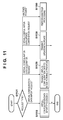
- FIG. 15 is a flowchart for explaining processing by the setting value management service.
- Configuration data is setting value information for switching the operation of an image forming apparatus. More specifically, the configuration data contains the setting values of various operations in the image forming apparatus.
- An example is the default value of imposition for a copy job. When imposition is set to “1in1”, one page is printed on one sheet as a result of copying. When imposition is set to “2in1”, two pages are printed on one sheet as a result of copying.
- Device component data is data representing device components in an image forming apparatus.
- An example is data representing whether the image forming apparatus includes a facsimile unit.
- the device component data contains a model code for uniquely identifying the model of the image forming apparatus, and the version of running firmware.
- a model-specific setting value schema is data which defines the schema of configuration data held in an image forming apparatus of a specific model.
- the schema is data which defines the conventions and evaluation of configuration data.
- the model-specific setting value schema contains the setting value identifier of each configuration data, default value, range, and condition to validate data. Since implementable functions change depending on the model of each image forming apparatus, held configuration data has a difference depending on the model. Hence, the setting value schema is prepared for each model.
- a virtual device is a data group of actual devices held in a server computer group. More specifically, the virtual device contains at least device component data and configuration data. To the contrary, an actual device corresponds to a physical device (for example, image forming apparatus).
- Device component data contained in a virtual device will be called virtual device component data.
- Configuration data contained in the virtual device will be called virtual configuration data.
- Device component data held in an actual device will be called actual device component data.
- Configuration data held in the actual device will be called actual configuration data.
- FIG. 1 is a block diagram exemplifying the network configuration of a system according to the embodiment.
- Image forming apparatuses 101 A, 101 B, and 101 C are image forming apparatuses managed in the present invention.
- Each image forming apparatus in a user environment 100 can access Internet 104 via a network 106 .
- a terminal device 102 D is a computer operable by a user in the user environment 100 , and can access the Internet 104 via the network 106 .
- a terminal device 102 E is a computer operable by a serviceman who manages the image forming apparatuses 101 A, 101 B, and 101 C. The terminal device 102 E can access the Internet 104 .
- a terminal device 102 F is a computer operable by a person in charge of management who belongs to an image forming apparatus vendor. The terminal device 102 F can access the Internet 104 .
- the terminal device 102 D and the image forming apparatuses 101 A, 101 B, and 101 C belong to the user environment 100 , and are connected to each other via the network 106 .
- the Internet 104 is a network capable of digital communication on a public line.
- a server computer group 105 is a server group which provides services via the Internet 104 .
- the network 106 connects the apparatuses to each other in the user environment 100 , and enables digital communication.
- a serviceman environment 110 is an environment where the serviceman for an image forming apparatus manages, for example, image forming apparatuses belonging to the user environment 100 by using the terminal device 102 E.
- An image forming apparatus vendor environment 120 is an environment where the person in charge of management in a vendor which produces image forming apparatuses maintains data necessary to manage, for example, image forming apparatuses belonging to the user environment 100 by using the terminal device 102 F.
- FIG. 2 is a block diagram exemplifying a hardware arrangement according to the embodiment.
- a server computer 211 H has the same hardware arrangement as that of a server computer 211 G, so these hardware arrangements will be explained collectively.
- a CPU 201 executes programs stored in a storage device, and controls various processes in a mounted apparatus.
- a nonvolatile memory 202 is formed from a ROM (Read Only Memory), and stores programs and data necessary at the initial stage in device activation processing.
- a volatile memory 203 is formed from a RAM (Random Access Memory) and used as a temporary storage location for programs and data.
- An auxiliary storage device 204 is formed from a large-capacity storage device such as a hard disk or RAM drive.
- the auxiliary storage device 204 saves a large amount of data and holds program execution codes.
- the auxiliary storage device 204 stores data which need to be held for a long term, compared to the volatile memory 203 .
- the auxiliary storage device 204 is a nonvolatile storage device and can keep storing data even after power-off.
- a display 205 is a display unit for presenting information to a user. In this specification, the user assumes both a user and serviceman.
- An input device 206 is a device for receiving a selection instruction from a user, and transmitting it to a program via an internal bus 210 .
- a network communication device 207 is a device for communicating with another information processing apparatus via a network.
- a facsimile unit 208 is a hardware unit for transmitting, to another information device via the network 106 , image data formed by the image forming apparatus 101 or image data stored in the auxiliary storage device 204 .
- the facsimile unit 208 is an option and may not be mounted depending on the apparatus.
- a printer engine 209 is a unit which prints, on a paper medium, image data formed by the image forming apparatus 101 or image data stored in the auxiliary storage device 204 .
- the internal bus 210 is a communication bus which connects the CPU 201 , nonvolatile memory 202 , volatile memory 203 , auxiliary storage device 204 , display 205 , input device 206 , and network communication device 207 so that they can communicate with each other in the image forming apparatus 101 .
- the server computer 211 G is one of server computers which form the server computer group 105 .
- the internal bus 210 G is a communication bus which connects the CPU 201 G, nonvolatile memory 202 G, volatile memory 203 G, auxiliary storage device 204 G, and network communication device 207 G of the server computer 211 G so that they can communicate with each other in the server computer 211 G.
- a network 220 connects a plurality of server computers in the server computer group 105 to each other to enable high-speed communication between them.
- FIG. 3 is a block diagram exemplifying a software arrangement according to the embodiment. The respective units of the image forming apparatus 101 will be explained first.
- An actual configuration data holding unit 301 holds configuration data of the image forming apparatus 101 in the auxiliary storage device 204 A serving as a storage unit.
- the image forming apparatus 101 switches the operation behavior based on actual configuration data held in the actual configuration data holding unit 301 .
- An actual configuration data update unit 302 updates actual configuration data held in the actual configuration data holding unit 301 .
- the actual configuration data update unit 302 updates actual configuration data using virtual configuration data acquired by a virtual configuration data reception unit 303 . Note that the actual configuration data update unit 302 updates actual configuration data only when a virtual configuration data update confirmation unit 319 confirms that virtual configuration data has been updated.
- the virtual configuration data reception unit 303 invokes a virtual configuration data acquisition unit 318 of a setting value management service 310 (to be described later), and receives virtual configuration data.
- an address for invoking the virtual configuration data acquisition unit 318 is an address held in the actual configuration data holding unit 301 .
- a setting value identifier 402 is “device settings.cloud_address”, “http://oanon.com/config” is set as actual configuration data in a corresponding default value 403 .
- the virtual configuration data acquisition unit 318 accesses “http://oanon.com/config”.
- the setting value management service 310 is a service which provides a function of managing configuration data of the image forming apparatus 101 .
- the above-described server computer group 105 provides the setting value management service 310 .
- the two server computers 211 G and 211 H are connected via the network 220 in the server computer group 105 of FIG. 2 .
- the arrangement is not limited to this.
- the setting value management service 310 may be provided by one server computer or three or more server computers.
- the setting value management service 310 holds a plurality of units, which will be described below.
- a virtual device holding unit 311 stores data held in a virtual device.
- Data held in a virtual device contains virtual device component data and virtual configuration data.
- the virtual device holding unit 311 stores the device identifier of each virtual devices in correspondence with each data.
- the virtual device holding unit 311 stores a tenant identifier in correspondence with each data.
- the tenant identifier is configured to allow uniquely identifying a tenant.
- the auxiliary storage device 204 G in the server computer 211 G stores these pieces of information.
- a model-specific setting value schema holding unit 312 stores a model-specific setting value schema.
- One model-specific setting value schema is prepared in correspondence with each image forming apparatus model.
- a virtual configuration data conversion/generation unit 313 generates virtual configuration data by converting virtual configuration data used by a specific image forming apparatus into virtual configuration data to be used by another image forming apparatus.
- the virtual configuration data conversion/generation unit 313 generates virtual configuration data using virtual configuration data serving as the reflection source, the model-specific setting value schema of the reflection destination, and virtual device component data.
- a virtual configuration data update unit 317 registers, in the virtual device holding unit 311 , virtual configuration data generated by the virtual configuration data conversion/generation unit 313 .
- the virtual configuration data update unit 317 searches virtual devices held in the virtual device holding unit 311 for a virtual device matching a device identifier, and updates the virtual configuration data. If a notification flag 505 for the virtual device is “notified”, the virtual configuration data update unit 317 sets the notification flag 505 to “not notified”.
- the notification flag 505 is a flag representing whether the image forming apparatus 101 has been notified of update of virtual configuration data, which will be described later with reference to FIG. 5 . In the embodiment, “notified” is set in the notification flag 505 if an updated virtual configuration data value has been notified, and “not notified” is set if it has not been notified.
- the virtual configuration data acquisition unit 318 receives a request via the Internet 104 , and acquires virtual configuration data.
- the received request contains at least a device identifier for specifying a virtual device.
- the virtual configuration data acquisition unit 318 searches for a virtual device matching the device identifier. Then, the virtual configuration data acquisition unit 318 searches for virtual configuration data held in the detected virtual device, and transfers the virtual configuration data to the requesting source.
- the virtual configuration data update confirmation unit 319 confirms whether virtual configuration data has been updated.
- the virtual configuration data reception unit 303 of the image forming apparatus 101 transmits a device identifier to the virtual configuration data update confirmation unit 319 via the Internet 104 .
- the virtual configuration data update confirmation unit 319 searches virtual devices held in the virtual device holding unit 311 for a virtual device matching the received device identifier. If the notification flag 505 for the detected virtual device is “not notified”, the virtual configuration data update confirmation unit 319 determines that the virtual configuration data has been updated after previous search. In contrast, if the notification flag 505 is “notified”, the virtual configuration data update confirmation unit 319 determines that the virtual configuration data has not been updated.
- FIGS. 4A and 4B exemplify a model-specific setting value schema according to the embodiment.
- FIG. 4A exemplifies a model-specific setting value schema 401 A for a model code “0x01”.
- FIG. 4B exemplifies a model-specific setting value schema 401 B for a model code “0x02”.
- the setting value identifier 402 is an identifier for uniquely identifying a setting value. For example, “copy_settings.nup” represents a setting regarding imposition in copy settings. If the setting value identifier 402 is the same, a setting value of the same type can be handled even for different models.
- a default value 403 is the definition of a default setting value for the setting value identifier of a given model.
- a range 404 is the definition of a range of values settable for the setting value identifier of a given model. For example, the range 404 corresponding to the setting value identifier “copy_settings.nup” represents that a setting value is selectable from three values “1in1, 2in1, 4in1”. Note that the default value 403 is generally specified from the range 404 .
- a condition 405 is the definition of a condition necessary to use a setting value for the setting value identifier of a given model.
- the condition 405 corresponding to a setting value identifier “fax_settings.received_print” is “facsimile unit”.
- This setting value identifier represents that the setting value becomes valid (settable) only when mounting of a facsimile unit is confirmed.
- the condition 405 also gives information representing, when a setting value identifier is unavailable, whether a conversion setting unit 316 can convert the setting value identifier using another function.
- the following setting value identifiers are changeable:
- the virtual configuration data acquisition unit 318 receives a request via the Internet 104 , and acquires virtual configuration data in accordance with the received request.
- the received request contains at least a device identifier for specifying a virtual device.
- the virtual configuration data acquisition unit 318 searches for a virtual device matching the device identifier. Then, the virtual configuration data acquisition unit 318 acquires virtual configuration data held in the detected virtual device, and transfers it to the requesting source.
- FIG. 5 exemplifies a virtual device list 501 stored in the virtual device holding unit 311 .
- the virtual device list 501 shows all virtual devices held in the virtual device holding unit 311 .
- a device identifier 502 is an identifier for uniquely specifying a virtual device from a plurality of virtual devices contained in the virtual device list 501 .
- Virtual device component data 503 represents a virtual device component data identifier corresponding to a virtual device.
- Virtual configuration data 504 represents a virtual configuration data identifier corresponding to a virtual device.
- the notification flag 505 is a flag representing whether the image forming apparatus has been notified of update of virtual configuration data after virtual configuration data corresponding to a virtual device is updated.
- the virtual device component data 503 and virtual configuration data 504 are identifiers uniquely indicating data to be referred.
- FIGS. 6A to 6C exemplify virtual device component data.
- FIGS. 6A to 6C show virtual device component data 601 A to 601 C, respectively.
- a data type 602 and value 603 are stored in correspondence with each other.
- An example of the data type structure includes a model code for identifying a model, a firmware version, a device identifier for identifying a device, the presence/absence of a facsimile unit, and an HDD capacity.
- the structure shown in FIGS. 6A to 6C is merely an example, and another data type may be added.
- FIGS. 7A and 7B exemplify virtual configuration data.
- FIG. 7A shows part of virtual configuration data for an image forming apparatus having a device identifier “010001”.
- FIG. 7A exemplifies the settings of a preset button.
- the defined preset button represents an example of the copy function.
- a value 703 corresponding to a setting value identifier 702 “bt1.1.copy.copies” is set to “120”.
- a function registered for button 1 is the copy function, and the setting copy count is 120.
- FIG. 7B shows data generated by converting this data by the virtual configuration data conversion/generation unit 313 .
- buttons 1 buttons 1 in this case
- the user can designate execution of an operation by only designating button 1 even for configuration data generated by conversion.
- Respective units which execute the processes of flowcharts shown in FIGS. 11 to 15 are stored in one storage unit out of the nonvolatile memory 202 G, volatile memory 203 G, and auxiliary storage device 204 G of the server computer 211 G, and are executed by the CPU 201 G.
- FIG. 11 is a flowchart showing request processing executed when the setting value management service 310 receives a request from the outside.
- step S 1101 the setting value management service 310 determines the type of request to the setting value management service 310 . If the request type is a virtual configuration data import request, the process shifts to step S 1110 . At this time, assume that the virtual configuration data import request designates virtual device 1 (first image forming apparatus) at the import source and virtual device 2 (second image forming apparatus) at the import destination.
- step S 1110 the virtual configuration data conversion/generation unit 313 executes virtual configuration data import processing.
- virtual configuration data 2 to be used in virtual device 2 is generated based on virtual configuration data 1 of designated virtual device 1 , and held in the virtual device holding unit 311 . This processing will be described in detail later with reference to FIG. 12 . After that, the processing sequence ends.
- step S 1101 If the setting value management service 310 determines in step S 1101 that the request type is a virtual configuration data acquisition request, the process shifts to step S 1120 .
- step S 1120 the virtual configuration data acquisition unit 318 searches the virtual device holding unit 311 for a virtual device designated by the request, and transmits the detected data to the requesting source. The processing sequence then ends.
- step S 1130 the virtual configuration data update confirmation unit 319 searches the virtual device holding unit 311 for a virtual device designated by the request, and transmits, to the requesting source, information representing update/non-update of the corresponding virtual configuration data.
- the notification flag 505 shown in FIG. 5 is “not notified”
- the virtual configuration data update confirmation unit 319 notifies the requesting source that the virtual configuration data has been updated. If the notification flag 505 is “notified”, the virtual configuration data update confirmation unit 319 notifies the requesting source that the virtual configuration data has not been updated. After that, the processing sequence ends.
- the setting value management service 310 performs processing complying with the request in step S 1190 , and notifies the requesting source of the processing result, as needed. The processing sequence then ends.
- FIG. 12 is a flowchart showing details of step S 1110 of FIG. 11 to be performed by the virtual configuration data conversion/generation unit 313 of the setting value management service 310 .
- a virtual configuration data input unit 314 searches the virtual device holding unit 311 for virtual configuration data 1 corresponding to virtual device 1 serving as the import source of designated configuration data, and acquires virtual configuration data 1 .
- a setting range determination unit 315 searches the virtual device holding unit 311 for virtual configuration data 2 corresponding to virtual device 2 serving as the designated import destination and virtual device component data, and acquires them. Also, the setting range determination unit 315 determines a model code from the acquired virtual device component data, and acquires a corresponding model-specific setting value schema from the model-specific setting value schema holding unit 312 .
- step S 1203 the setting range determination unit 315 compares values corresponding to respective setting value identifiers in virtual configuration data 1 with a combination of the virtual device component data and model-specific setting value schema of virtual device 2 that have been acquired in step S 1202 .
- the setting range determination unit 315 determines whether there is a setting value identifier corresponding to a value exceeding the setting range of virtual device 2 . If there is a setting value identifier corresponding to a value exceeding the setting range of virtual device 2 (YES in step S 1203 ), the process advances to step S 1210 . If all values fall within the settable range (NO in step S 1203 ), the process advances to step S 1250 .
- step S 1210 the setting range determination unit 315 determines, based on the condition 405 of the model-specific setting value schema, whether processing by the conversion setting unit 316 is possible for the setting value identifier corresponding to the value exceeding the range.
- “convertible” indicates that the condition 405 of the model-specific setting value schema shown in FIGS. 4A and 4B designates “convertible”. If conversion is possible (YES in step S 1210 ), the process advances to step S 1220 ; if conversion is impossible (NO in step S 1210 ), to step S 1230 .
- Step S 1220 is conversion processing, which will be described in detail later with reference to FIG. 13 .
- the conversion setting unit 316 sets the MAX value of the model-specific setting value schema in virtual configuration data 2 .
- the process shifts to step S 1221 .
- the virtual configuration data conversion/generation unit 313 determines whether the processes in step S 1203 and subsequent steps have been performed for all setting value identifiers described in virtual configuration data 1 . If these processes have been performed for all setting value identifiers (YES in step S 1221 ), the process advances to step S 1222 .
- step S 1221 If an unprocessed setting value identifier remains (NO in step S 1221 ), the process advances to step S 1223 , and the virtual configuration data conversion/generation unit 313 shifts the processing target to the next setting value identifier. Then, the process returns to step S 1203 .
- step S 1250 conversion is not necessary, and the virtual configuration data conversion/generation unit 313 overwrites virtual configuration data 2 with a value in virtual configuration data 1 for the target setting value identifier. Thereafter, the process advances to step S 1221 .
- step S 1222 the virtual configuration data update unit 317 saves virtual configuration data 2 set in step S 1220 , S 1230 , or S 1250 in the virtual device holding unit 311 .
- step S 1224 the setting value management service 310 determines whether the virtual configuration data import request requires immediate reflection in an actual device. If immediate reflection is required (YES in step S 1224 ), the process advances to step S 1240 .
- step S 1240 the setting value management service 310 transmits a virtual configuration data update acquisition request instruction to the image forming apparatus 101 , and the processing sequence ends. If no immediate reflection is required (NO in step S 1224 ), the processing sequence ends.
- FIG. 13 is a flowchart showing a conversion operation to be performed by the virtual configuration data conversion/generation unit 313 in step S 1220 of FIG. 12 .
- the value of a setting value identifier “bt(n).1.copy.copies” shown in FIGS. 4A and 4B exceeds the range of the model-specific setting value schema.
- examples of virtual configuration data have structures shown in FIGS. 7A and 7B .
- FIG. 7A shows a structure before conversion
- FIG. 7B shows a structure after conversion.
- FIG. 4A The model-specific setting value schema at the import source has a structure shown in FIG. 4A
- FIGS. 4A and 4B exemplify preset button setting values.
- “bt1.1.copy” in FIG. 7A represents that the first function of button 1 is copy. This example also represents that detailed settings of the copy function are
- the maximum value of a setting value identifier “copy_settings copies” indicating the maximum value of the copy count is “99”.
- copying with the preset button is set to the copy count “120”, which exceeds the range when virtual configuration data is imported to an image forming apparatus corresponding to the schema of FIG. 4B .
- the virtual configuration data conversion/generation unit 313 combines two, ScanToBox function and BoxPrint function for the copy function of imported preset data, and sets them at preset button 1 at the import destination, implementing the same behavior.
- the ScanToBox function is a function of saving scanned data in the storage.
- the BoxPrint function is a function of executing print processing using document data saved in the storage. Assume that an image forming apparatus at the configuration data import destination can execute both the ScanToBox function and BoxPrint function.
- step S 1301 the conversion setting unit 316 sets the ScanToBox function.
- step S 13B the conversion setting unit 316 sets the ScanToBox function.
- the scan settings are color scanning, a save location “00”, and a file name “111122223333”.
- step S 1302 the conversion setting unit 316 initializes variables used in repetitive processing.
- the value of the setting value identifier “bt1.copy.copies” is substituted into a variable N, and “2” is substituted into a variable x.
- the variable N indicates the remaining setting copy count
- the variable x is a number indicating the order of a function set at the preset button.
- the x value is 1 to 3.
- step S 1303 and subsequent steps setting of the BoxPrint function is performed repetitively twice or more.
- step S 1303 the conversion setting unit 316 makes common settings of the BoxPrint function in every repeat.
- FIG. 7B the value of the setting value identifier “bt1.copy.copies” is substituted into a variable N, and “2” is substituted into a variable x.
- the variable N indicates the remaining setting copy count
- the variable x is a
- ⁇ .color, ⁇ .nup, and ⁇ 0.2sided are designated based on the values of bt1.1.copy.color, bt1.1.copy.nup, and bt1.1.copy.2sided shown in FIG. 7A .
- step S 1304 the conversion setting unit 316 compares N with a maximum value designated in the range 404 of the setting value identifier “bt(n).1.copy.copies” in the setting value schema. If N is larger (YES in step S 1304 ), the process advances to step S 1310 ; if it is equal or smaller (NO in step S 1304 ), to step S 1320 .
- step S 1310 the conversion setting unit 316 sets the BoxPrint function in which the copy count is set to a maximum value. In the example of FIG. 7B , bt1.2.box_to_print.copies: 99 is set.
- step S 1311 the conversion setting unit 316 updates the variables N and x to set the next function of the preset button. After that, the process returns to step S 1303 .
- step S 1320 and a subsequent step the final function of the preset button is set.
- step S 1320 the conversion setting unit 316 sets the remaining copy count. In the example of FIG. 7B , bt1.3.box_to_print.copies: 21 is set.
- step S 1321 the conversion setting unit 316 sets to delete the file used. In the example of FIG. 7B , bt1.3.box_to_print.delete: 111122223333 is set. After executing step S 1321 , the processing sequence ends.
- button 1 is set to perform three processes in order to cope with a device at the import destination. Based on the set setting value identifiers, first, a document is scanned and the data is saved in the storage using bt1.1.scan_to_box settings. Then, the saved scanned data is printed by 99 copies using bt1.2.box_to_print settings. Thereafter, the saved scanned data is printed by 21 copies using bt1.3.box_to_print settings. Accordingly, an image forming apparatus having a maximum printing copy count of 99 can implement the same behavior as preset button 1 for copying by 120 copies in FIG. 7A .
- FIG. 14 is a flowchart showing a detailed operation to be performed by the virtual configuration data conversion/generation unit 313 in step S 1220 of FIG. 12 when the value of a setting value identifier “bt(n).1.scan_to_send.addresses” exceeds the range of the model-specific setting value schema.
- FIGS. 8A and 8B examples of virtual configuration data have structures shown in FIGS. 8A and 8B .
- FIG. 8A shows a structure before conversion
- FIG. 8B shows a structure after conversion.
- model-specific setting value schema at the import source has a structure shown in FIG. 4A
- the model-specific setting value schema at the import destination has a structure shown in FIG. 4B
- the maximum value of a setting value identifier “scan_to_send_addresses” indicating the maximum value of the transmission destination count at the import destination is “50”, and exceeds the range.
- the value of a setting value identifier “bt5.1.scan_to_send.addresses” for a preset button to be imported is set to “70”, and also exceeds the range.
- Step S 1401 is the same as step S 1301 of FIG. 13 .
- the conversion setting unit 316 initializes variables used in repetitive processing.
- the value of “bt5.1.scan_to_send.addresses” is substituted into a variable N, “2” is substituted into a variable x, and “1” is substituted into a variable p.
- the variable N indicates the remaining destination count
- the variable x is a number indicating the order of a function set at the preset button.
- the variable p indicates a pointer for designating one of destinations to be set.
- step S 1403 and subsequent steps setting of the BoxPrint function is performed repetitively twice or more.
- step S 1403 the conversion setting unit 316 makes common settings of the BoxSend function in every repeat.
- bt5.(x).box_to_send.boxno, bt5.(x).box_to_send.filename, and bt5.(x).box_to_send.resolution are designated as setting value identifiers.
- ⁇ .resolution is designated based on the setting value identifier “bt5.1.scan_to_send.resoution” in FIG. 8A .
- step S 1404 the conversion setting unit 316 compares N with a maximum value designated in the range 404 of the setting value identifier “bt(n).1.scan_to_send.addresses” in the setting value schema. If N is larger (YES in step S 1404 ), the process advances to step S 1410 ; if it is equal or smaller (NO in step S 1404 ), to step S 1420 .
- step S 1410 the conversion setting unit 316 sets the BoxSend function in which the destination count is set to a maximum value. In the example of FIG.
- step S 1411 the conversion setting unit 316 updates the variables N and x to set the next function of the preset button. After that, the process returns to step S 1403 .
- step S 1420 and a subsequent step the final function of the preset button is set.
- the conversion setting unit 316 sets the remaining destinations.
- bt5.3.box_to_send.ad1 to bt5.3.box_to_send.ad20 are set.
- step S 1421 the conversion setting unit 316 sets to delete the file (temporary file) used.
- the file used is, for example, data which is created by the ScanToBox function or the like and held in the storage during execution of processing defined in configuration data.
- bt1.3.box_to_send.delete file 111 is set.
- button 5 is set to perform three processes in order to cope with a device at the import destination. First, a document is scanned and the data is saved in the storage using bt5.1.scan_to_box settings. Then, the saved scanned data is transmitted to 50 destinations using bt5.2.box_to_send settings. After that, the saved scanned data is transmitted to the remaining 20 destinations using bt5.3.box_to_send settings. In this manner, an image forming apparatus having a maximum designable destination count of 50 can implement the same behavior as preset button 5 for executing the ScanToSend function to 70 destinations in FIG. 8A .
- FIG. 15 is a flowchart showing a detailed operation to be performed by the virtual configuration data conversion/generation unit 313 in step S 1220 of FIG. 12 when a setting value identifier “bt(n).1.scan_to_box.boxno” does not match the model-specific setting value schema.
- FIGS. 9A and 9B examples of virtual configuration data have structures shown in FIGS. 9A and 9B .
- FIG. 9A shows a structure before conversion
- FIG. 9B shows a structure after conversion.
- FIG. 4A An example of the model-specific setting value schema at the import source has a structure shown in FIG. 4A
- the model-specific setting value schema at the import destination has a structure shown in FIG. 4B
- FIG. 6A exemplifies the structure of virtual device component data at the import source
- FIG. 6C exemplifies the structure at the import destination.
- a condition for the setting value identifier “bt(n).1.scan_to_box.boxno” shown in FIG. 4B is “HDD”.
- the HDD shown in FIG. 6C has a capacity of 0 G, and the image forming apparatus does not have the storage function. Hence, the image forming apparatus is incapable of save in the HDD.
- the data storage destination is converted to save data in a network server.
- step S 1501 the conversion setting unit 316 deletes, in FIG. 9B , a setting value identifier “bt1.1.scan_to_box.boxno” shown in FIG. 9A . Then, the conversion setting unit 316 adds a setting value identifier “bt1.1.scan_to_box.srv”, and sets the value of a setting value identifier “box_settings.server_address” in virtual configuration data. After executing step S 1501 , the processing sequence ends.
- button 1 is set to save scanned data in a network server. Even an image forming apparatus having no HDD can implement the same behavior as preset button 1 for executing the ScanToBox function in FIG. 8A .
- FIG. 10 is a flowchart in the image forming apparatus 101 according to the embodiment. Respective units which execute the processes of the flowchart are stored in one storage unit out of the nonvolatile memory 202 A, volatile memory 203 A, and auxiliary storage device 204 A of the image forming apparatus 101 , and are executed by the CPU 201 A.
- the image forming apparatus 101 executes this processing when a request is input to the image forming apparatus 101 from a UI panel including the display 205 A and input device 206 A or the terminal device 102 on the network.
- step S 1001 the image forming apparatus 101 determines the input request. If a virtual configuration data import request transmission request is input to the setting value management service 310 , the process advances to step S 1010 . If a virtual configuration data acquisition request transmission request is input, the process advances to step S 1020 . If a virtual configuration data update confirmation request transmission request is input, the process advances to step S 1050 . If another request is input, the process advances to step S 1090 .
- step S 1010 the virtual configuration data reception unit 303 transmits a virtual configuration data import request to the setting value management service 310 . If the virtual configuration data reception unit 303 receives, from the setting value management service 310 in step S 1011 , a message that the request has succeeded and processing has normally ended (YES in step S 1011 ), the process advances to step S 1020 . If the virtual configuration data reception unit 303 receives an error response (NO in step S 1011 ), the process advances to step S 1040 .
- step S 1020 the virtual configuration data reception unit 303 transmits a virtual configuration data acquisition request to the setting value management service 310 . After that, the virtual configuration data reception unit 303 receives a response from the setting value management service 310 . If the request has succeeded and the virtual configuration data reception unit 303 normally receives virtual configuration data (NO in step S 1021 ), the process advances to step S 1030 . If the virtual configuration data reception unit 303 receives an error response (YES in step S 1021 ), the process advances to step S 1040 . In step S 1030 , the actual configuration data update unit 302 updates actual configuration data held in the actual configuration data holding unit 301 based on the received virtual configuration data. The processing sequence then ends.
- step S 1050 the virtual configuration data reception unit 303 transmits a virtual configuration data update confirmation request.
- the virtual configuration data reception unit 303 receives a response from the setting value management service 310 . If the request has succeeded and the virtual configuration data reception unit 303 normally receives virtual configuration data (YES in step S 1051 ), the process advances to step S 1052 . If the virtual configuration data reception unit 303 receives an error response (NO in step S 1051 ), the process advances to step S 1040 .
- step S 1052 the virtual configuration data reception unit 303 displays update/non-update on the UI panel or network terminal.
- step S 1040 the image forming apparatus 101 performs error processing, and then the processing sequence ends.
- step S 1090 the image forming apparatus 101 performs requested processing, and then the processing sequence ends.
- requests which trigger the processes of FIGS. 10 and 11 are input by operations by, for example, a serviceman, administrator, and user.
- the serviceman is considered to input a request using one of the image forming apparatuses 101 A, 101 B, and 101 C and the terminal devices 102 D, 102 E, and 102 F.
- the administrator is considered to input a request using one of the image forming apparatuses 101 A, 101 B, and 101 C and the terminal devices 102 D and 102 E.
- the user is considered to input a request using one of the image forming apparatuses 101 A, 101 B, and 101 C and the terminal device 102 D.
- the user as a request in FIG. 11 when the image forming apparatus is used, first, the user inputs a request to the image forming apparatus, and then the image forming apparatus transmits the request to the setting value management service.
- FIGS. 10 and 11 may be triggered upon update of a value contained in configuration data in either the image forming apparatus or the setting value management service.
- the setting value management service Upon update, the setting value management service generates again configuration data, and provides it again to an image forming apparatus at the import destination.
- Configuration data can be generated so that even a job exceeding the performance (setting upper limit) can be executed by one operation (instruction to the preset button) in an image forming apparatus at the import destination.
- configuration data is provided to the user in the form of a button, but is not limited to this.
- configuration data may be associated with each item in a selectable list form when the user designates execution of an operation.
- aspects of the present invention can also be realized by a computer of a system or apparatus (or devices such as a CPU or MPU) that reads out and executes a program recorded on a memory device to perform the functions of the above-described embodiment(s), and by a method, the steps of which are performed by a computer of a system or apparatus by, for example, reading out and executing a program recorded on a memory device to perform the functions of the above-described embodiment(s).
- the program is provided to the computer for example via a network or from a recording medium of various types serving as the memory device (for example, computer-readable medium).
Landscapes
- Engineering & Computer Science (AREA)
- Multimedia (AREA)
- Signal Processing (AREA)
- General Engineering & Computer Science (AREA)
- Facsimiles In General (AREA)
- Accessory Devices And Overall Control Thereof (AREA)
Abstract
Description
Claims (11)
Applications Claiming Priority (2)
| Application Number | Priority Date | Filing Date | Title |
|---|---|---|---|
| JP2011142311A JP2013008338A (en) | 2011-06-27 | 2011-06-27 | Setup value management device, setup value management method, and program |
| JP2011-142311 | 2011-06-27 |
Publications (2)
| Publication Number | Publication Date |
|---|---|
| US20120327446A1 US20120327446A1 (en) | 2012-12-27 |
| US8823960B2 true US8823960B2 (en) | 2014-09-02 |
Family
ID=47361571
Family Applications (1)
| Application Number | Title | Priority Date | Filing Date |
|---|---|---|---|
| US13/529,281 Expired - Fee Related US8823960B2 (en) | 2011-06-27 | 2012-06-21 | Setting value management apparatus, setting value management method, and computer-readable medium |
Country Status (2)
| Country | Link |
|---|---|
| US (1) | US8823960B2 (en) |
| JP (1) | JP2013008338A (en) |
Families Citing this family (6)
| Publication number | Priority date | Publication date | Assignee | Title |
|---|---|---|---|---|
| US8867080B2 (en) * | 2013-03-06 | 2014-10-21 | Ricoh Company, Ltd. | Metadata support in a distributed scan system |
| US9007632B2 (en) | 2013-03-06 | 2015-04-14 | Ricoh Company, Ltd. | Rights management in a distributed scan system |
| US9648175B2 (en) | 2013-10-30 | 2017-05-09 | Ricoh Company, Ltd. | Usage tracking in a distributed scan system |
| JP6289095B2 (en) * | 2013-12-27 | 2018-03-07 | キヤノン株式会社 | Management system, control method in management system, and program thereof |
| JP6464668B2 (en) * | 2014-10-30 | 2019-02-06 | 株式会社リコー | Device management apparatus, device management system, and program |
| JP7418168B2 (en) * | 2019-08-09 | 2024-01-19 | キヤノン株式会社 | Information processing device, its control method, and program |
Citations (10)
| Publication number | Priority date | Publication date | Assignee | Title |
|---|---|---|---|---|
| US20020196451A1 (en) * | 2001-06-25 | 2002-12-26 | Xerox Corporation | System for replicating desired configurations for printers on a network |
| JP2007130838A (en) | 2005-11-09 | 2007-05-31 | Ricoh Co Ltd | Image forming system |
| US20080240740A1 (en) * | 2007-03-29 | 2008-10-02 | Oki Data Corporation | Image processing apparatus and image processing system |
| US20090066991A1 (en) * | 2007-09-06 | 2009-03-12 | Lee Sheng W | System and method for cloning document processing devices via simple network management protocol |
| US7506142B2 (en) * | 2005-04-12 | 2009-03-17 | Konica Minolta Business Technologies, Inc. | Method for configuring device driver by customizing same user setting using in different image processing devices |
| US7511848B2 (en) * | 2004-10-18 | 2009-03-31 | Microsoft Corporation | Method and system for configuring an electronic device |
| US7583398B2 (en) * | 2005-05-20 | 2009-09-01 | Hewlett-Packard Development Company, L.P. | Printing method and system |
| US20090296144A1 (en) | 2008-06-03 | 2009-12-03 | Canon Kabushiki Kaisha | Job processing method, image processing system and image processing apparatus |
| US20120320415A1 (en) * | 2011-06-20 | 2012-12-20 | Canon Kabushiki Kaisha | Setting value management system, setting value management method, setting value management service apparatus, image forming apparatus, and computer-readable medium |
| US8451464B2 (en) * | 2008-06-25 | 2013-05-28 | Canon Kabushiki Kaisha | Information processing apparatus, information processing method, and storage medium |
-
2011
- 2011-06-27 JP JP2011142311A patent/JP2013008338A/en not_active Withdrawn
-
2012
- 2012-06-21 US US13/529,281 patent/US8823960B2/en not_active Expired - Fee Related
Patent Citations (11)
| Publication number | Priority date | Publication date | Assignee | Title |
|---|---|---|---|---|
| US20020196451A1 (en) * | 2001-06-25 | 2002-12-26 | Xerox Corporation | System for replicating desired configurations for printers on a network |
| US7511848B2 (en) * | 2004-10-18 | 2009-03-31 | Microsoft Corporation | Method and system for configuring an electronic device |
| US7710587B2 (en) * | 2004-10-18 | 2010-05-04 | Microsoft Corporation | Method and system for configuring an electronic device |
| US7506142B2 (en) * | 2005-04-12 | 2009-03-17 | Konica Minolta Business Technologies, Inc. | Method for configuring device driver by customizing same user setting using in different image processing devices |
| US7583398B2 (en) * | 2005-05-20 | 2009-09-01 | Hewlett-Packard Development Company, L.P. | Printing method and system |
| JP2007130838A (en) | 2005-11-09 | 2007-05-31 | Ricoh Co Ltd | Image forming system |
| US20080240740A1 (en) * | 2007-03-29 | 2008-10-02 | Oki Data Corporation | Image processing apparatus and image processing system |
| US20090066991A1 (en) * | 2007-09-06 | 2009-03-12 | Lee Sheng W | System and method for cloning document processing devices via simple network management protocol |
| US20090296144A1 (en) | 2008-06-03 | 2009-12-03 | Canon Kabushiki Kaisha | Job processing method, image processing system and image processing apparatus |
| US8451464B2 (en) * | 2008-06-25 | 2013-05-28 | Canon Kabushiki Kaisha | Information processing apparatus, information processing method, and storage medium |
| US20120320415A1 (en) * | 2011-06-20 | 2012-12-20 | Canon Kabushiki Kaisha | Setting value management system, setting value management method, setting value management service apparatus, image forming apparatus, and computer-readable medium |
Also Published As
| Publication number | Publication date |
|---|---|
| US20120327446A1 (en) | 2012-12-27 |
| JP2013008338A (en) | 2013-01-10 |
Similar Documents
| Publication | Publication Date | Title |
|---|---|---|
| US12026411B2 (en) | Server control method and storage medium for providing a cloud print service | |
| US12099757B2 (en) | Server acquires identification information from a current device of devices and sends user list including one or more identifiers corresponding to all users to the current device | |
| US8988712B2 (en) | Setting value management system, setting value management method, setting value management service apparatus, image forming apparatus, and computer-readable medium | |
| US8823960B2 (en) | Setting value management apparatus, setting value management method, and computer-readable medium | |
| US9924060B2 (en) | Information processing apparatus, method of controlling the same, and storage medium, that are capable of setting a naming rule for a file name | |
| CN101742037A (en) | Image forming apparatus with print server function, print server activation method | |
| JP5636701B2 (en) | Information processing apparatus, information processing system, and information processing method | |
| US11570142B2 (en) | Requesting name resolution from determined external DNS server | |
| US11847362B2 (en) | Server, method, and non-transitory computer-readable storage medium storing program | |
| JP6579013B2 (en) | Information processing system, information processing apparatus, information processing method, and program | |
| US12073133B2 (en) | System and method for providing printing service and configured to change printer connection destination | |
| US10891095B2 (en) | Image forming apparatus, printing system, and job control method | |
| JP7543768B2 (en) | Information processing device and information terminal | |
| JP5679506B2 (en) | Output management device, output management system, and program | |
| US8717611B2 (en) | Image processing apparatus that updates a message on a server after an image is edited, the server providing a microblogging function | |
| US11327695B2 (en) | Security printing using group information | |
| JP2020057366A (en) | Information processing system, information processing apparatus, server, information processing method, and program | |
| US20250077150A1 (en) | Information processing device, method for controlling the same, and printing system | |
| US20250077151A1 (en) | Information processing device, method for controlling the same, and printing system | |
| US20220131986A1 (en) | Information processing apparatus, display method, and non-transitory computer-executable medium | |
| US20110202694A1 (en) | Communication system, communication control apparatus, and communication method | |
| JP2017212491A (en) | Image processing apparatus, image processing method, image processing system, and program | |
| US20200104084A1 (en) | Information processing system, information processing apparatus, and server | |
| JP2009064064A (en) | Information processor | |
| JP2012089086A (en) | Information management device, information management program and information management system |
Legal Events
| Date | Code | Title | Description |
|---|---|---|---|
| AS | Assignment |
Owner name: CANON KABUSHIKI KAISHA, JAPAN Free format text: ASSIGNMENT OF ASSIGNORS INTEREST;ASSIGNOR:FUKASAWA, NOBUAKI;REEL/FRAME:028991/0919 Effective date: 20120611 |
|
| STCF | Information on status: patent grant |
Free format text: PATENTED CASE |
|
| MAFP | Maintenance fee payment |
Free format text: PAYMENT OF MAINTENANCE FEE, 4TH YEAR, LARGE ENTITY (ORIGINAL EVENT CODE: M1551) Year of fee payment: 4 |
|
| FEPP | Fee payment procedure |
Free format text: MAINTENANCE FEE REMINDER MAILED (ORIGINAL EVENT CODE: REM.); ENTITY STATUS OF PATENT OWNER: LARGE ENTITY |
|
| LAPS | Lapse for failure to pay maintenance fees |
Free format text: PATENT EXPIRED FOR FAILURE TO PAY MAINTENANCE FEES (ORIGINAL EVENT CODE: EXP.); ENTITY STATUS OF PATENT OWNER: LARGE ENTITY |
|
| STCH | Information on status: patent discontinuation |
Free format text: PATENT EXPIRED DUE TO NONPAYMENT OF MAINTENANCE FEES UNDER 37 CFR 1.362 |
|
| FP | Lapsed due to failure to pay maintenance fee |
Effective date: 20220902 |